10
DM-4610
OPERATION
HANDLING FUEL
WARNING DANGER
• HANDLE FUEL CAREFULLY. IT IS EXTREMELY
FLAMMABLE. FOLLOW ALL RULES LISTED
BELOW TO HELP PREVENT FIRE OR
EXPLOSION WHICH MAY RESULT IN SEVERE
INJURY OR DEATH.
• AFTER REFUELLING TIGHTEN FUEL CAP
FIRMLY AND CHECK FOR LEAKAGE. IN CASE
OF FUEL LEAKAGE REPAIR BEFORE STARTING
OPERATION SINCE THERE IS A DANGER OF
FIRE.
• Never smoke or allow flame or sparks near fuel.
• Always fill the fuel tank outdoors. Never pour fuel
indoors.
• Always remove the fuel cap slowly to relieve any
pressure buildup in the tank.
• Never refuel the engine when it is hot or running.
• Always use an approved, safe fuel container.
• It is not permitted to fill fuel above the shoulder level of
fuel tank.
• After fuelling, always wipe away spilled fuel.
• Always move at least 3 m away from the fuelling spot
before starting the engine.
• Never store the unit with fuel in the tank a fuel leak
could start a fire.
FUEL
•Fuel is a mixture of regular grade petrol and an air-
cooled 2-stroke engine oil of reputable brand name.
Minimum 89 Octane unleaded petrol is
recommended. Do not use fuel containing methyl
alcohol or more than 10 % of ethyl alcohol.
•Recommended mixture ratio; 50 : 1 for ISO-L-EGD
Standard (ISO/CD 13738), JASO FC,FD grade and
ECHO Premium 50 : 1 oil and 25 : 1 for JASO FB
grade oil.
- Do not mix directly in engine fuel tank.
- Avoid spilling petrol or oil. Spilled fuel should always
be wiped up.
- Handle petrol with care, it is highly inflammable.
- Always store fuel in approved container.
NOTE
Stored fuel ages. Do not mix more fuel than you
expect to use in thirty (30) days. Do not mix directly in
fuel tank.
CHEMICALS
WARNING DANGER
• AVOID DIRECT CONTACT AND INGESTION OF
CHEMICALS. SOME CHEMICALS MAY BE
STRONGLY HARMFUL TO HUMAN AND
ANIMALS. MISUSE OF THE CHEMICALS CAN
RESULT IN SERIOUS POISONING OR DEATH.
• SULFUR IS A VERY INFLAMMABLE MATERIAL.
WHEN SPRAYING CHEMICALS CONTAINING
SULFUR, CAREFULLY READ EXPLANATION ON
APPLICATION ATTACHED TO THE CHEMICALS
AND TREAT THEM WITH CARE.
• Stop engine and put the unit down when filling
chemicals.
• Be sure to close valve or shutter before filling
chemicals.
• Do not overfill chemicals and wipe spillage away
immediately.
• Follow all precautions and instructions in the label of
chemicals when handling.
• Never allow untrained persons or children to handle
chemicals and the unit.
• Secure chemical tank cap firmly to avoid leakage of
chemicals during the operation.
NOTE
Do not dilute chemicals directly in the chemical tank.
Always use fresh, dry (powder/granule/fertilizer)
chemicals.
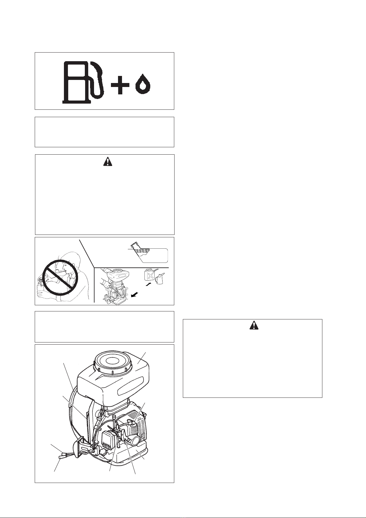
Throttle control
lever
Shutter control lever Carburettor Starter handle
Fuel tank
Spark plug
Straps
Cushion
back-plate
Chemical tank
Shoulder level
Fuel tank
3 m