Echo SRM-225 User manual

X7732278503
© 01/22 ECHO Incorporated
Operator’s Manual
SRM-225
Straight Shaft Trimmer
Burn Hazard
The muffler or catalytic muffler and surrounding cover may become
extremely hot. Always keep clear of exhaust and muffler area, otherwise
serious personal injury may occur.
The engine exhaust from this product contains chemicals known to the State of California to
cause cancer, birth defects or other reproductive harm.
Read and understand all provided literature before use. Failure to do so could result
in serious injury.

2X7732278503
© 01/22 ECHO Incorporated
TABLE OF CONTENTS SRM-225
TABLE OF CONTENTS
Introduction ........................................................................................................................................ 3
Additional or Replacement Manuals ............................................................................................ 3
Servicing Information ......................................................................................................................... 3
Parts and Serial Number.............................................................................................................. 3
Warranty Registration .................................................................................................................. 3
Service......................................................................................................................................... 3
Safety................................................................................................................................................. 4
Manual Safety Symbols and Important Information..................................................................... 4
International Symbols .................................................................................................................. 5
Personal Condition and Safety Equipment .................................................................................. 5
Equipment.................................................................................................................................... 8
Description....................................................................................................................................... 10
Contents .......................................................................................................................................... 11
Assembly ......................................................................................................................................... 12
Shield Installation....................................................................................................................... 12
Nylon Line Head Installation ...................................................................................................... 12
To Advance Trimmer Line.......................................................................................................... 13
Remove Nylon Line Head.......................................................................................................... 13
Support Handle Installation........................................................................................................ 13
Operation ......................................................................................................................................... 14
Fuel............................................................................................................................................ 14
Starting Cold Engine.................................................................................................................. 16
Starting Warm Engine................................................................................................................ 17
Stopping Engine......................................................................................................................... 18
Applications................................................................................................................................ 18
Operating Techniques - Nylon Line Head.................................................................................. 18
Operating Techniques - Metal or Plastic Blade.......................................................................... 19
Reaction Forces......................................................................................................................... 20
Blade Cutting Problems ............................................................................................................. 21
Maintenance .................................................................................................................................... 22
Skill Levels................................................................................................................................. 22
Maintenance Intervals................................................................................................................ 22
Air Filter...................................................................................................................................... 23
Fuel Filter................................................................................................................................... 23
Spark Plug ................................................................................................................................. 24
Cooling System.......................................................................................................................... 24
Exhaust System......................................................................................................................... 26
Carburetor Adjustment............................................................................................................... 27
Lubrication ................................................................................................................................. 28
Nylon Line Head Disassembly Instructions................................................................................ 29
Nylon Line Replacement............................................................................................................ 30
Troubleshooting ............................................................................................................................... 32
Storage ............................................................................................................................................ 33
Long Term Storage (Over 30 Days)........................................................................................... 33
Specifications................................................................................................................................... 34
Specifications................................................................................................................................... 35

SRM-225 INTRODUCTION
© 01/22 ECHO Incorporated
X7732278503 3
INTRODUCTION
Specifications, descriptions and illustrative material in this literature are as accurate as known at the time of
publication, but are subject to change without notice. Illustrations may include optional equipment and
accessories, and may not include all standard equipment.
Read and understand all provided literature. Literature contains specifications and information for
safety, operation, maintenance, storage and assembly specific to this product.
Additional or Replacement Manuals
Replacement Operator, Safety Manuals, and Parts Catalogs are available from your ECHO dealer or at
echo-latinamerica.com.
SERVICING INFORMATION
Parts and Serial Number
Genuine ECHO Parts and Assemblies for your products are
available only from an Authorized ECHO Dealer. When you do
need to buy parts always have the Model Number and Serial
Number of the unit with you. You can find these numbers on the
engine housing. For future reference, write them in the space
provided below.
Model No._____________________________
Serial No._____________________________
Warranty Registration
Your bill of sale must be provided to demonstrate proof of
warranty.
Service
Service of this product during the warranty period must be performed by an Authorized ECHO Service
Dealer. For the name and address of the Authorized ECHO Service Dealer nearest you, visit
echo-latinamerica.com.

4X7732278503
© 01/22 ECHO Incorporated
SAFETY SRM-225
SAFETY
Manual Safety Symbols and Important Information
Throughout this manual and on the product itself, you will find safety alerts and helpful, informational
messages preceded by symbols or key words. The following is an explanation of those symbols and key
words and what they mean to you.
The safety alert symbol accompanied by the word “DANGER” calls attention to an act or condition
which WILL lead to serious personal injury or death if not avoided.
The safety alert symbol accompanied by the word “WARNING” calls attention to an act or condition
which CAN lead to serious personal injury or death if not avoided.
The safety alert symbol accompanied by the word “CAUTION” calls attention to an act or condition
which may lead to minor or moderate personal injury if not avoided.
The enclosed message provides information necessary for the protection of the unit.
Note: This enclosed message provides tips for use, care and maintenance of the unit.
CIRCLE AND SLASH SYMBOL
This symbol means the specific action shown is prohibited. Ignoring these prohibitions can result in
serious or fatal injury.

SRM-225 SAFETY
© 01/22 ECHO Incorporated
X7732278503 5
International Symbols
Personal Condition and Safety Equipment
Cancer and Reproductive Harmwww.P65Warnings.ca.gov
Users of this product risk injury to themselves and others if the unit is used improperly and/or safety
precautions are not followed. Proper clothing and safety gear must be worn when operating unit.
Physical Condition
Your judgment and physical dexterity may not be good:
• If you are tired or sick.
• If you are taking medication.
• If you have taken alcohol or drugs.
Operate unit only if you are physically and mentally well.
Symbol
Description
Symbol Description Symbol Description Symbol Description
Warning,
See
Operator’s
Manual
Carburetor
Adjustment -
High Speed
Mixture
DO NOT
Allow Flames
or Sparks
Near Fuel
Ignition
ON / OFF
Wear Eye,
Ear and
Head
Protection
Carburetor
Adjustment -
Idle Speed
DO NOT
Smoke Near
Fuel
Purge Bulb
Wear Hand
and Foot
Protection
Carburetor
Adjustment -
Low Speed
Mixture
Choke
Control “RUN”
Position
(Choke Open)
Choke
Control
“COLD
START”
Position
(Choke
Closed)
Safety/Alert Stop Switch
Keep Feet
AwayFrom
Blade
Rotating
Cutting
Attachment
Hot Surface Fuel and Oil
Mixture
Thrown
Objects
Direction of
Blade
A V O I D K I C K O U T .
Keep Bystanders At Least
15 m (50 feet) Away
Keep Bystanders and
Helpers Away 15 m (50 ft.)
Bew a re T hrown O b je cts
Wear Eye Protection
Ignition
OFF
ON
STOP

6X7732278503
© 01/22 ECHO Incorporated
SAFETY SRM-225
Eye Protection
◆Eye protection that meets ANSI Z87.1 or CE requirements must be worn whenever you operate
the unit.
◆For additional safety, a full-face shield may be worn over safety glasses or goggles to provide
protection from sharp branches or flying debris.
Hand Protection
Wear sturdy, no-slip, rubber work gloves to improve your grip on the handles. Gloves also provide protection
against cuts and scratches, cold environments, and reduce the transmission of machine vibration to your
hands.
Hearing/Ear Protection
ECHO recommends wearing hearing protection whenever unit is used.
Breathing Protection
Operators who are sensitive to dust or other common airborne allergens may need to wear a dust mask to
prevent inhaling these materials while operating unit. Dust masks can provide protection against dust, plant
debris, and other plant matter such as pollen. Make sure the mask does not impair your vision, and replace
the mask as needed to prevent air restrictions.
Proper Clothing
Wear snug-fitting, durable clothing:
• Pants should have long legs, shirts should have long sleeves.
• DO NOT WEAR SHORTS.
• DO NOT WEAR TIES, SCARVES, JEWELRY, or clothing with loose or hanging items that could become
entangled in moving parts or surrounding growth.
• Keep clothing buttoned or zipped, and keep shirt tails tucked in.
Wear sturdy work shoes with nonskid rubber soles:
• DO NOT WEAR OPEN TOED SHOES.
• DO NOT OPERATE UNIT BAREFOOTED.
Keep long hair away from engine and air intake. Retain hair with cap or net.
Heavy protective clothing can increase operator fatigue, which may lead to heat stroke. Schedule heavy
work for early morning or late afternoon hours when temperatures are cooler.
The components of this machine generate an electromagnetic field during operation, which may
interfere with some pacemakers.To reduce the risk of serious or fatal injury, persons with
pacemakers should consult with their physician and the pacemaker manufacturer before operating
this machine.In the absence of such information, ECHO does not recommend the use of this
machine by anyone who has a pacemaker.

SRM-225 SAFETY
© 01/22 ECHO Incorporated
X7732278503 7
Extended Operation and Extreme Conditions
Prolonged exposure to cold and/or vibration may result in injury. Read and follow all safety and
operation instructions to minimize risk of injury. Failure to follow instructions may result in painful
wrist/hand/arm injuries.
It is believed that a condition called Raynaud’s Phenomenon, which affects the fingers of certain individuals,
may be brought about by exposure to vibration and cold. Exposure to vibration and cold may cause tingling
and burning sensations, followed by loss of color and numbness in the fingers. The following precautions
are strongly recommended, because the minimum exposure, which might trigger the ailment, is unknown.
• Keep your body warm, especially the head, neck, feet, ankles, hands, and wrists.
• Maintain good blood circulation by performing vigorous arm exercises during frequent work breaks, and
also by not smoking.
• Limit the hours of operation. Try to fill each day with jobs where operating the unit or other hand-held
power equipment is not required.
• If you experience discomfort, redness, and swelling of the fingers followed by whitening and loss of feeling,
consult your physician before further exposing yourself to cold and vibration.
Repetitive Stress Injuries (RSI)
It is believed that overusing the muscles and tendons of the fingers,
hands, arms, and shoulders may cause soreness, swelling,
numbness, weakness, and extreme pain in those areas. Certain
repetitive hand activities may put you at a high risk for developing a
Repetitive Stress Injury (RSI). An extreme RSI condition is Carpal
Tunnel Syndrome (CTS), which could occur when your wrist swells
and squeezes a vital nerve that runs through the area. Some believe
that prolonged exposure to vibration may contribute to CTS. CTS can
cause severe pain for months or even years.
To reduce the risk of RSI/CTS, do the following:
• Avoid using your wrist in a bent, extended, or twisted position.
Instead try to maintain a straight wrist position. Also, when
grasping, use your whole hand, not just the thumb and index finger.
• Take periodic breaks to minimize repetition and rest your hands.
• Reduce the speed and force with which you do the repetitive movement.
• Do exercise to strengthen the hand and arm muscles.
• Immediately stop using all power equipment and consult a doctor if you feel tingling, numbness, or pain in
the fingers, hands, wrists, or arms. The sooner RSI/CTS is diagnosed, the more likely permanent nerve
and muscle damage can be prevented.
All over head electrical conductors and communications wires can have electricity flow with high
voltages. This unit is not insulated against electrical current. Never touch wires directly or indirectly,
otherwise serious injury or death may result.

8X7732278503
© 01/22 ECHO Incorporated
SAFETY SRM-225
Do not operate this product indoors or in inadequately ventilated areas. Engine exhaust contains
poisonous emissions and can cause serious injury or death.
Read the Manuals
• Provide all users of this equipment with the Operator’s Manual and Safety Manual for instructions on Safe
Operation.
Clear the Work Area
• Spectators and fellow workers must be warned, and children and animals prevented from coming nearer
than 15 m (50 ft.) while the unit is in use.
Keep a Firm Grip
• Always hold throttle handle and support handle with thumbs and fingers tightly encircling the handles.
Keep a Solid Stance
• Maintain footing and balance at all times. Do not stand on slippery, uneven or unstable surfaces. Do not
work in odd positions or on ladders. Do not over reach.
Avoid Hot Surfaces
• Keep exhaust area clear of flammable debris. Avoid contact during and
immediately after operation.
Equipment
Use only ECHO attachments. Serious injury may result from the use of a non-approved attachment
combination. ECHO, Incorporated will not be responsible for the failure of cutting devices,
attachments or accessories which have not been tested and approved by ECHO. Read and comply
with all safety instructions listed in this manual and safety manual.
• Check unit for loose/missing nuts, bolts, and screws. Tighten and/or replace as needed.
• Inspect shield for damage and ensure that the cut-off knife is securely in place. Replace if either is
damaged or missing.
• Check that the cutting attachment is firmly attached and in safe operating condition.
• Check that handle and harness (if included) are adjusted for safe, comfortable operation. See Assembly
Section for proper adjustment.
Moving parts can amputate fingers or cause severe injuries. Keep hands, clothing and loose objects
away from all openings.
•ALWAYS stop engine, disconnect spark plug, and make sure all moving parts have come to a complete
stop before removing obstructions, clearing debris, or servicing unit.
•DO NOT start or operate unit unless all guards and protective covers are properly assembled to unit.

SRM-225 SAFETY
© 01/22 ECHO Incorporated
X7732278503 9
◆NEVER reach into any opening while the engine is running. Moving parts may not be visible through
openings.
Periodically Check fuel system (fuel lines, vent, grommet, fuel tank, and fuel cap) for leaks especially
if the unit is dropped. If damage or leaks are found, do not use unit, otherwise serious personal
injury or property damage may occur. Have unit repaired by an authorized servicing dealer before
using.

10 X7732278503
© 01/22 ECHO Incorporated
DESCRIPTION SRM-225
DESCRIPTION
Locate the safety decal(s) on your unit. Make sure the decal(s) is legible and that you understand and follow
the instructions on it. If a decal cannot be read, a new one can be ordered from your ECHO dealer.
X505-002500
4.5m (15ft)
PELIGRO DANGER
ESP
DANGER
FR
Tholam ipsum dolor sit amet,
consectetuer adipiscing elit, sed
diam nonummy nibh euismod
tincidunt ut laoreet dolore magna
aliquam erat volutpat Rautem vel
eum iriure dolor in hendrerit velit
esse amet feugiat in vulputate
velit. Ut wisi enim ad minim
veniam, quis nostrud exerci tation
ullamcorper suscipit lobortis nisl
ut aliquip ex adipis. Duis autem
vel eum iriure dolor in hendrerit in
vulputate velit esse amet feugiat
Tholam ipsum dolor sit amet,
consectetuer adipiscing elit, sed
diam quis nostrud exerci tation
ullamcorper suscipit lobortis nisl
Tholam ipsum dolor sit amet,
consectetuer adipiscing elit, sed
diam nonummy nibh euismod
tincidunt ut laoreet dolore magna
aliquam erat volutpat Rautem vel
eum iriure dolor in hendrerit velit
esse amet feugiat in vulputate velit.
Ut wisi enim ad minim veniam, quis
nostrud exerci tation ullamcorper
suscipit lobortis nisl ut aliquip ex
adipis. Duis autem vel eum iriure
dolor in hendrerit in vulputate velit
esse amet feugiat Tholam ipsum
dolor sit amet, consectetuer
adipiscing elit, sed diam quis
nostrud exerci tation ullamcorper
suscipit lobortis nisl sed diam
Tholam ipsum dolor sit amet,
consectetuer adipiscing elit, sed
diam nonummy nibh euismod
tincidunt ut laoreet dolore magna
aliquam erat volutpat Rautem vel
Oum iriure dolor in hendrerit velit
esse amet feugiat in vulputate velit.
Ut wisi enim ad minim veniam, quis
nostrud exerci tation ullamcorper
Muscipit lobortis nisl ut aliquip ex
adipis. Duis autem vel eum iriure
dolor in hendrerit in vulputate velit
esse amet feugiat Tholam ipsum
dolor sit amet, consectetuer
Adipiscing elit, sed diam quis
nostrud exerci tation ullamcorper
suscipit lobortis nisl sed diam
Bholam ipsum dolor sit amet,
consectetuer adipiscing elit, sed diam
nonummy nibh euismod tincidunt ut
laoreet dolore magna aliquam erat
volutpat Rautem vel eum iriure dolor in
Dendrerit velit esse amet feugiat in
vulputate velit. Ut wisi enim ad minim
veniam, quis nostrud exerci tation
ullamcorper suscipit lobortis nisl ut
aliquip ex adipis. Duis autem vel eum
iriure dolor in hendrerit in vulputate
velit esse amet feugiat Tholam ipsum
dolor sit amet, consectetuer adipiscing
elit, sed diam quis nostrud exerci
tation ullamcorper suscipit lobortis
nisl sed diam nonummy nibh euismod
tincidunt ut laoreenonum autem vel
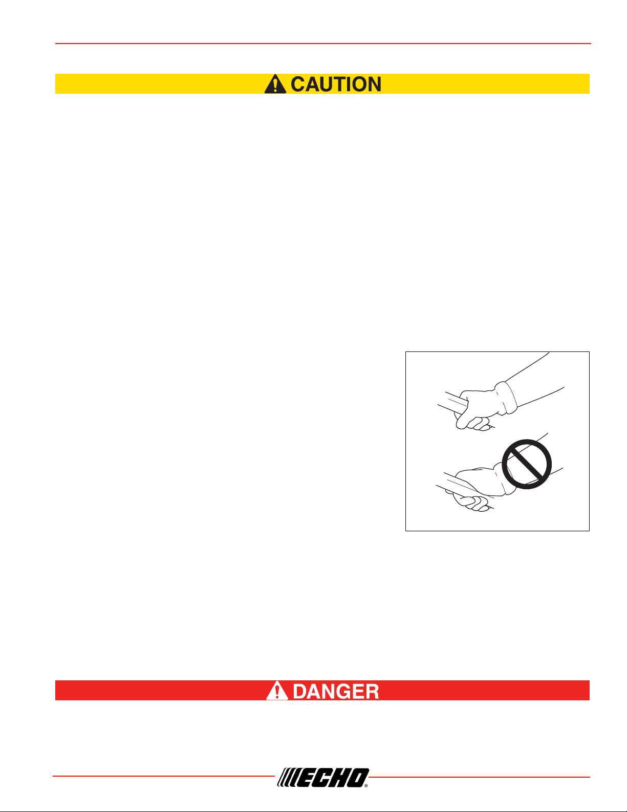
GT (CURVED SHAFT) UNITS
DO NOT INSTALL METAL BLADES ON
GT (CURVED SHAFT) MODEL
SRM (STRAIGHT SHAFT) UNITS
Oconsectetuer adipiscing elit, sed
diam nonummy nibh euismod
tincidunt ut laoreet dolore magna
aliquam erat volutpat Rautem vel eum
Biure dolor in hendrerit velit esse amet
feugiat in vulputate velit. Ut wisi enim
ad minim veniam, quis nostrud exerci
tation ullamcorper suscipit lobortis
nisl ut aliquip ex adipis. Duis autem
Iel eum iriure dolor in hendrerit in
vulputate velit esse amet feugiat
Tholam ipsum dolor sit amet,
12
3
4
5
6
7
89
10
11
12
14
13
15
16
17
18
19

SRM-225 CONTENTS
© 01/22 ECHO Incorporated
X7732278503 11
CONTENTS
The ECHO product you purchased has been factory pre-assembled for your convenience. Due to packaging
restrictions, some assembly may be necessary.
After opening the carton, check for damage. Immediately notify your retailer or ECHO Dealer of damaged or
missing parts. Use the contents list to check for missing parts.
_____ 1 - Power Head / Drive Shaft Assembly
_____ 1 - Operator’s Manual
_____ 1 - Nylon Trimmer Head
_____ 1 - Plastic Shield
_____ 1 - Shield Plate
_____ 3 - 5 x 16 mm Screws (shield mount)
1. Spark Plug
2. Top Guard
3. Recoil Starter Handle
4. Spark Arrestor Muffler or Spark Arrestor Muffler with Catalyst
5. Fuel Tank Cap
6. Fuel Tank
7. Air Cleaner
8. Choke Lever
9. Purge Bulb
10. Power Head
11. Throttle Handle - For Right Hand
12. Throttle Trigger Lockout
13. Throttle Trigger
14. Stop Switch
15. Support Handle - For Left Hand
16. Drive Shaft Assembly
17. Debris Shield with Cut-Off Knife
18. Cut-Off Knife
19. Nylon Cutter Head

12 X7732278503
© 01/22 ECHO Incorporated
ASSEMBLY SRM-225
ASSEMBLY
Shield Installation
(Nylon line operation)
Parts required: Debris Shield, Shield Plate, three 5 x 16 mm screws.
This unit cannot be converted for brushcutter use.
1. Place shield (A) on the bottom of the bearing housing
flange.
2. Place shield plate (B) on shield, align holes. Install three
screws from bottom through plate and shield into gear case.
3. Assemble adapter plate (C) onto PTO shaft.
Nylon Line Head Installation
Parts required: Nylon Line Head.
Wear Gloves or personal injury may result:
•Cutoff knife is sharp.
•Gearcase and surrounding area may be hot.
1. Be sure adapter plate (A) remains on PTO shaft (B).
2. Align locking hole in upper plate with notch in edge of gear
housing and insert head locking tool (C).
A
B
C
A
B
C

SRM-225 ASSEMBLY
© 01/22 ECHO Incorporated
X7732278503 13
3. Thread line head (D) onto shaft by turning it
counterclockwise until head is tight against the adapter
plate.
4. Remove locking tool (E).
Note: Your nylon line head may appear different than nylon line
head shown.
To Advance Trimmer Line
See Maintenance Section for nylon line replacement.
Note: To advance trimmer line, tap trimmer head against the
ground while the head is turning at normal operating
speed.
Remove Nylon Line Head
Note: Do not disassemble nylon line head.
1. Align locking hole in upper plate with notch in edge of gear
housing and insert head locking tool (A).
2. Remove line head (B) by turning it clockwise until head is
completely off of shaft.
3. Remove locking tool (A).
Support Handle Installation
Note: Label shows minimum spacing for support handle
location.
1. If necessary, position support handle for comfortable
operation and securely tighten screws.
E
D
A
B

14 X7732278503
© 01/22 ECHO Incorporated
OPERATION SRM-225
OPERATION
Moving parts can amputate fingers or cause severe injuries. Keep hands, clothing and loose objects
away from all openings. Always stop engine, disconnect spark plug, and make sure all moving parts
have come to a complete stop before removing obstructions, clearing debris, or servicing unit.
Engine exhaust IS HOT, and contains Carbon Monoxide (CO), a poison gas. Breathing CO can cause
unconsciousness, serious injury, or death. Exhaust can cause serious burns. ALWAYS position unit
so that exhaust is directed away from your face and body.
Operation of this equipment may create sparks that can start fires around dry vegetation.This unit is
equipped with a spark arrestor to prevent discharge of hot particles from the engine. Metal cutters
can also create sparks if the cutter strikes rocks, metal, or other hard objects. Contact local fire
authorities for laws or regulations regarding fire prevention requirements.
Fuel
Use of unmixed, improperly mixed, or fuel older than 90 days, (stale fuel), may cause hard starting, poor
performance, or severe engine damage and void the product warranty. Read and follow instructions in the
Storage section of this manual.
Fuel containing more than 25% ethanol is NOT approved for use in ECHO 2-stroke gasoline engines.
Fuel containing more than 25% ethanol may cause performance problems, loss of power,
overheating, fuel vapor lock, and unintended machine operation, including, but not limited to,
improper clutch engagement. Fuel containing more than 25% ethanol may also cause premature
deterioration of fuel lines, gaskets, carburetors and other engine components.
Fuel Requirements
Gasoline - Use 89 Octane (mid grade or higher) gasoline known to be good quality. Gasoline may contain
up to 25% Ethanol. Gasoline containing methanol (wood alcohol) is NOT approved.
Two Stroke Oil - A two-stroke engine oil meeting ISO-L-EGD (ISO/CD 13738) and J.A.S.O. FD Standards
must be used. ECHO brand 2-Stroke Oil meets these standards. Engine problems due to inadequate
lubrication caused by failure to use an ISO-L-EGD (ISO/CD 13738) and J.A.S.O. FD certified oil will void the
two-stroke engine warranty.
ECHO branded 2-stroke oils may be mixed at 50:1 ratio for application in all ECHO engines sold in the past
regardless of ratio specified in those manuals.

SRM-225 OPERATION
© 01/22 ECHO Incorporated
X7732278503 15
Handling Fuel
Fuel is VERY flammable. Use extreme care when mixing, storing or handling, or serious personal
injury may result.
•Use an approved fuel container.
•DO NOT smoke near fuel.
•DO NOT allow flames or sparks near fuel.
•Fuel tanks/cans may be under pressure. Always loosen fuel caps slowly allowing pressure to
equalize.
•NEVER refuel a unit when the engine is HOT or RUNNING!
•DO NOT fill fuel tanks indoors. ALWAYS fill fuel tanks outdoors over bare ground.
•DO NOT overfill fuel tank. Wipe up spills immediately.
•Securely tighten fuel tank cap and close fuel container after refueling.
•Inspect for fuel leakage. If fuel leakage is found, do not start or operate unit until leakage is
repaired.
•Move at least 3 m (10 ft.) from refueling location before starting the engine.
Mixing Instructions
1. Fill an approved fuel container with half of the required
amount of gasoline.
2. Add the proper amount of 2-stroke oil to gasoline.
3. Close container and shake to mix oil with gasoline.
4. Add remaining gasoline, close fuel container, and remix.
Spilled fuel is a leading cause of hydrocarbon emissions. Some states may require the use of automatic fuel
shut-off containers to reduce fuel spillage.
After use
• DO NOT store a unit with fuel in its tank. Leaks can occur. Return unused fuel to an approved fuel storage
container.
Storage - Fuel storage laws vary by locality. Contact your local government for the laws affecting your area.
As a precaution, store fuel in an approved, airtight container. Store in a well-ventilated, unoccupied building,
away from sparks and flames.
Stored fuel ages. Do not mix more fuel than you expect to use in thirty (30) days, ninety (90) days when a
fuel stabilizer is added.
Stored two-stroke fuel may separate. ALWAYS shake fuel container thoroughly before each use.

16 X7732278503
© 01/22 ECHO Incorporated
OPERATION SRM-225
Starting Cold Engine
The attachment will operate immediately when the engine starts, and could result in possible
serious injury.Keep movable parts of the attachment away from objects that could become
entangled or thrown, and surfaces that could cause loss of control.
1. Stop Switch
Move stop switch button (A) forward, away from the STOP
position.
2. Choke
Move choke lever (B) to COLD START ( ) position.
3. Purge Bulb
Pump purge bulb (C) until fuel is visible and flows freely in the
clear fuel tank return line. Pump bulb an additional four or five
times.
4. Recoil Starter
Lay the unit on a flat area and keep movable attachment parts
clear of all obstacles. Firmly grasp throttle handle and throttle
trigger lockout with left hand and fully depress throttle trigger
to wide open position. Rapidly pull recoil starter handle/rope
(D) until engine fires (or maximum five pulls).
A
C
B
D

SRM-225 OPERATION
© 01/22 ECHO Incorporated
X7732278503 17
5. Choke
After engine fires (or five pulls), move choke (B) to the RUN ( ) (open) position. Firmly grasp throttle
handle and throttle trigger lockout with left hand and fully depress throttle trigger to wide open position. Pull
starter handle/rope until engine starts and runs. Release throttle trigger and allow unit to warm up at idle for
several minutes.
Note: If engine does not start with choke in “RUN” position after five pulls, repeat instructions 2 - 5.
6. Throttle Trigger
After engine warm-up, grip throttle handle and support handle. Depress the throttle trigger lockout, and
gradually depress throttle trigger to increase engine RPM to operating speed.
Starting Warm Engine
The starting procedure is the same as Cold Start except DO NOT close the choke, and do not hold throttle
trigger fully depressed.
The attachment should not move at idle, otherwise serious personal injury may result.
Note: If attachment moves, readjust carburetor according to “Carburetor Adjustment” instructions in this
manual or see your ECHO Dealer.
1. Stop Switch
Move stop switch button (A) forward away from the STOP
position.
2. Purge Bulb
Pump purge bulb (C) until fuel is visible in the “Clear” fuel
return line. Pump bulb an additional four or five times.
A
C
B

18 X7732278503
© 01/22 ECHO Incorporated
OPERATION SRM-225
3. Recoil Starter
Lay the unit on a flat area and keep movable attachment parts
clear of all obstacles. Firmly grip throttle handle and throttle
trigger lockout with left hand. Rapidly pull recoil starter
handle/rope (D) until engine fires.
Note: If engine does not start after five pulls, use Cold Start
Procedure.
Stopping Engine
1. Throttle
Release throttle trigger and allow engine to return to idle before shutting off engine.
2. Stop Switch
Move stop switch button (A) backward to STOP position.
If engine does not stop when stop switch is moved to STOP position, close choke - COLD START
position - to stall engine. Have your ECHO dealer repair stop switch before using unit again.
Applications
Do not install blades on GT (Curved Shaft) trimmers.
Operating Techniques - Nylon Line Head
Nylon line heads may be used for trimming, scything, edging, and scalping of grass and light weeds.
Trimming
Feed the spinning line into the material to be cut. Tilt the line head to one side to direct cutting debris away
from you:
• Model SRM/DSRM/PAS/DPAS/SB/TX/C/T (Straight shaft, counter-clockwise line head rotation) - Tilt the
cutting head down on the right side while cutting to direct cutting debris away from operator. Feed the line
gradually into the material you wish to cut, avoiding contact with fences or other barriers.
• GT models: Tilt cutting head to the left while cutting to direct debris away from the operator.
D
A

SRM-225 OPERATION
© 01/22 ECHO Incorporated
X7732278503 19
Scything
Scything - Swing the cutting head in a level arc, gradually feeding the line into the material being cut. Move
forward with each arc to cut a swath. Width of cutting swath depends on arc. Use a larger arc for a wider
swath, or a smaller arc for a narrow swath. Keep line head tilted to direct cutting debris forward or away from
you.
Edging and Scalping
Both of these are done with the nylon line cutting head tilted at a steep angle. Scalping is removing top
growth, leaving the earth bare. Edging is trimming the grass back where it has spread over a pavement or
driveway. During both edging and scalping, hold the unit at a steep angle in a position where the debris, and
any dislodged dirt and stone, will not come back towards you even if it ricochets off the hard surface.
General
• Debris flows in direction of line head rotation. Change line head position to assure debris flow is directed
away from operator.
• Keep cutting line away from wire fences to avoid entanglement.
• Operate trimmer only with cutting head below knee height.
Operating Techniques - Metal or Plastic Blade
Brushcutter blades may be used to cut and trim a wide variety of materials. Refer to the blade selection
section for determining the correct blade for the application.
Scything (3, 8, and 80 tooth weed/grass, and brush blades)
• To cut large sections of field grass and weeds swing the cutting head in a level arc, gradually feeding the
blade into the material being cut. Adjust throttle speed according to your work.
•Do not swing the main pipe with arms. Turn hips to swing the blade horizontally from right to
left, and cut weeds on the left side of the blade.
• Do not scythe back and forth as the grass may scatter and kickback may occur easily.
• Tilt blade left by 5 to 10 degrees so that cut grasses will push left, making progress easier.
• Move forward with each arc to cut a swath.
•Width of cutting swath depends on arc. Use a larger arc for a wider swath, or a smaller arc
for a narrow swath. Suggested cutting width is about 1.5 m (4.9 ft).
• When scything large brush up to 0.5" diameter from right to left, avoid cutting with
highlighted section.

20 X7732278503
© 01/22 ECHO Incorporated
OPERATION SRM-225
Reaction Forces
◆The cutting attachment will continue to rotate even after the throttle is released, maintain control
of the unit until it has come to a complete stop.
◆Blade thrust may occur when the spinning blade contacts an object that it does not immediately
cut. Following proper cutting techniques will prevent blade thrust.
◆Blade thrust can be violent enough to cause the unit and/or operator to be propelled in any
direction, and possibly lose control of the unit.
◆Blade thrust can occur without warning if the blade snags, stalls or binds.
◆Blade thrust is more likely to occur in areas where it is difficult to see the material being cut.
Push or Pull - Kickout
During normal use, operating a brushcutter with a circular metal blade can produce sudden strong reaction
forces that are difficult to control. Strong reaction forces can cause a loss of balance or loss of control of the
equipment, resulting in serious injury to operator and bystanders.
Understanding what causes these reactive forces may help you to avoid them, and can help you to maintain
control of the equipment if you experience a sudden reaction during cutting. Reactive forces occur when the
force being applied by the cutting teeth of a blade meet resistance, and some of the cutting force is directed
back toward the equipment. The greater the cutting force or the amount of resistance, the greater the
reactive force.
Push and Pull Forces
Push and pull forces are reactive forces that push the equipment directly toward the operator, or
that pull the equipment directly away from the operator. These forces are the result of cutting on
the sides of the blade. The direction of the force depends on the side of the blade being used,
and the direction of blade rotation at the point of contact. The reactive force is in the opposite
direction of blade rotation at the contact point, regardless of where the contact is being made.
These types of reactive forces are also called “Blade Thrust.”
As shown in the illustration, a blade turning counterclockwise will cause the equipment to pull
away from the operator if the point of cutting resistance is on the left side of the blade. If the
point of cutting resistance is on the right side of the blade, the equipment will push back
toward the operator. In both examples, the reactive force is in the opposite direction of blade
rotation at the contact point where resistance occurs.
Kickout
Kickout is also a reactive force caused by resistance to cutting, but the direction of blade
thrust is lateral (to the left or right of the blade), instead of forward or back toward the
operator. In most cases, Push, Pull, and Kickout can be reduced or eliminated by:
• Using the correct blade for the cutting job
• Using properly sharpened blades
Other manuals for SRM-225
5
Table of contents
Other Echo Trimmer manuals

Echo
Echo GTE 350 User manual

Echo
Echo SRM-2320T User manual

Echo
Echo SRM-265TES User manual

Echo
Echo SRM-2400 TYPE 1E - 09-99 User manual

Echo
Echo SRM - 2400SB User manual

Echo
Echo HCAS-236ES-LW User manual

Echo
Echo DSRM-2600 User manual

Echo
Echo SRM - 2100SB User manual

Echo
Echo SRM-266U User manual

Echo
Echo HCA-2620 User manual