SERVICE INFORMATION
GT-220ES
SRM-220ES
8
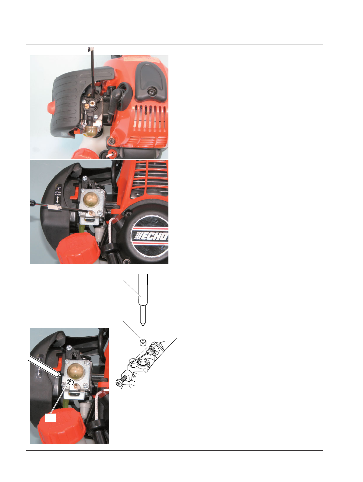
2-3 Adjusting carburettor
1. Start and warm up engine alternating engine
speed between WOT for 10 seconds and idle for 5
seconds for 3 minute.
NOTE : If the engine can’t start, turn Idle mixture
needle clockwise in 1/4 turn increments until the
engine starts.
2. Adjust Idle mixture needle to reach maximum
idle speed with 2.5 mm blade screwdriver.
3. Set idle speed to 3,800 r/min by turning Idle ad-
just screw. Engine speed should be stable at 3,800
+/- 50 r/min.
4. Turn Idle mixture needle anticlockwise to re-
duce engine idle speed 800 r/min to set idle speed
at 3,000 r/min. The idle speed range is 2,900 - 3,100
r/min.
NOTE : Engine speed must be allowed to stabilize
a minimum of 20 seconds after each adjustment of
idle mixture needle to assure accurate tachometer
readings.
5. Adjust Hi speed mixture needle to reach maxi-
mum WOT engine speed.(maximum approximate
7,300 r/min on GT-220ES, 8,800 r/min on SRM-
220ES with nylon line head, 10,500 r/min on SRM-
220ES with metal blade.) Then turn Hi speed
mixture needle anticlockwise to reduce WOT en-
gine speed 20 r/min.
6. Start engine again and verify engine idle speed
ranges from 2,600 to 3,400 r/min, and WOT en-
gine speed ranges from 7,000 r/min to 8000 r/min
on GT-220ES, 8,000 r/min to 9,700 r/min on SRM-
220ES with nylon line head, 9,500 r/min to 11,500
r/min on SRM-220ES with metal blade. Make sure
the cutter does not rotate when engine is idling.
When final adjustment is completed, the engine
should idle, accelerate smoothly, and attain WOT
per above specifications.
7. After adjusting carburettor, completely insert and
secure new plug (s) (J) P005-001270 deep in the
needle holes per the Emission directive using lim-
iter plug tool (H).
NOTE : Engine WOT, and idle engine speed in
field operation may vary from final adjustment
specifications due to changing ambient conditions,
fuel, and engine loads. Safe engine speed vari-
ances should be within the WOT and Idle speed
ranges listed in Section 1-1, otherwise the carbure-
tor should be readjusted.
(J)
(H)
(J)