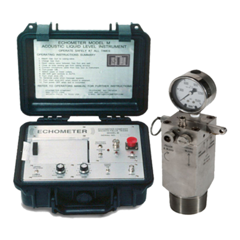
Echometer Model-H User manual

Echometer Company Model – H Manual Phone: (940) 767-4334
5001 Ditto Lane Page 1 Fa : (940) 723-7507
Wichita Falls, Te as 76302, U.S.A. E-Mail: info@echometer.com
Echometer Model-H
The Acoustic Liquid Level Instrument for Hazardous Environments
Introduction
This operating manual contains information about the Echometer Model H Fluid Level Instrument including
installation instructions, operating procedures, requirements for intrinsically safe application, maintenance,
shooting problem wells, record interpretation and technical references relating to the optimization of producing
wells. Please read the manual and view the e ample screens before operating the instrument. Additional
technical papers can be accessed from the Echometer Web page, www.echometer.com; these articles offer
additional information on the use of acoustic fluid level instruments to optimize production. Please read these
papers at your convenience.
Limits of Liability
Echometer Company reserves the right to revise its software and publications with no obligation of Echometer
Company to notify any person or any organization of such revision. In no event shall Echometer Company be
liable for any loss of profit or any commercial damage, including but not limited to special, consequential, or other
damages.
Information in this document is subject to change without notice and does not represent a commitment on the
part of Echometer Company. The software described in this document is furnished under a license agreement
or nondisclosure agreement. It may be used or copied only in accordance with the terms of the agreement. It is
against the law to copy the software or any medium e cept specifically allowed in the license or non-disclosure
agreement.
Copyright Notice
Copyright 2009, 2010 Echometer Company. All rights reserved. Federal copyright law protects this manual. No
part of this manual may be copied or distributed, transmitted, transcribed, stored in a retrieval system or
translated into any human or computer language, in any form or by any means, electronic, mechanical,
magnetic, manual, photographic, photocopy, scanning, or otherwise, or disclosed to third parties without the
e press written permission of Echometer Company.
Trademarks
AWP, TWM, QRod, Compact Gas Gun are trademarks of Echometer Company

Echometer Company Model – H Manual Phone: (940) 767-4334
5001 Ditto Lane Page 2 Fa : (940) 723-7507
Wichita Falls, Te as 76302, U.S.A. E-Mail: info@echometer.com
Table of Contents Echometer Model H Manual
Introduction ...................................................................................................................................................................... 1
Limits of Liability ......................................................................................................................................................... 1
Copyright Notice .......................................................................................................................................................... 1
Safety Considerations ....................................................................................................................................................... 4
Operation in Hazardous nvironments ......................................................................................................................... 4
Instructions X57H ..................................................................................................................................................... 5
chometer Schools ....................................................................................................................................................... 6
Instrument Description – Model H ................................................................................................................................... 7
Instrument Panel ........................................................................................................................................................... 8
General Operation Procedures ........................................................................................................................................ 11
Operation of the Model H with the Compact Gas Gun ................................................................................................... 11
Compression ( xplosion) Mode ................................................................................................................................. 11
Rarefaction (Implosion) Mode ................................................................................................................................... 12
Acquisition of Acoustic Records .................................................................................................................................... 13
Quick Reference…………………………………………………………………………………………………….13
Title Screen .............................................................................................................................................................. 14
Conditions of Operation ............................................................................................................................................. 15
Main Menu ................................................................................................................................................................. 16
Set-Up Menu .............................................................................................................................................................. 17
Well and Group Selection .................................................................................................................................... 19
Acoustic Record Acquisition ................................................................................................................................ 19
Prepare Well and Gas Gun for xplosion Shot ........................................................................................................ 20
Prepare Well and Gas Gun for Implosion Shot ........................................................................................................ 21
Background Noise Display ....................................................................................................................................... 21
Waiting for Shot to be fired ..................................................................................................................................... 22
Acquiring Data Screen ............................................................................................................................................. 23
Automatic Fluid Level Analysis........................................................................................................................... 24
Manual Adjustments ................................................................................................................................................ 24
Data Set Disposition ............................................................................................................................................. 25
Repeat Acquisition ................................................................................................................................................ 25
Set-Up Menu .................................................................................................................................................................. 27
Date and Time: ......................................................................................................................................................... 27
Sleep Minutes before Power Off .............................................................................................................................. 27
Operating Mode ....................................................................................................................................................... 28
Named Well .................................................................................................................................................... 28
Quick Shot: ..................................................................................................................................................... 28
Default Joint Length (ft) 31.7 ................................................................................................................................... 28
Default Acoustic Velocity (ft/sec) ............................................................................................................................ 28
nabled Shot ............................................................................................................................................................ 28
Initial Analysis Mode ............................................................................................................................................... 28
Screen Brightness: .................................................................................................................................................... 28
Units ......................................................................................................................................................................... 29
Recalling, Analyzing and Uploading Acoustic Records ................................................................................................. 30
Recalling and Analyzing Acoustic Records ................................................................................................................ 30
Analysis Options: ..................................................................................................................................................... 322
Automatic Collar and Liquid Level Analysis ......................................................................................................... 333
Toggle Filters: .............................................................................................................................................. 355
Adjust Collars: .............................................................................................................................................. 355
Adjust Liquid Level: ........................................................................................................................................ 39
Set Liquid Level Time Using Marker ...................................................................................................................... 39
Anomaly Marker Method ....................................................................................................................................... 400
General Description of Procedure ................................................................................................................ 400
dit Anomaly Menu...................................................................................................................................... 411
xample of Data Processing by the Anomaly Markers Method ............................................................................. 433

Echometer Company Model – H Manual Phone: (940) 767-4334
5001 Ditto Lane Page 3 Fa : (940) 723-7507
Wichita Falls, Te as 76302, U.S.A. E-Mail: info@echometer.com
Adjust Anomaly Marker Depths ................................................................................................................... 477
Anomaly Method – Adjust Liquid Level ...................................................................................................... 511
Acoustic Velocity Variation in Wellbore ..................................................................................................... 533
Acoustic Velocity Input ........................................................................................................................................... 53
Managing Well Data and Information .......................................................................................................................... 566
ntering New Group of Wells .................................................................................................................................. 566
Group Name Manual ntry..................................................................................................................................... 57
Well Name Manual ntry ........................................................................................................................................... 59
Well Information .................................................................................................................................................... 61
Wellhead Attachments .................................................................................................................................................... 62
Compact Gas Gun ....................................................................................................................................................... 62
Description of Compact Gas Gun Control Functions ................................................................................................. 62
Volume Chamber Pressure Gauge ............................................................................................................................ 63
Casing ( or Tubing) Pressure Gauge Quick Connector ............................................................................................ 63
Cocking Arm ............................................................................................................................................................ 63
Casing (or Tubing) Pressure Bleed Valve ................................................................................................................ 63
Gun Filler-Bleed Valve ............................................................................................................................................ 63
Trigger Pawl ............................................................................................................................................................. 63
Microphone .............................................................................................................................................................. 63
High Pressure Gas Guns ............................................................................................................................................. 64
Principles of Acoustic Measurements ............................................................................................................................. 65
Recording and Interpretation of Signals ..................................................................................................................... 65
Depth Calculation ....................................................................................................................................................... 66
Recommendations for Optimum Performance ............................................................................................................ 67
Acoustic Record Interpretation .................................................................................................................................. 68
Calculation of Bottomhole Pressures .......................................................................................................................... 68
Fluid Level Acquisition in Problem Wells ................................................................................................................ 69
Battery Power Information ......................................................................................................................................... 70
Important Notes and Instructions for Rechargeable Batteries .................................................................................... 70
Steps to Reset Model H Battery to Begin Taking a Charge………………………………………………………….71
Steps to Reset anc Charge a "Critically Low" Battery……………………………………………………………….72
Instument Testing/Troubleshooting ............................................................................................................................ 71
Maintenance ............................................................................................................................................................... 74
Compact Gas Gun Pressure Rating .......................................................................................................................... 74
Compact Gas Gun Disassembly and Assembly Special Precautions ........................................................................ 75
APPENDIX ............................................................................................................................................ 76
Microphone/Cable Test .............................................................................................................................................. 77
Rate of Fill-up Graph .................................................................................................................................................. 78
Use of Rate of Fill-up Information ............................................................................................................................. 79
CARBON DIOXID CYLIND R ............................................................................................................................. 80
CO2 Cylinder Schematic With Part Numbers ......................................................................................................... 81
CARBON DIOXID GAS INFORMATION (CO
2
) ............................................................................................... 82
CO2 - PHYSICAL CONSTANTS ........................................................................................................................... 82
NITROG N GAS INFORMATION (N
2
) .................................................................................................................. 83
ACOUSTIC LIQUID L V L D PTH M ASUR M NT CONSID RATIONS ................................................. 83
HANDLING PR CAUTIONS ................................................................................................................................ 83
N2 - PHYSICAL CONSTANTS .............................................................................................................................. 83
SUB-MANUAL
Model H Laptop Manager Soft are Quick Reference Guide

Echometer Company Model – H Manual Phone: (940) 767-4334
5001 Ditto Lane Page 4 Fa : (940) 723-7507
Wichita Falls, Te as 76302, U.S.A. E-Mail: info@echometer.com
Safety Considerations
Read this manual before operating the equipment.
Please observe all safety rules in operating this equipment. The pressure ratings of the Echometer gas
gun and all fittings, hoses, etc. should always e ceed actual well pressure. Because the wellhead pressure
normally increases during a build-up test, caution should be e ercised that the well pressure does not e ceed
equipment pressure ratings.
Do not use worn or corroded parts. A used or corroded fitting may not withstand original pressure rating.
All safety precautions cannot be given herein. Please refer to all applicable safety manuals, bulletins,
etc. relating to pressure, metal characteristics, temperature effects, corrosion, wear, electrical properties, gas
properties, etc. before operating this equipment.
The tests should not be undertaken if the operator, the test equipment and the well are not in conditions
to operate safely. This equipment should not be used if the operator is tired, ill or under the influence of alcohol,
drugs or medication.
The user must read, understand and accept the conditions for using the Echometer Model H in a
hazardous environment. Please refer to the section in this manual that describes the requirements to use the
instrument in a safe manner in or near a hazardous area where e plosive mi tures of gases may be present.
Operation in Hazardous Environments
The Echometer Model H is approved for operation in hazardous environments that are classified as Class I
Division 1 Groups C & D T4 and
,when installed and used in accordance with the instructions X57H, found on the following
page.
Note: To maintain Intrinsically Safe certification, the unit must be charged in a safe area and can only be
charged using Echometer P/N MS1610.
As part of the instrument set-up procedure and to be able to use the instrument, the user is e pected to read,
understand and ACCEPT the following conditions of operation:
• The user agrees to follow the instructions related to using the Echometer Model H in a hazardous
environment with regard to connecting to the well, connecting to the acoustic hardware and operating the
instrument to acquire, recall and analyze data.
• The user agrees that connecting the Echometer Model H to the battery charger will occur only in a NON
hazardous area.
• The user agrees that downloading or uploading data or software via the USB port will be done only in a
NON hazardous area and only by connecting to a Battery Powered laptop or notebook computer and
NEVER connecting the instrument to the USB port of a computer connected to an AC power source.
• The user understands that the Echometer Model H is not waterproof when the lid is opened and must be
kept dry while the case is opened.
• The user agrees that he is aware and understands that if any ONE of these requirements is not fulfilled
the Echometer Model H instrument will no longer meet the specifications of intrinsic safety.

Echometer Company Model – H Manual Phone: (940) 767-4334
5001 Ditto Lane Page 5 Fa : (940) 723-7507
Wichita Falls, Te as 76302, U.S.A. E-Mail: info@echometer.com
Instructions X57h

Echometer Company Model – H Manual Phone: (940) 767-4334
5001 Ditto Lane Page 6 Fa : (940) 723-7507
Wichita Falls, Te as 76302, U.S.A. E-Mail: info@echometer.com
Echometer Schools
Echometer Company offers schools on the use and applications of this equipment. You are invited to attend free
of charge. A list of the schools, which are taught throughout the United States and Canada, will be sent upon
request or can be viewed at http://www.echometer.com
Additional Information
Please contact Echometer Company to obtain additional information or to clarify any questions that you may
have in regard to the use of this instrument. The street and mailing address, phone number, fa number and e-
mail address are given on the first page.

Echometer Company Model – H Manual Phone: (940) 767-4334
5001 Ditto Lane Page 7 Fa : (940) 723-7507
Wichita Falls, Te as 76302, U.S.A. E-Mail: info@echometer.com
Instrument Description – Model H
The Echometer Model H is a stand alone, battery powered, microprocessor
controlled digital acoustic signal processor. When installed and used in accordance
with instructions X57H it is approved for operation in Class I Division 1 Groups C &
D and E II 1 G E ia IIB T4.
The Echometer Model H permits better interpretation of reflections from down hole
anomalies through application of digital filtering and processing that improve the
ability of the operator to distinguish down hole obstructions from enlargements. The
response from the liquid level (or a reduction in annulus area) is opposite to the
response from an enlargement such as a hole in the casing or perforations.
Selecting the proper digital filter will result in more accurate determination of the
number of tubing collar reflections from the surface to the liquid level.
A microprocessor is used with an analog to digital converter, memory chip,
amplifiers, clock, timing circuit and other electronic components to improve the
performance and utility of the instrument. When an acoustic pulse is generated in
the well, the signals reflected from the collars at the top of the well are large but
rapidly attenuate.
The microprocessor is used in conjunction with a real time clock. The timing
capabilities of the microprocessor, clock and timing circuit are used to determine the
round trip travel time with a resolution of +/- 0.001 seconds. In the automatic mode
of analysis, the travel time and the distance to the liquid level obtained by the
software by counting the collar echoes are used to compute the average acoustic
velocity of the gas in the annulus. The acoustic velocity, the casing pressure and average temperature can be
input to the utility program AWP 2000 (download at no cost from www.echometer.com) to compute the gas
gravity and the pressure distribution in the well, including the pump or tubing intake pressure and the pressure at
the perforations.
The entire instrument is contained in a waterproof, dustproof plastic housing having dimensions of 11 10 5
inches and weighs 11 pounds (5 kg). The following section describes the instrument panel and the function of
the various controls.

Echometer Company Model – H Manual Phone: (940) 767-4334
5001 Ditto Lane Page 8 Fa : (940) 723-7507
Wichita Falls, Te as 76302, U.S.A. E-Mail: info@echometer.com
Instrument Panel
The instrument panel is shown in the following Figure.
The panel incorporates both soft keys and a navigational 5-button star input keypad. A row of “soft key” buttons
below the LCD are used to e ecute the actions described in the labels at the bottom of the screen.
• Power Button:
Momentarily pressing the power button energizes the instrument fully and initiates the booting of the software.
The microprocessor performs a system test and displays the battery charge status. The instrument can be
turned off manually by pressing the power button.
• A 5-button Star Group:
The up, down, right, left, and enter are used to navigate through the menus and also to enter or edit program
parameters and well information.

Echometer Company Model – H Manual Phone: (940) 767-4334
5001 Ditto Lane Page 9 Fa : (940) 723-7507
Wichita Falls, Te as 76302, U.S.A. E-Mail: info@echometer.com
• Soft Keys
The function of each soft key change depending on the screen that is currently active. Their function is described
by the labels displayed at the bottom of the LCD display.
• Input Connector
This BNC INPUT connector is the input to the amplifiers. When acquiring data, this INPUT connector must be
connected to the microphone connector on the acoustic wellhead using a good coa ial cable with clean
connectors.
• USB Connector (left side)
This input/output connector is used to transfer well information records, acquired shot data records and analysis
results between the Model H and an e ternal computer running the Model H Laptop Manager Software.
• Battery Charger Connector (right side)
Connection to a battery charger should be made only when the instrument is outside the hazardous area.
Attaching the 110 VAC or the 220 VAC Echometer battery charger having an input of 110/220 VAC and an
output of 14.8 volts DC and 2Amps.
Note: To maintain Intrinsically Safe certification, the unit must be charged in a safe area and can only be
charged using Echometer P/N MS1610.

Echometer Company Model – H Manual Phone: (940) 767-4334
5001 Ditto Lane Page 10 Fa : (940) 723-7507
Wichita Falls, Te as 76302, U.S.A. E-Mail: info@echometer.com
• Battery Reset Button (Pin-Hole)
In the event of a necessary hard power down or battery reset, the pin-hole reset button can be accessed with a
paper clip. Depressing the pin-hole button will cut the power from the battery to the instrument causing a hard
reset of the battery. Pressing the power button will restore power to the unit and initiates booting of the software.
Caution should be used when utilizing the hard reset. It is recommended that the pin-hole reset button is
only pressed when the instrument is completely powered down.

Echometer Company Model – H Manual Phone: (940) 767-4334
5001 Ditto Lane Page 11 Fa : (940) 723-7507
Wichita Falls, Te as 76302, U.S.A. E-Mail: info@echometer.com
General Operation Procedures
Operation of the instrument is simple. First, the acoustic wellhead (gas gun) should be attached to the casing
annulus or tubing-head valve, and the cable should be connected between the microphone and the instrument.
The valve between the casing annulus and the flow line or between the tree wing valve and the flow line should
be closed to prevent the well gas from venting into the flow line causing e cessive noise. Then the instrument is
powered up and the user selects the mode of acquisition, prepares the gas gun for firing, generates the acoustic
pulse, stops data acquisition, reviews the data and saves the record to the instrument memory. When acquisition
of data at the well is complete, the microphone cable is disconnected from the gas gun, wellhead valves are
returned to their original position, pressure is relieved and the gas gun removed from the well. The following
sections illustrate in detail a mode of operation of the instrument and software.
Operation of the Model H with the Compact Gas Gun
The compact gas gun is operated either in the COMPRESSION (E plosion) mode or the RAREFACTION
(Implosion) mode. The operator should use the Compression (e plosion) technique when the casing pressure is
less than appro imately 100 psig. The Rarefaction (implosion) technique may be used whenever the casing
pressure is sufficient to obtain a good record.
Compression (E plosion) Mode
E pansion of gas from the Echometer gas gun is used to generate a pressure pulse. The pressure pulse is
positive since the gas chamber is charged to a pressure that e ceeds the well pressure by at least 100-psi.
• Securely attach the Echometer Gas Gun to the Casing or Tubing Valve.
• Close the Well Pressure Bleed Valve and Filler Bleed Chamber Valve.
• Lift the Cocking Arm to close the internal gas valve. This prevents debris from entering the volume
chamber.
• Open the Well Valve to the Echometer Gas Gun slowly and close the casing or wing valve to the flow
line.
• Measure the Well Pressure using the precision pressure gauge.
• Record Time and Well pressure.
• Fill the volume chamber with gas (CO2 or N2) to at least 100-psi (or more when a high background
noise level is present) in e cess of the Well Pressure.
• Connect the coa ial cable from the microphone to the Input of the Model H.
• Power up Instrument by pressing the left soft key.
• Navigate to the acquisition screen following the E plosion Pulse path as described in the following
section.
• Generate pressure pulse by pulling Trigger Ring, after the message “Waiting for Shot to be Fired” is
displayed.
• Inspect the record and repeat the shot if the signal quality is not satisfactory.
• Record Time and Well Pressure.
• Close the Valve between Echometer Gas Gun and the well.
• Open the Well Pressure Bleed Valve and release the pressure.
• Open the Casing Valve or Wing Valve to the flow line.
•
Remove the Echometer Gas Gun from the Casing or Tubing Valve.

Echometer Company Model – H Manual Phone: (940) 767-4334
5001 Ditto Lane Page 12 Fa : (940) 723-7507
Wichita Falls, Te as 76302, U.S.A. E-Mail: info@echometer.com
Rarefaction (Implosion) Mode
Gas is released from the well into the gas gun volume chamber to generate the initial pulse. Debris, moisture,
corrosive liquids and chemicals, and other foreign material may be imploded into the gas gun volume chamber,
which will increase maintenance requirements and may cause corrosion on the inside of the volume chamber.
• Securely attach the Echometer Gas Gun to the Casing or Tubing Valve.
• Close the Well Pressure Bleed Valve and Filler Bleed Chamber Valve.
• Open the Well Valve to the Echometer Gas Gun slowly and close the casing valve or the wing valve to
the flow line.
• Pull Trigger Ring.
• Lift the Cocking Arm to close the internal gas valve.
• Measure the Well Pressure using the precision pressure gauge.
• Record Time and Well Pressure.
• Bleed the gas chamber pressure through the Filler-Bleeder Chamber Valve by rotating the knob
clockwise until the gas gun pressure has decreased to appro imately 200-psi below the well pressure
reading. Use greater or less differential pressure depending on the background noise level.
• Connect the coa ial cable from the microphone to the INPUT of the Model H.
• Power up Instrument by pressing left soft key.
• Navigate to the Acoustic Record Acquisition screen following the Implosion Pulse path as described in
the following section.
• Generate pressure pulse by pulling Trigger Ring, after the message “Waiting for Shot to be Fired” is
displayed.
• Inspect the record and repeat the shot if the signal quality is not satisfactory.
• Record Time and Well Pressure.
• Close the Casing Valve or Tubing Valve between Echometer Gas Gun and the well.
• Open the Well Pressure Bleed Valve and release the pressure.
• Open the Casing Valve or Wing Valve to the flow line.
• Remove the Echometer Gas Gun from the Casing or Tubing valve.

Echometer Company Model – H Manual Phone: (940) 767-4334
5001 Ditto Lane Page 13 Fa : (940) 723-7507
Wichita Falls, Te as 76302, U.S.A. E-Mail: info@echometer.com
cquisition of coustic Records
– Model H Quick Reference
1 - Power up instrument by pressing the ON/OFF button on the instrument panel.
2 - Press the soft key corresponding to Continue” and select Accept” at the Conditions of
Operation.
3-To continue with Acquisition press the soft key below the Acquire Data label.
4- Use the Star Keys Up and Down buttons to select the group that contains the information
for the well being tested.
5- Use the Star Keys Right Arrow to select the Well option to display the list of wells included
in the chosen Group.
6- Use the Star Keys Up and Down arrows to select the desired well from the list.
7- Press the Acquire Shot” button on the instrument panel after the well has been selected
from the list (either pressing the button below the Select Well” label or the Enter” button of
the 5 button Star Keys)
8- Select the method of acquisition, Implosion” or Explosion,” and review the check list
displayed for connection and preparation of the hardware to perform the acoustic test.
9 – When ready press the button under the Continue” label and monitor the noise signal
strength to determine the level of differential pressure that should be used.
10 – Press the Start” button after adjusting the gas gun pressure if necessary.
11 – Actuate the gas gun control (trigger) to generate the pulse.
12 – Press the button under the Stop label to terminate acquisition after observing the liquid
level response and a repeat if desired.
13- Save or Discard the acquired shot.
14- Return to Main Menu or Retest the same well.

Echometer Company Model – H Manual Phone: (940) 767-4334
5001 Ditto Lane Page 14 Fa : (940) 723-7507
Wichita Falls, Te as 76302, U.S.A. E-Mail: info@echometer.com
cquisition of coustic Records
Following are illustrated the steps normally followed when acquiring fluid level acoustic record.
1 - Power up instrument by pressing the ON/OFF button on the instrument panel.
The following Self Test Screen is displayed for about 45 seconds:
The following Title screen is displayed after powering up the instrument:
Title Screen

Echometer Company Model – H Manual Phone: (940) 767-4334
5001 Ditto Lane Page 15 Fa : (940) 723-7507
Wichita Falls, Te as 76302, U.S.A. E-Mail: info@echometer.com
Check that the battery is adequately charged to successfully undertake the proposed testing sequence. The
color of the battery level indicator will turn from green to yellow when charging is required immediately. Regular
charging increases battery life.
2 - Press the soft key corresponding to Continue to display the following screen:
Selecting the Read Conditions options opens the following screens. Selecting the Accept option proceeds to
the Main Menu screen.
Conditions of Operation
If the user Declines to accept the conditions the program shuts FF the instrument. Page Down displays the
continuation of the te t detailing the conditions of operation.

Echometer Company Model – H Manual Phone: (940) 767-4334
5001 Ditto Lane Page 16 Fa : (940) 723-7507
Wichita Falls, Te as 76302, U.S.A. E-Mail: info@echometer.com
When the user Accepts the Conditions, the Main Menu is displayed as shown in the following figure:
Main Menu
The Main Menu Help Screen gives general instructions for user input and control as well as information
regarding the software version and instrument serial number:

Echometer Company Model – H Manual Phone: (940) 767-4334
5001 Ditto Lane Page 17 Fa : (940) 723-7507
Wichita Falls, Te as 76302, U.S.A. E-Mail: info@echometer.com
In the following description, the acquisition procedure assumes that the default mode of acquisition is the
“Named Well Mode” where the user first selects from the instrument’s data base the specific well information
where the acoustic test is being performed and then acquires the acoustic record. Upon completion, the data set
is added to the records for that specific well.
An alternate “Quick Shot” mode of acquisition can be preselected in the Setup menu as the default method
where the user is automatically directed to the acquisition screen without having to select a well from the data
base. The acquired record is then added to the previously acquired data sets in the “Quick Shot” group as a
record labeled with date and time of acquisition but no direct reference to the specific well that was tested. The
intent of the quick shot mode of acquisition is to obtain the fluid level data in a minimum of time for routine
monitoring of well operation.
Instrument Set-Up
The instrument is shipped with standard default options and quantities as displayed in the Set-Up Menu that is
accessed by pressing the button below the Setup label in the Main screen as discussed on page 25 of this
manual.
Any acquired data will be named according to the date and time the shot was taken. Make sure the date and
time are correct for your time zone so that your shot record will be accurate.

Echometer Company Model – H Manual Phone: (940) 767-4334
5001 Ditto Lane Page 18 Fa : (940) 723-7507
Wichita Falls, Te as 76302, U.S.A. E-Mail: info@echometer.com
3-To continue with Acquisition press the soft key below the Acquire Data label.
The following screen is displayed showing the available well groups with the name of the most recently selected
group highlighted. If the Selected Group column title is not displayed with a list of Groups displayed below it, use
the left arrow key to highlight the Selected Group column.
Well and Group Selection
4- Use the Star Keys Up and Down buttons to select the group that contains the
information for the well being tested.
In the above figure the “E amples” group has been selected. If the desired Group is not in the list pressing the
button under the “Add New Group” label will display the screen that allows adding new groups to the list as
described later in this manual.

Echometer Company Model – H Manual Phone: (940) 767-4334
5001 Ditto Lane Page 19 Fa : (940) 723-7507
Wichita Falls, Te as 76302, U.S.A. E-Mail: info@echometer.com
5- Use the Star Keys Right Arrow to select the Well option to display the list of wells included
in the Examples” group:
The selected well is highlighted: “Automatic Analysis Collars”
6-Use the Star Keys Up and Down arrows to select the desired well from the list.
If the well to be tested is not in the list pressing the button under the “Add New Well” label will display the
screens that allow adding new wells to the list as described later in this manual.
Acoustic Record Acquisition
7- Press the Acquire Shot” button on the instrument panel after the well in question has been
selected from the list (either pressing the button below the Select Well” label or the Enter”
button of the 5 button Star Keys)

Echometer Company Model – H Manual Phone: (940) 767-4334
5001 Ditto Lane Page 20 Fa : (940) 723-7507
Wichita Falls, Te as 76302, U.S.A. E-Mail: info@echometer.com
The Select Test screen is displayed so that the user may select the type of pulse: “Implosion” or E plosion”
8a-Pressing the button below Explosion” label displays the check list for connection and
preparation of the hardware to perform the acoustic test.
Prepare Well and Gas Gun for E plosion Shot
Table of contents
Other Echometer Measuring Instrument manuals
Popular Measuring Instrument manuals by other brands
Raytech
Raytech TR-Mark III 250V instruction manual
Gas Clip Technologies
Gas Clip Technologies Infrared user manual
OHAUS
OHAUS Ranger 3000 Series instruction manual
Burkert
Burkert 8746 operating instructions

PCB Piezotronics
PCB Piezotronics IMI SENSORS 628F11/-0005 Installation and operating manual
IKE
IKE 4 Setup guide

