Alemite 3644-C2 Technical specifications

2


6
B Notes
.................................................................................................................................................
.................................................................................................................................................
.................................................................................................................................................
.................................................................................................................................................
.................................................................................................................................................
.................................................................................................................................................
.................................................................................................................................................
.................................................................................................................................................
.................................................................................................................................................
C
Using the manual.
• The instructions provided by this manual satisfy both the Installer's and the Users'
requirements (Manager and Operators) of the METER.
In the Table of Contents a symbol alongside each paragraph indicates the person this
information is intended for.
All paragraphs marked with this symbol concern the Operator. The
operator is the person who uses the METER to carry out dispensing
operations. Therefore the Operator is not expected to read paragraphs
other than those marked with this symbol.
All paragraphs marked with this symbol concern the Manager. The
METER oers several options (selection of the Unit of Measurement,
selection of the Number of Decimal Digits, Calibration, etc.). At least
one skilled Operator (hereinafter referred to as the Manager) must
know this data in order to allow the Operators to use the METER
correctly. The Manager must read thoroughly all paragraphs
concerning the Manager and the Operator.
•
The following symbols are used to highlight important notes and information:
Warning
Warning
This symbol highlights important aspects as to the
CORRECT USE of the METER.
This symbol highlights important aspects as to SAFETY.
This symbol highlights important aspects as to avoid
POLLUTION HAZARDS.
Manager
Operator
Warning
All paragraphs marked with this symbol concern the Installer only. He
is responsible for installing the METER and is required to read the
manual thoroughly, no paragraph omitted.
Installer


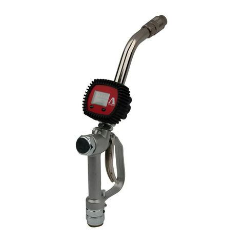
E. Alarge liquid-crystal display,
integrated in the 5-key keypad, for the
communication between the METER
and the Operator.
F. Amotorized valve shutting system,
automatically activated by a
microprocessor when dispensing a
PRESELECTED amount (AUTO mode).
G. Amulti-position extension to
adjust the angle of the dripless valve
with respect to the handle.
H.Adripless automatic valve.
8
D1
Detailed information on the METER
Swivel and lter
The METER is equipped with a swivel to
be connected to the exible hose.
The swivel is equipped with a 1/2"
female thread (BPS or NPT) and houses
the lter.
The large ltering surface guarantees a
reduced pressure loss.
Rubber swivel cover
During installation the swivel may be
equipped with a rubber cover to
prevent the swivel itself or the metal
end of the exible hose from damaging
the vehicle body.
This cover is available in dierent
colours, which can be used as a "colour
code" to identify the dispensed product
easily.
Handle An external shock-resistant plastic cover contains all the
components of the METER and provides an ergonomic handle.
The battery pack
The battery pack is placed in the front
part of the handle and it is xed by
means of four cross-head screws.
The user can easily access this pack to
replace the batteries.
Filter


10
Warning
During the operations necessary to
customize the METER, the keys
have extra functions, described in
paragraph G.
Numeric keys:
to be used to set the PRESET value
(automatic dispense stop value).
Keypad
The keypad is of membrane type
and is equipped with 5 keys.
AUTO key:
to be used to select and
conrm the PRESET value.
RESET key:
to be used to reset the Batch
Total and to display the
ResettableTOTAL.
.
Meter
To guarantee an accurate measurement
of the dispensed amount the METER
uses the principle of the oval gears.
Multi-position extension
To guarantee an easy use, the METER is
equipped with a multi-position
extension. It can be positioned by the
operator within a 75° range.
75°

In addition the automatic
dripples valve can be
rotated of 240°.
30°
30°
11
English
Français
Deutsch
Italiano
Español


15
E2 Line pressure relief
English
FrançaisDeutsch
Italiano
Español
Warning
Warning
This operation is to be carried out to
replace the pre-existing nozzle with the
METER nozzle or to dismount the
METER for maintenance purposes.
• Close the shut-o valve. Otherwise
stop the power supply pump and make
it unserviceable to avoid an accidental
re-start during maintenance operations.
• Operate the valve of the nozzle to be
replaced (or of the METER to be
disassembled for maintenance reasons)
dispensing into a suitable container in
order to release the line pressure.
• (For the dismounting of the METER
only) Remove the rubber cover from its
coupling on the swivel and move it
along the exible hose in order to have
easy access to the swivel.
• By means of two wrenches, unscrew
the threaded end of the exible hose
from the swivel.
Be careful to collect any oil leakage
into a suitable container.
If a dripless valve is installed at the
end of the nozzle, the pressure inside
the line will not decrease to zero, but
it may stay at a value of 0.2 - 0.5 bar
according to the type of dripless
valve used.
Failure to carry out this line pressure
relief procedure may cause damage
to persons or things.
Warning

16
E3 Flushing the lines
E4 Preliminary checks of the METER
Flushing the lines means to let a given
amount of oil ow through them so as
to ensure a proper "washing" of the
whole system, a correct cleaning and
the absence of dirt, contaminated
material or processed waste inside the
lines before installing the nozzle.
The ushing operation must be carried
out on all lines, upstream the nozzle. In
case the system is equipped with more
than one nozzle, ush the lines which
supply the nozzles farthest away from
the supply pump rst, then proceed
with the lines of the nozzles situated
nearer the pump.
This operation is absolutely
necessary with NEW INSTALLATIONS
or if the lines used are contaminated.
You need not carry out this
procedure when replacing the nozzle
in use.
The ushing procedure depends on the
type and features of the system and
must be carried out by trained and
qualied personnel in compliance with
the procedures set down by the
installer.
• Make sure that the threaded end tted
on the exible hose is suitable for the
swivel of the METER provided with:
• Check that the METER to be installed
is complete and in good condition,
making sure that the lter is clean and
correctly installed (see paragraph“H2”).
The lter of the METER, characterized by
a large ltering surface, has been
designed to guarantee a correct ltering
and a low pressure loss.
To remove and re-install the lter refer
to paragraph "H2".
The absence of the lter or its
improper installation may cause the
meter or the METER valve to block if
dirt is present in the tubes. This
situation may occur especially during
new installations.
To solve these problems consult a
qualied Service Centre.
Warning
Warning
Female thread 1/2" BSP
or
Female thread 1/2" NPT
Filter

17
E5 Mounting the extension on the METER
E6 Mounting the METER
Three dierent types of extensions can
be installed on the nozzle METER:
•ADJUSTABLE extension;
• RIGID extension;
• FLEXIBLE extension.
All of them are equipped with an
automatic dripless valve.
All extensions are equipped with a rigid
ending part (external ?12 mm, 3/8"G
nut) suitable for being easily connected
to the METER without using any sealant.
• Remove the plug from outletA(3/8”G).
•Make sure that gasket B on the
connector is in its seat.
•Lubricate the gasket and its seat.
•Tighten end D on METER by means of
two wrenches;
while the rst one on outletAblocks the
METER, the second one tightens nut C
of end D.
Before locking nut C orientate valve E.
An improper tightening of the
extension may cause it to become
loose thus endangering persons or
things.
Tighten the ring nut with a torque
wrench setting at 3.5 Kgm.
Warning
• Fit the rubber cover of the swivel into
the exible hose, in the direction
indicated in the gure, making it slide
over the male thread of the hose.
•Apply a thread sealant to the male
threads of the exible hose.
•Tighten the swivel completely by
means of two wrenches.
• Make the rubber cover slide towards
the valve until it goes into the specially
provided seat, located on the swivel.
Italiano
English
Français
Deutsch
Español
A
B
C
D
E


Other manuals for 3644-C2
1
Table of contents
Other Alemite Measuring Instrument manuals