EchoStar Hughes 9450 Series User manual

Hughes 9450 Series
User Guide
H64159
Revision A
27 December 2019

Copyright © 2011 - 2019 Hughes Network Systems, LLC
All rights reserved. This publication and its contents are proprietary to Hughes Network
Systems, LLC. No part of this publication may be reproduced in any form or by any means
without thewritten permission of Hughes Network Systems, LLC, 11717 Exploration Lane,
Germantown, Maryland 20876.
Hughes Network Systems, LLC has made every effort to ensure the correctness and
completeness of the material in this document. Hughes Network Systems, LLC shall not
be liable for errors contained herein. The information in this document is subject to change
without notice. Hughes Network Systems, LLC makes no warranty of any kind with regard
to this material, including, but not limited to, the implied warranties of merchantability and
fitness for a particular purpose.
Trademarks
Hughes and Hughes Network Systems are trademarks of Hughes Network Systems, LLC.
All other trademarks are the property of their respective owners.

•
Contents
H64159 Revision A
iii
Contents
Understanding safety alert messages.....................................................................................v
Messages concerning personal injury....................................................................................................v
Messages concerning property damage.................................................................................................v
Safety symbols.......................................................................................................................vi
Introduction............................................................................................................................1
Overview .............................................................................................................................................1
9450 Variants.......................................................................................................................................2
About this User Guide..........................................................................................................................3
Package Contents .................................................................................................................................3
Minimum System Requirements for Laptop/PC....................................................................................3
Getting Started .....................................................................................................................................4
Installing your terminal ........................................................................................................................4
Terminal LED functionality..................................................................................................................4
Using the Hughes 9450...........................................................................................................6
Auto start configuration........................................................................................................................6
Power up and the connection to the Internet..........................................................................................7
Connecting the terminal to the computer...............................................................................................7
Connecting by Ethernet.....................................................................................................................8
Power over Ethernet (POE)...............................................................................................................8
Connecting by WLAN......................................................................................................................8
WLAN Security............................................................................................................................9
Connecting by ISDN.........................................................................................................................9
Connecting by RJ11........................................................................................................................10
Coverage Map....................................................................................................................................11
Operation in the MEAS cutout area.................................................................................................12
Operation in the Russian Federation................................................................................................13
Using the Web UI.................................................................................................................14
Accessing the Web UI........................................................................................................................14
Home page.........................................................................................................................................16
Connections .......................................................................................................................................19
Manage Connections ......................................................................................................................19
Automatic Contexts........................................................................................................................20
Manage APNs ................................................................................................................................25
SMS...................................................................................................................................................27
Send/Receive..................................................................................................................................27
Saved Drafts...................................................................................................................................28

iv
•
Contents
H64159 Revision A
Sent Messages................................................................................................................................28
SMS Settings..................................................................................................................................29
Settings page......................................................................................................................................31
General Setup.................................................................................................................................31
IP Address/DHCP Settings .............................................................................................................33
Nat Mode....................................................................................................................................35
NAPT Mode...............................................................................................................................35
Relay Mode................................................................................................................................35
Port Forwarding Page.....................................................................................................................36
Wireless LAN.................................................................................................................................37
Wireless LAN Security...................................................................................................................40
Telephony ......................................................................................................................................42
Security..........................................................................................................................................44
Features..........................................................................................................................................46
M2M Page .........................................................................................................................................48
Ping Configuration:.....................................................................................................................48
Always On Context:....................................................................................................................48
Usage Page.........................................................................................................................................50
Support Page......................................................................................................................................51
Smart Phone Web UI..........................................................................................................................54
Troubleshooting ...................................................................................................................56
PDP Context Activation Errors.......................................................................................................56
Technology Overview...........................................................................................................59
GPS....................................................................................................................................................59
Obtaining a GPS Fix.......................................................................................................................59
GPS and BGAN Registration..........................................................................................................60
ISDN..................................................................................................................................................60
Dialing and Numbering...................................................................................................................60
PDP Context ......................................................................................................................................60
Technical Specifications.......................................................................................................62
Regulatory Notices...............................................................................................................63
EU Declaration of Conformity............................................................................................................63
FCC Compliance................................................................................................................................63
EU WEEE (Waste Electrical and Electronic Equipment) Directives....................................................63
Glossary................................................................................................................................64

•
Safety
H64159 Revision A
v
Understanding safety alert messages
Safety alert messages call attention to potential safety hazards
and tell you how to avoid them. These messages are identified
by the signal words DANGER, WARNING, CAUTION, or
NOTICE, as illustrated below. To avoid possible property
damage, personal injury, or in some cases possible death read
and comply with all safety alert messages.
Messages concerning
personal injury
The signal words DANGER, WARNING, and CAUTION
indicate hazards that could result in personal injury or in some
cases death, as explained below. Each of these signal words
indicates the severity of the potential hazard.
DANGER indicates a potentially hazardous situation which, if
not avoided, will result in death or serious injury
WARNING indicates a potentially hazardous situation which, if
not avoided, could result in death or serious injury.
CAUTION indicates a potentially hazardous situation which, if
not avoided, could result in minor or moderate injury.
Messages concerning
property damage
NOTICE is used for messages concerning possible property
damage, product damage or malfunction, data loss, or other
unwanted results—but not personal injury.

vi
•
Safety
H64159 Revision A
Safety symbols
The generic safety alert symbol calls attention to a
potential personal injury hazard. It appears next to the
DANGER, WARNING, and CAUTION signal words as part of
the signal word label. Other symbols may appear next to
DANGER, WARNING, or CAUTION to indicate a specific type
of hazard (for example, fire or electric shock). If other hazard
symbols are used in this document, they are identified in this
section.
Additional symbols
Warning Potential Radio Frequency (RF)
hazard. Where you see this alert symbol and
WARNING heading, strictly follow the
warning instructions to avoid injury to eyes or
other personal injury.
Warning Where you see this alert symbol and
WARNING heading, strictly follow the
warning instructions to avoid personal injury.
Danger Electric shock hazard: Where you see
this alert symbol and DANGER heading,
strictly follow the warning instructions to avoid
electric shock injury or death.
Warnings for Satellite Terminal
Do not stand in front of the Antenna This
device emits radio frequency energy. To avoid
injury, do not place head or other body parts in
front of the satellite antenna when system is
operational. Maintain a distance of one meter or
more from the front of the Satellite Terminal
antenna.
General Handle your Satellite Terminal with
care. The outdoor unit is weather resistant per
IEC 60529 IP56; however, do not submerge
either unit. Avoid exposing your Satellite
Terminal to extreme hot or cold temperatures
outside the range -25ºC to +55ºC.
Avoid placing the Terminal close to cigarettes,
open flames or any source of heat.
•
Safety
H64159 Revision A
vii
Changes or modifications to the Terminal not
expressly approved by Hughes Network
Systems could void your authority to operate
this equipment.
Only use a soft damp cloth to clean the
Terminal.
To avoid impaired Terminal performance,
please ensure the unit’s antenna is not damaged
or covered with foreign material like paint or
labeling.
When inserting the SIM, do not bend it or
damage the contacts in any way. When
connecting the interface cables, do not use
excessive force.
In the vicinity of blasting work and in
explosive environments Never use the Satellite
Terminal where blasting work is in progress.
Observe all restrictions and follow any
regulations or rules. Areas with a potentially
explosive environment are often, but not
always, clearly marked. Do not use the
Terminal while at a petrol filling station. Do not
use near fuel or chemicals.
Qualified Service Do not attempt to
disassemble your Satellite Terminal. The unit
does not contain consumer-serviceable
components. Only qualified service personnel
may install or repair equipment.
Accessories Use Hughes approved accessories
only. Use of non-approved accessories may
result in loss of performance, damage to the
Satellite Terminal, fire, electric shock or injury.
Connecting Devices Never connect
incompatible devices to the Satellite Terminal.
When connecting the Satellite Terminal to any
other device, read the device’s User Manual for
detailed safety instructions.

viii
•
Safety
H64159 Revision A
Pacemakers The various brands and models of
cardiac pacemakers available exhibit a wide range
of immunity levels to radio signals. Therefore,
people who wear a cardiac pacemaker and who
want to use a Satellite Terminal should seek the
advice of their cardiologist. If, as a pacemaker
user, you are still concerned about interaction with
the Satellite Terminal, we suggest you follow
these guidelines:
•Maintain a distance of 20cm from the Wi-
Fi antenna and your pacemaker:
•Maintain a distance of one meter from the
main antenna front and sides and your
pacemaker;
•Refer to your pacemaker product literature
for information on your particular device.
If you have any reason to suspect that interference
is taking place, turn off your Satellite Terminal
immediately.
Hearing Aids Most new models of hearing aids
are immune to radio frequency interference from
Satellite Terminals that are more than 2 meters
away. Many types of older hearing aids may be
susceptible to interference, making it very difficult
to use them near a Terminal. Should interference
be experienced, maintain additional separation
between you and the Satellite Terminal.
Electrical Storms Operation of the Satellite
Terminal during electrical storms may result in
severe personal injury or death. Ensure the Below
Deck Equipment is properly grounded to the
vehicle chassis.

•
Introduction
H64159 Revision A
1
Introduction
Overview
The Hughes Network Systems 9450 Broadband Satellite
Terminal is your gateway to global communication. The
9450 series terminal allows you to simultaneously send and
receive IP packet and circuit-switched data via Ethernet
(Power over Ethernet) ports and the Integrated Services
Digital Network (ISDN) interfaces over the Inmarsat BGAN
satellite network.
Depending on the version, this unit offers you the following
features and benefits:
•Fully autonomous tracking antenna acquires and tracks
the BGAN satellite signal while on the move
•Optional antenna installation (magnetic mount) on
vehicle roof
•Includes RF cable and power cable for vehicular
installation
•Up to 492 Kbps data (transmit and receive) and 256
Kbps streaming IP data rate (above 45 degrees look
angle) for C10 and 128Kbps streaming for C11
•Four RJ-45 Power over Ethernet (PoE) ports (except
9450L and 9450LW)
•Compressed voice calls (except 9450L and 9450LW)
•3.1KHz audio (above 20 degrees look angle to the
satellite for C10 and above 45 degrees for C11) (except
9450L and 9450LW)
•ISDN UDI/RDI data (64Kbps) (above 20 degrees look
angle to the satellite for C10 and above 45 degrees for
C11) (except 9450L, 9450LW and 9450TW)
•Multi-user capability for sharing a single unit
•Selectable Quality-of-Service (QoS)
•Full IP compatibility for Email, file transfer (FTP),
browsing, VPN, etc.
•Cost-effective “always-on” access – charges only for
data sent and received
•UMTS IP-based services
•FCC and CE certified
•Subscriber Identification Module (SIM) card security

2
•
Introduction
H64159 Revision A
With the optional mag mount installation method, the unit is
easy to install and connects in minutes. It is built for use in
vehicular environments.
In this document, the following names and abbreviations are
used to identify the Satellite Terminal and your computer.
Term
IDU
ODU
Definition
Indoor Unit
Outdoor Unit/antenna
Terminal
Satellite Terminal
TE
Terminal Equipment (your computer)
UT
User Terminal/satellite terminal
9450 Variants
There are multiple versions of the 9450 each with different
interfaces as listed in the table below. Depending on the
version, certain features will not apply.
The different models use different software release versions
as shown below. The upgrader protects against loading the
wrong release.
9450 Model
Part Numbers
Interfaces
Software Release
9450
Kit: 3500497-0001 C11
3500497-0002 C10
3500497-0010 C10
3500497-0013 C11
•Radio: 3500462-0001
•or 3500462-0005
4 port 100BaseT Ethernet switch with PoE
802.11b WLAN
ISDN
2 RJ11 ports
5.7.x.y
9450E
Kit: 3500497-0008 C11
3500497-0012 C10
•Radio: 3500462-0003
4 port 100BaseT Ethernet switch with PoE
ISDN
2 RJ11 ports
5.7.x.y
9450L
Kit: 3500497-0015 C11
3500497-0014 C10
•Radio: 3500462-0006
4 port 100BaseT Ethernet switch only
5.7.x.y or 6.7.x.y
9450LW
Kit: 3500497-0019 C11
3500497-0018 C10
•Radio: 3500462-0008
4 port 100BaseT Ethernet switch
802.11b/g/n WLAN
6.7.x.y
9450TW
Kit: 3500497-0021 C11
3500497-0020 C10
•Radio: 3500462-0011
4 port 100BaseT Ethernet switch with PoE
802.11b/g/n WLAN
2 RJ11 ports
6.7.x.y

•
Introduction
H64159 Revision A
3
About this User Guide
This user guide contains the most up-to-date information
available on this product, on the date it was generated. It is
focused on the specific information needed to operate the
Hughes 9450 Land Mobile User Terminal.
For information on using LaunchPad, please refer to the
Inmarsat website where a copy of the ‘Inmarsat LaunchPad
Guide’ can be downloaded:
http://www.inmarsat.com/Support/bgan-firmware/bgan-
launchpad/
LaunchPad is not supported when the 9450 is in M2M mode.
Package Contents
When you unpack the Land Mobile Terminal Kit package,
you will find the following:
•BGAN Land Mobile Tracking Antenna Kit
•Hughes 9450 BGAN Satellite Modem Kit
Your Service Provider will supply you with a Subscriber
Identification Module (SIM) and its PIN, and Satellite
Terminal configuration instructions –you will need these to
access the network. Note: The SIM card may also have
four (4) MSISDN numbers associated with it for various
ISDN services:
•4K Voice
•3.1KHz Audio/Fax
•64K UDI data
•56K RDI data
Minimum System
Requirements for
Laptop/PC
These are the minimum computer system requirements for
successful interface with the Satellite Terminal:
•Internet Browser: Chrome (9450 SW release 6.7.1.1 and
above), Internet Explorer, Edge, Firefox or Safari.

4
•
Introduction
H64159 Revision A
•PC Support for at least one of these interfaces: Ethernet,
or WLAN (802.11b or b/g).
•100 MB of free hard disk space (if using LaunchPad).
Getting Started
This guide is the simplest and quickest way to connect to
the BGAN network. If you are a first time user, you will
be guided through the procedure for powering up your
terminal, obtaining a GPS fix, connecting your computer
to the terminal and registering with the BGAN network.
You are then ready to start using voice and broadband
services.
Installing your
terminal
Install the Hughes 9450 terminal according to the
Installation Guide supplied with the terminal for either the
C10 or C11 antenna. You can also download the Installation
guides and User manuals from our website at
www.bgan.hughes.com . Please refer to the Installation
Guides for grounding instructions.
Terminal LED
functionality
The 9450 IDU has 4 LEDs with the following functions:
Power: Green when IDU is powered on. Off when IDU is
powered off. This LED is integrated in the On/Off switch.
Network Registration: Green when registered and attached
with Inmarsat BGAN network; Off otherwise.
GPS: Flashing Green while acquiring fix and solid Green
when valid GPS fix acquired. The GPS LED turns off when
the UT registers with the network and the network LED
turns on.
H/W Fault: Red if HW fault detected, e.g.: IB fault, no
communication to antenna or no GPS. Off otherwise.

•
Introduction
H64159 Revision A
5
The 9450 IDU has a four RJ-45 connector with 2 LEDs for
each port with the following functions:
Green/Red bicolor: Green indicates Link active; Red
indicates a power over Ethernet PD device is connected and
is being powered by the IDU. When both functions are
active, it will appear Orange in color.
Green: Traffic indicator

6
•
Using the Web UI
H64159 Revision A
Using the Hughes 9450
Auto start
configuration
Since the Hughes 9450 terminal is equipped with a
tracking antenna, the default configuration for the Hughes
9450 Land Mobile Terminal is as follows:
•The Hughes 9450 is configured to automatically register
with the network by default: The terminal will
automatically attempt to register with the network once
the tracking antenna has acquired the satellite signal and
obtained a GPS fix.
•The IDU has a power switch and an ignition sense line.
For the unit to turn on, the power switch must be in the
ON position and 12V or 24V applied to the ignition
sense line. Refer to the 9450 Installation Guide P/N
3004129-0001.

•
Using the Web UI
H64159 Revision A
7
Power up and the
connection to the
Internet
After power is applied, the Hughes 9450 IDU and Hughes
Tracking Antenna will begin their start-up sequence. The
tracking antenna will begin its search for the BGAN
satellite and the antenna motors may be heard during this
time. Note that the tracking antenna must have line of sight
to the BGAN satellite. Once the antenna has locked onto
the BGAN satellite, it will continue to make minor
adjustments to acquire optimum signal strength. The
antenna may be heard ‘twitching’ during this time.
Eventually the antenna will sit at an optimum position
while the vehicle is stationary.
Once the vehicle starts moving, the Hughes Tracking
Antenna will automatically track the satellite signal and
keep the antenna pointed towards the satellite. During
short outages (e.g. while driving under a bridge, etc.) the
antenna will remain in the same position and will pick up
the satellite signal immediately. For longer outages the
antenna may need to repeat the search pattern to reacquire
the satellite signal.
Circuit switched and packet switched connections will
typically recover from signal outages of less than 60
seconds. User intervention will be required to reactivate
circuit switched connections for outages longer than 60
seconds and may be required for packet switched
connections depending upon the actual length of outage.
Packet switched connections like FTP are more robust
than circuit switched connections in the network.
Connecting the
terminal to the
computer
You can connect your computer to the 9450 IDU with one
or more of the following interfaces
•Ethernet
•WLAN (not 9450E or 9450L)

8
•
Using the Web UI
H64159 Revision A
•During initial setup, the terminal can only be configured
using an Ethernet connection. Once the terminal has
been configured, all interfaces can be used for data
transfer.
Connecting by Ethernet
To connect the BGAN terminal to a device using Ethernet,
connect an Ethernet cable to your device’s Ethernet port,
and insert the other end of the connector into one of the
four Ethernet ports on the 9450 IDU. These four Ethernet
ports support Power-over-Ethernet (PoE) (except on the
9450L and LW).
Power over Ethernet (POE)
Note, PoE is not supported on the 9450L or LW.
All four PoE ports are powered by a single 48 Volt DC
power supply. The total power supplied by PoE is limited
to 30.8 W maximum for 12 V installations and 61.6 W
maximum for 24 V installations. The ports can provide
power to class 1, 2, and 3 devices as long as the total
power does not exceed the wattage based on the input
voltage provided. If a device is connected to a port that
exceeds the maximum power available, power will not be
provided to that port. The existing connections will not be
affected.
Connecting by WLAN
Note: WLAN is not available on the 9450E or 9450L.
If you have not previously used the IDU’s WLAN
interface, it has to be enabled from the internal web UI
with your computer connected to the IDU using the
Ethernet interface.
•WLAN Power: The default is off, which disables the
WLAN feature.
•SSID (network name): The default is BGAN, but you
can change it to whatever you want.
•Channel Number: This controls the radio channel
number (1 through 11) used by the access point. To meet
FCC regulations, channels 12 to 14 are not supported.

•
Using the Web UI
H64159 Revision A
9
When configuring the WLAN, you can enable the
Wireless security protocol and MAC address filtering for
added security.
Once the WLAN is “Enabled” and configured, any device
with a WLAN interface can detect the IDU’s WLAN SSID
and connect to it automatically.
The 9450LW and TW support up to 4 WLAN clients.
WLAN Security
For WLAN security, select from the following:
9450: No protection, 64 bit WEP, or 128 bit WEP
9450LW/TW: No protection, WPA, or WPA2
MAC Filtering: For added security, check the box to
“Enable” MAC Filtering. You can define up to 10 MAC
addresses that are allowed to connect to your WLAN.
When WLAN is enabled, unauthorized users may be able
to access your BGAN service. If WEP or WPA is enabled,
you must provide other WLAN users with the security key
in order for them to connect to the terminal. In NAT mode
you can go to the Manage Connections page to see what
computers are actually using the BGAN service.
Connecting by ISDN
Note: ISDN is not available on the 9450L, LW or TW.
Connect an ISDN cable to your computer’s or phone’s
ISDN port, and insert the other end of the connector into
the Terminal’s ISDN port.
To dial, prefix the international number with 00 and
terminate with #. For example, to dial a number in the
USA, enter: 0018005551234#
To receive incoming calls, you must configure your ISDN
device with the MSN (Multiple Subscriber Number) of the
service it supports. See the ISDN section for information
on configuration of MSNs. To configure the MSN in your
ISDN device, refer to the user guide of your ISDN device.

10
•
Using the Web UI
H64159 Revision A
Inmarsat only allow Class 11 terminals to use ISDN at
elevation angles of 45 degrees or greater and Class 10
terminals at elevation angles of 15 degrees and greater.
Check with your service provider for full details.
Connecting by RJ11
Note: RJ11 is not available on the 9450L or LW.
You can connect an analog phone or fax machine to the
RJ11 ports:
•The FAX port is configured for 3.1k service for fax
•The TEL port is configured for speech service for voice
calls
Inmarsat only allow Class 11 terminals to use Fax or
3.1kHz at elevation angles of 45 degrees or greater and
Class 10 terminals at elevation angles of 15 degrees and
greater. Check with your service provider for full details.
To dial, prefix the international number with 00 and
terminate with #. For example, to dial a number in the
USA, enter: 0018005551234# (00 + Country code + phone
number)
Operational note: RJ11 and ISDN handsets cannot be
connected at the same time. The 9450 will configure itself to
ISDN or RJ11 mode depending on which type of handset is
plugged in first and will be in this mode thereafter.
To switch modes, the 9450 must be rebooted with only the
desired handset connected. If both types of handsets are
connected at power-on, the 9450 will default to ISDN
mode and RJ11 will not be operational.
•
Using the Web UI
H64159 Revision A
11
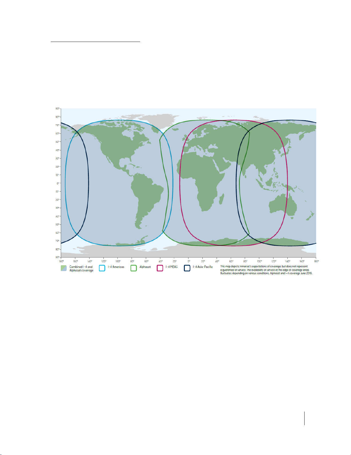
Coverage Map
The Inmarsat BGAN service is operated with 4 satellites as
shown below. The Hughes 9450 terminals will perform
best in areas where the elevation angle is 20 degrees or
higher. Lower elevation angles increase the probability of
signal outages caused by trees, buildings and hilly terrain
and may severely impact the usability on the move.

12
•
Using the Web UI
H64159 Revision A
Operation in the MEAS cutout area
I-4 MEAS has a cutout area in its coverage over China and
nearby parts of Asia. In this area, I-4 Asia Pacific (APAC)
must be used even if MEAS is closer. For best operation in
this area configure the UT to use only APAC from the
General Setup page (31).
This manual suits for next models
26
Table of contents
Other EchoStar Marine GPS System manuals


