Simrad CS66 Operating and maintenance instructions

SIMRAD CS66 4-ch
Chart System
20221867F sw.2.1 English
INSTALLATION MANUAL

Simrad CS66 4-channels Chart system
Document revisions
Rev Date Written by Checked by Approved by
A 110504
B 210405
C 301105
D 060106
E 070906
F 191107
Document history
Rev.
A First issue
B New back-up and restore procedure
C New software release (1.3.xx.) with minor changes in System
Configuration dialog. Cabling diagram updated.
D CD ROM replaced with DVD in MC50 computer, new backup
recovery procedure.
E New software release (2.1.xx.) implementing the IMO S-52
requirements (C-MAP SDK 3.6). Minor changes to MMI.
F New speaker, affecting illustrations, cable length and dim.
drawing
ii 20221867 / F

INSTALLATION MANUAL
Content
1INTRODUCTION ................................................................1
1.1 General.............................................................................1
1.2 Unpacking and handling ......................................................1
1.3 System components............................................................2
2INSTALLATION..................................................................3
2.1 Location of the units ...........................................................3
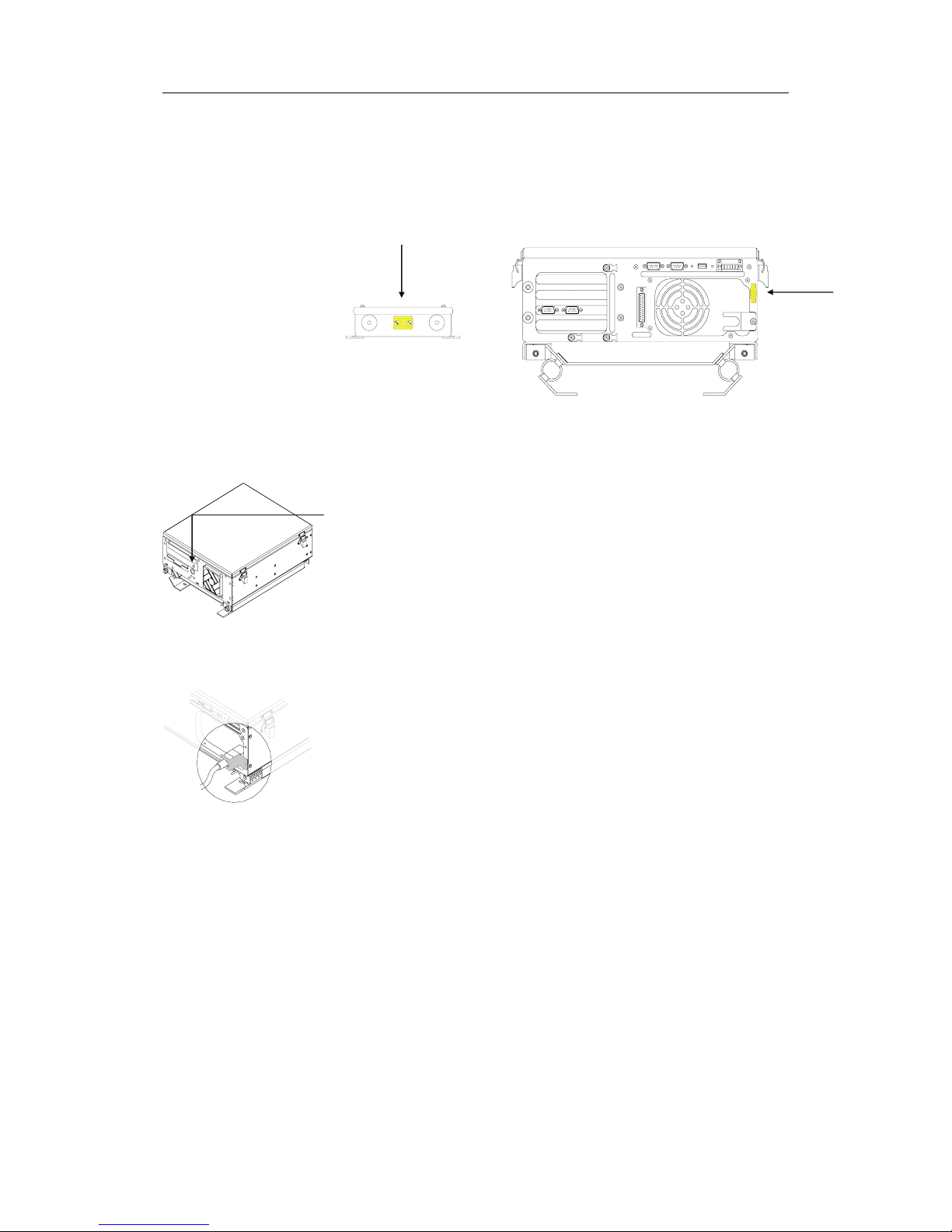
2.2 Mechanical installation ........................................................3
MC50 Computer ............................................................3
FB200 MC24 Filterbox (24V systems only) ........................4
Speaker .......................................................................4
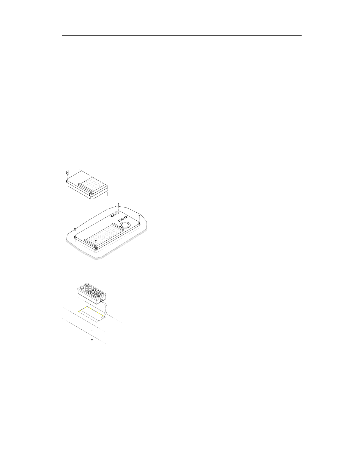
Keyboard and TrackMan®wheel ......................................4
COP20 Operator panel (Option) .......................................5
COP10 Remote Operator panel (Option) ...........................5
Monitor........................................................................5
2.3 Grounding the units ............................................................6
2.4 Power connection ...............................................................6
115/230V AC ................................................................6
24V DC ........................................................................7
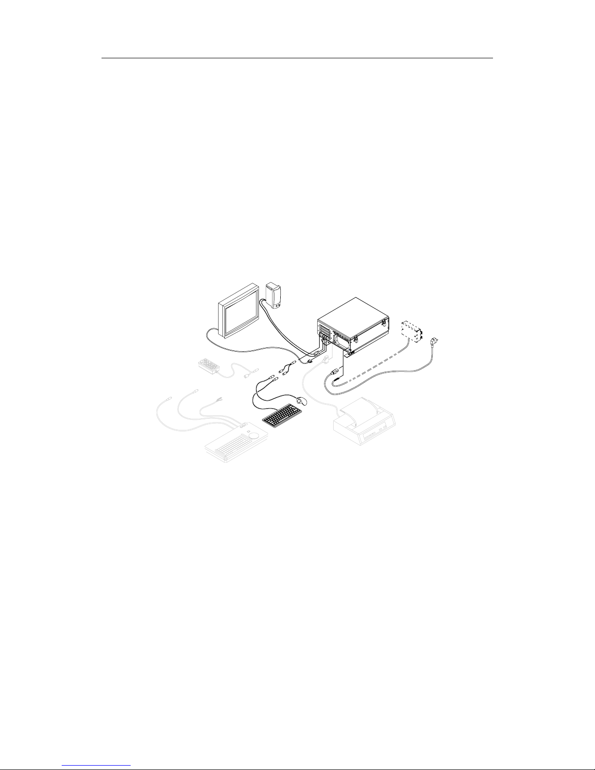
2.5 Cable connections...............................................................8
Cable layout .................................................................8
Connecting external equipment ..................................... 10
Connecting optional operator panels .............................. 11
3SYSTEM CONFIGURATION ...............................................13
3.1 The System configuration dialog ......................................... 13
3.2 Input configuration ........................................................... 14
Adding new device ...................................................... 15
Advanced input settings ............................................... 17
Modifying an input device ............................................. 17
Deleting an input device............................................... 18
Monitoring a serial line ................................................. 18
3.3 Output configuration ......................................................... 19
3.4 Checksum ....................................................................... 20
3.5 Auxiliary settings.............................................................. 21
3.6 Miscellaneous settings ....................................................... 22
20221867 / F iii

Simrad CS66 4-channels Chart system
3.7 Ship settings.................................................................... 24
4BACKUP AND RESTORE PROCEDURES .............................25
4.1 General........................................................................... 25
4.2 Making a back-up ............................................................. 25
4.3 Restoring the software ...................................................... 26
4.4 Re-installing/updating the CS software ................................ 27
5TECHNICAL SPECIFICATIONS .........................................29
5.1 Cabling ........................................................................... 29
5.2 MC50 computer unit.......................................................... 30
5.3 Cherry keyboard............................................................... 30
5.4 Speaker .......................................................................... 31
5.5 FB200 Filterbox (only for 24V DC systems) .......................... 31
COP20 Operator panel (Option) ................................................... 32
5.6 COP10 Remote Operator panel (Option)............................... 32
5.7 IP protection .................................................................... 33
6DRAWINGS .....................................................................35
6.1 MC50 Marine Computer ..................................................... 36
Front view.................................................................. 36
Side view ................................................................... 37
Bottom view ............................................................... 38
6.2 Cherry keyboard............................................................... 39
6.3 Mounting bracket for speaker ............................................. 40
6.4 FB200 Filter box (Option) .................................................. 41
6.5 COP10 (Option)................................................................ 42
6.6 COP20 (OPTION) .............................................................. 43
6.7 Cabling diagram ............................................................... 44
6.8 COP10, Panel cut-out ........................................................ 45
6.9 COP20, Panel cut-out ........................................................ 47
iv 20221867 / F

INTRODUCTION
20221867 / F 1
1INTRODUCTION
1.1 General
This manual provides detailed information required to
successfully install and configure the CS66 system.
The manual must be used in conjunction with the instructions
and drawings designed for the specific vessel, and should
remain with the vessel on completion of the installation to serve
as an additional reference during maintenance of the system.
1.2 Unpacking and handling
Care should be taken when unpacking and handling the
equipment. A visual inspection should be made to see that the
equipment has not been damaged during shipment and that all
components and parts are present.

Simrad CS66 4-channels Chart system
1.3 System components
A standard CS66 system includes the following units:
-MC50 Marine computer
-FB200 MC24 Filterbox (for 24V systems only)
-Cherry keyboard
-Logitech TrackMan®wheel
-Splitter cable for TrackMan wheel and keyboard
-Speaker
-Color monitor (may be supplied by others)
The basic system may be expanded with a COP20 Operator
panel, a COP10 remote operator panel, and with a printer.
2 20221867 / F

INSTALLATION
20221867 / F 3
Note!
2INSTALLATION
2.1 Location of the units
The units included in the CS66 system should be mounted with
special regard to the units’ environmental protection,
temperature range and cable length.
The CS66 units are designed to operate within the temperature
range of 0°C to +55°C. However, it is recommended that
adequate ventilation/air-conditioning is provided in order to
keep the ambient operating temperature at +20°C.
It is also recommended that the area around the units is kept
relatively free from dust and build-up static electricity.
2.2 Mechanical installation
Installing devices are not included with the units.
MC50 Computer
The MC50 has to be mounted horizontally, and should not be
installed close to heavy transformers or similar.
Other equipment should not be stored upon the MC50 unit.
For 24V systems, the unit should be mounted as close as
possible to the FB200 Filter box as the cable length between
FB200 and MC50 is limited to 0.8 m.
The mounting location should allow access to the power button,
the CD/DVD and the floppy drive. It is also necessary to have
working area when replacing the air inlet fans’ dust filter.
Refer dimensional drawing showing recommended working
area, page 36 onwards.

Simrad CS66 4-channels Chart system
Use the following procedure when mounting the unit:
1Loosen the 2 screws on the front of
the unit, slide the computer cabinet
1-2 cm aside, and lift the cabinet
upwards to release it from the
mounting plate
2Prepare 8 holes in the deck where
the mounting plate is to be located.
Refer dimensional drawing, page
38.
3Secure the mounting plate to the
deck with 8 bolts.
4Reinstall the computer cabinet to
the mounting plate.
FB200 MC24 Filterbox (24V systems only)
The FB200 filter box has to be mounted as close as possible to
the MC50, as the cable length between FB200 and MC50 is
limited to 0.8 m.
The FB200 is preferred to be mounted vertically, and should not
be installed close to heavy transformers or similar.
FB200 is secured to the bulkhead with four screws. Refer
dimensional drawing on page 41.
Speaker
The speaker is supplied with a mounting bracket. Use 2 screws
to secure the speaker to the panel.
Refer dimensional drawing, page 40.
Keyboard and TrackMan®wheel
No installation devices are included for these units.
4 20221867 / F

INSTALLATION
COP20 Operator panel (Option)
COP20 should be located where it is most convenient for the
user, with special regard to the user’s need for easy operation.
Refer standard and optional cable length for cables between
operating panels and MC50 unit, page 29.
It is recommended that adequate ventilation/air-conditioning is
provided in order to keep the ambient operating temperature at
+20°C.
Use the following procedure when installing the COP20:
1Cut a hole where COP20 is to be fitted. Refer
dimensional drawing on page 43, and the cut-out
template on page 47.
2Lift the four removable corners from the panel.
3Locate COP20 in the hole, and secure the unit to
the panel with four 4mm screws.
4Reposition the removable corners on the panel.
COP10 Remote Operator panel (Option)
COP10 is designed to be mounted in the helmsman chair’s
armrest.
1Cut the necessary holes in the armrest where COP10 is to
be fitted. Refer COP10 dimensional drawing on page 42,
and the cut-out template on page 45.
2Secure the unit to the panel with the nut as shown on the
figure.
Monitor
Refer to separate documentation delivered with the monitor for
installation procedures.
20221867 / F 5

Simrad CS66 4-channels Chart system
2.3 Grounding the units
MC50 and FB200 should have a proper ground connection from
the units’ ground terminal. The wires should be as short as
possible and have a cross section of at least 16mm2(gauge).
2.4 Power connection
MC50 has a power switch located on the front panel.
If the mounting location for the unit complicates access to this
switch, an external power switch should be used. This power
switch should be connected to TB1 as shown on page 9.
115/230V AC
To avoid that vibration should cause the plug to loose
connection, the fixing bracket should be used to secure the
power cable.
Loosen the bracket, and connect the power cable to the
115/230V connector on the MC50 back panel. The unit has auto
select function, and no manual switch has to be set for selecting
115 or 230V.
Secure the cable by fastening the fixing bracket again.
The system is delivered with standard European power
connector. If other power connector is to be used, replace the
European power connector with the selected connector on the
original power cable.
Note!
6 20221867 / F

INSTALLATION
24V DC
If the CS66 system is to be supplied with 24V DC, the power
should be connected via the FB200 Filter box.
Do not connect 24V without using this filter box. Doing so may
course electromagnetic interference!
1Remove the cover on the FB200, and connect the cable
from 24V DC supply according to the labelling on the
terminals as shown on the figure below.
This cable is not supplied with the equipment! It should have a
cross section of at least 2.5mm2(gauge).
Note!
GND
+
-
FROM
24V DC SUPPLY
TO
MC50 24V DC
POWER-IN
TERMINALS
2Connect the cable from FB200 to the 24V DC power-in
jack on the MC50.
3Secure the cable to the fixing bracket to avoid that
vibration should cause the plug to loose connection.
20221867 / F 7

Simrad CS66 4-channels Chart system
2.5 Cable connections
Refer to CS66 Cabling diagram, page 44.
Cable layout
The figure below shows the MC50 connector layout.
J1
COM3
COM4
PS2 port. Used for TrackMan Wheel and keyboard (connected
via splitter cable). Refer symbols on cable plug for correct
connection.
Firewire.
USB.
Ethernet.
The ethernet cable should be removed when not in use. If the
cable is connected, this may slow down the computer capacity.
Line out for Speaker.
Monitor.
J2
COM3 and COM4. NMEA channels used for connecting
external equipment.
8 20221867 / F

INSTALLATION
J3, J4
Not used.
COM 1, COM 2
NMEA channels used for connecting external equipment.
USB 2
USB.
TB 1
1
2 Pre-heat.
3
4 External ON/OFF switch.
5
6 Display illumination for the COP20 (OPTION).
Parallel
Printer port.
Power
24V DC or 115/230V AC power input.
20221867 / F 9

Simrad CS66 4-channels Chart system
Connecting external equipment
Four optical isolated NMEA converters are included in the CS66
system. These must be used for connecting external equipment
to COM1 – COM4 on the MC50.
Connect the 9-pins plug to the selected communication port on
MC50, and connect the cable to external equipment according to
the manufacturer’s specification and according to the table
below.
SIGNAL NAME COLOR
RX + Yellow
RX - Red
TX + Green
TX - Blue
COM 1-4
GND Braided screen
Caution The supplied NMEA converters include active components
inside the connector house. No external equipment must be
connected to the system without using these cables. The cables
can only be replaced with cables ordered from Simrad!
10 20221867 / F

INSTALLATION
Connecting optional operator panels
If a COP20 is to replace the Cherry keyboard and the TrackMan
Wheel, the keyboard and mouse cable on COP20 are connected
to the computer’s PS2 port.
COP20s signal cable is connected to TB1 in MC50 as shown in
the Cabling diagram, page 44.
If an optional COP10 is to be used in the chart system, this unit
is connected between the keyboard (or the keyboard plug on
COP20/30) and the splitter cable as shown on the figure below.
COP10
(OPTION)
(OPTION)
COP20
MC50
+12V
ON -
GND 6
5
4
TB1
ON + 3
2
1
PS2
PART OF
NOT USED
EXTERNAL
ON/OFF SWITCH
(4)
(6)
(5)
(3)
GREY
YELLOW
GREEN
BROWN
WHITE
PINK
Standard cable lengths for COP20 and COP10 are shown on
page 29.
20221867 / F 11

Simrad CS66 4-channels Chart system
THIS PAGE INTENTIONALLY
LEFT BLANK
12 20221867 / F

SYSTEM CONFIGURATION
3SYSTEM CONFIGURATION
3.1 The System configuration dialog
All configuration of the CS system is done from the System
Configuration dialog. This dialog is the entrance to all settings
that have to be done when configuring the system.
Note The following pages list the settings as they appear in the
dialogs. All these settings have to be performed before the CS
system is ready for operation.
To avoid unintended alteration of system parameters, the
System Configuration dialog is password protected.
Use the following procedure to open the System Configuration
dialog:
Press the Setup menu, followed by the System Configuration
command.
−A dialog will request a password before it is possible to
enter the system configuration.
Type “1234” in the Password field, and confirm the entry with
the OK button.
−The Input tab in the System Configuration dialog will
now be displayed.
20221867 / F 13

Simrad CS66 4-channels Chart system
Note Data entered in the System Configuration dialog are not taken
into account until it is confirmed by clicking the OK or APPLY
buttons:
•OK: changes are applied, and the dialog box is removed from
the display
•APPLY: changes are applied, and the dialog box remains
displayed.
The different tabs in the System Configuration dialog are
described in the following pages.
Ref page:
Inputs: Used to configure external devices. 15
Outputs: Used for configuring the output format. 19
Checksum: Used for checksum test for received data. 20
Aux settings: Used for different hardware and software settings. 21
Misc: Used for different operator parameters. 22
Ship: Used for defining the ship size. 24
3.2 Input configuration
The Inputs tab in the System Configuration dialog is used for
configuring the input format for each interfacing serial channel.
The tab is also used to delete or edit an already defined input.
All defined input devices are listed alphabetically in the Input
tab. If no input device is configured, the dialog will be empty.
14 20221867 / E

SYSTEM CONFIGURATION
Adding new device
New devices are configured by pressing the New button when
the Inputs tab in the System Configuration dialog is active.
The Input Config dialog is displayed.
Note Which data that is available in the Input Config dialog depends
on which device type that is selected.
The Input Config dialog has the following fields:
Device Name Name for the input device. The device name is limited to 8 characters.
The entered name will be displayed in the different user menus and
will also be used in an alarm text.
Input Source Com. port used for the device.
Device Type Drop down field with available device types.
Data Format
Baud Rate
NMEA format and Baud Rate for the device. Available alternatives are
dependant on selected device type.
NMEA Header NMEA header for the device. This header must be specified if multiple
talkers with identical telegram type (e.g. GLL) are connected.
Listen for Selectable sentences for the device. Available sentences may be
displayed by pressing the Monitor Serial line button. Refer page 18.
The following sentences is preferred for GPS: GGA, VTG, ZDA and
DTM
Time Out in Seconds Time-out limit for the data. If the data stops and is not received within
the specified time-out limit, an alarm will be activated.
Note If data-transmitting rate is low, e.g. ARPA or some echo
sounders, a short time-out may block the data.
20221867 / F 15

Simrad CS66 4-channels Chart system
Navigator Datum
Valid flag
Specification for differential GPS. Must be entered if Navigator or
AIS is selected as device type.
Antenna position
offset from ref. point Values for antenna offset for Navigator and AIS devices.
All sensors refer to the vessel’s reference point. This point is
defined in Ship settings, page 24. If no reference is defined, the
vessel’s center of gravity will be used as reference point.
If the antennas are mounted out of the reference point, the offset
x and y values for the antenna position must be entered into the
system to give the correct ship position.
If two equal navigators (GPS) with antennas are installed as
indicated on the figure below, and if correct antenna offset is
entered, there should be no position difference between them.
The ship will obtain the same position in the chart even if the
sensors are exchanged.
The position for a GPS is the position of the antenna. The
position is given as an x and y offset relative to the vessel
center, with positive value forward and to starboard.
x
y
0,0
ANTENNA POSITION (-X, -Y)
ANTENNA POSITION (+X, +Y)
16 20221867 / E
Other manuals for CS66
1
Table of contents
Other Simrad Marine GPS System manuals

Simrad
Simrad HS60 User manual

Simrad
Simrad AP70 User manual

Simrad
Simrad Simrad CS68 User manual

Simrad
Simrad HS52 User manual

Simrad
Simrad HS80 User manual

Simrad
Simrad CE33 ChartSounder User manual

Simrad
Simrad NSS12 User manual

Simrad
Simrad HS75 User manual

Simrad
Simrad Maris ECDIS900 User manual

Simrad
Simrad HS70 User manual

Simrad
Simrad R2009 User manual

Simrad
Simrad GN70 User manual

Simrad
Simrad AP48 User manual

Simrad
Simrad NSS evo3 User manual

Simrad
Simrad NSE8 User manual

Simrad
Simrad CR34 User manual

Simrad
Simrad NSS evo2 User manual

Simrad
Simrad Maris ECDIS900 User manual

Simrad
Simrad NSS evo2 User manual

Simrad
Simrad CX34-DE NavStation User manual