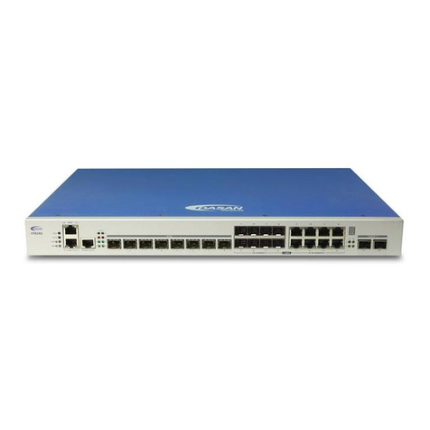
Eci Telecom NPT-1020 Manual

NPT-1020
Version 4.0
Installation and Maintenance Manual

NPT-1020 Installation and Maintenance Manual
V4.0
Catalog No: X91627
Drawing No: 426006-2346-033-A00
March 2015
1st Edition
ECI's NPT-1200, NPT-1050, NPT-1020, NPT-1021, and NPT-1010 products
comply with CE2.0
standard.
ECI's NPT-1600 product complies with MEF9 and MEF14 standards.
ECI's qualification lab is accredited by A2LA for competence in electrical testing according to
the International Standard ISO IEC 17025-2005 General
Requirements for the Competence of
Testing and Calibration Laboratories.
ECI's management applications run on VMWare virtualization hypervisors.
© Copyright by ECI, 2013-2015. All rights reserved worldwide.
This is a legal agreement between you, the end user, and ECI Ltd. (“ECI”). BY OPENING THE DOCUMENTATION AND/OR DISK PACKAGE, YOU ARE
AGREEING TO BE BOUND BY THE TERMS OF THIS AGREEMENT. IF YOU DO NOT AGREE TO THE TERMS OF THIS AGREEMENT, PROMPTLY RETURN
THE UNOPENED DOCUMENTATION AND/OR DISK PACKAGE AND THE ACCOMPANYING ITEMS (INCLUDING WRITTEN MATERIALS AND BINDERS OR
OTHER CONTAINERS), TO THE PLACE FROM WHICH YOU OBTAINED THEM.
The information contained in the documentation and/or disk is proprietary and is subject to all relevant copyright, patent, and other laws protecting
intellectual property, as well as any specific agreement protecting ECI's rights in the aforesaid information. Neither this document nor the
information contained in the documentation and/or disk may be published, reproduced, or disclosed to third parties, in whole or in part, without
the express prior written permission of ECI. In addition, any use of this document, the documentation and/or the disk, or the information contained
therein for any purposes other than those for which it was disclosed, is strictly forbidden.
ECI reserves the right, without prior notice or liability, to make changes in equipment design or specifications. Information supplied by ECI is
believed to be accurate and reliable. However, no responsibility whatsoever is assumed by ECI for the use thereof, nor for the rights of third parties,
which may be affected in any way by the use and/or dissemination thereof.
Any representation(s) in the documentation and/or disk concerning performance of ECI product(s) are for informational purposes only and are not
warranties of product performance or otherwise, either express or implied. ECI's standard limited warranty, stated in its sales contract or order
confirmation form, is the only warranty offered by ECI.
The documentation and/or disk is provided “AS IS” and may contain flaws, omissions, or typesetting errors. No warranty is granted nor liability
assumed in relation thereto, unless specifically undertaken in ECI's sales contract or order confirmation. Information contained in the
documentation and in the disk is periodically updated, and changes will be incorporated in subsequent editions. If you have encountered an error,
please notify ECI. All specifications are subject to change without prior notice.
The documentation and/or disk and all information contained therein is owned by ECI and is protected by all relevant copyright, patent, and other
applicable laws and international treaty provisions. Therefore, you must treat the information contained in the documentation and disk as any
other copyrighted material (for example, a book or musical recording).
Other Restrictions. You may not rent, lease, sell, or otherwise dispose of the documentation and disk, as applicable. YOU MAY NOT USE, COPY,
MODIFY, OR TRANSFER THE DOCUMENTATION AND/OR DISK OR ANY COPY IN WHOLE OR PART, EXCEPT AS EXPRESSLY PROVIDED IN THIS LICENSE.
ALL RIGHTS NOT EXPRESSLY GRANTED ARE RESERVED BY ECI.
All trademarks mentioned herein are the property of their respective holders.
ECI shall not be liable to you or to any other party for any loss or damage whatsoever or howsoever caused, arising directly or indirectly in connection with this
documentation and/or disk, the information contained therein, its use, or otherwise. Notwithstanding the generality of the aforementioned, you expressly waive any
claim and/or demand regarding liability for indirect, special, incidental, or consequential loss or damage which may arise in respect of the documentation and/or disk
and/or the information contained therein, howsoever caused, even if advised of the possibility of such damages.
The end user hereby undertakes and acknowledges that they read the "Before You Start/Safety Guidelines" instructions (when provided by ECI) and that such
instructions were understood by them.
It is hereby clarified that ECI shall not be liable to you or to any other party for any loss or damage whatsoever or howsoever caused, arising directly or indirectly in
connection with you fulfilling and/or failed to fulfill in whole or in part the "Before You Start/Safety Guidelines" instructions.
All graphics included in this document are for illustrative purposes only and might not correspond with your specific product version.

ECI Telecom Ltd. Proprietary
iii
Contents
1About This Manual ...................................................................................... 1-1
1.1 Intended Audience................................................................................................................. 1-1
1.2 Document Organization......................................................................................................... 1-1
1.3 Notes and Warnings............................................................................................................... 1-1
1.4 Related Documentation......................................................................................................... 1-2
1.5 How to Obtain ECI Technical Documentation ....................................................................... 1-2
1.6 Technical Assistance .............................................................................................................. 1-2
2Introduction ................................................................................................ 2-1
2.1 NPT-1020 Platform Layout..................................................................................................... 2-1
2.2 EXT-2U Expansion Unit .......................................................................................................... 2-2
3Before You Start.......................................................................................... 3-1
3.1 Overview ................................................................................................................................ 3-1
3.1.1 Outline of the Installation Procedure...................................................................................... 3-1
3.2 Site Preparation ..................................................................................................................... 3-3
3.2.1 Environmental Requirements ................................................................................................. 3-3
3.2.2 Physical Location ..................................................................................................................... 3-3
3.2.3 Power Sources......................................................................................................................... 3-4
3.3 Tools and Test Equipment ..................................................................................................... 3-4
3.3.1 Cleaning Optical Connectors ................................................................................................... 3-5
3.4 Installing the NPT-1020 in Racks............................................................................................ 3-5
3.4.1 Installation Plan....................................................................................................................... 3-5
3.4.2 Typical NPT-1020 Installation.................................................................................................. 3-6
3.4.3 Integrating NPT-1020 Platforms and Other Equipment in One Rack...................................... 3-6
3.5 Preparing Cables and Fibers .................................................................................................. 3-7
3.5.1 Grounding Cables .................................................................................................................... 3-8
3.5.2DC Power Cables ..................................................................................................................... 3-8
3.5.3 Alarm Cables ........................................................................................................................... 3-9
3.5.4 Management Cables ............................................................................................................... 3-9
3.5.5 Timing (Clock) Cables .............................................................................................................. 3-9
3.5.6 TOD/1PPS Cable .................................................................................................................... 3-10
3.5.7 Electric Traffic Cables ............................................................................................................ 3-10
3.5.8 Optical Fibers......................................................................................................................... 3-11
3.6 Work and Equipment Safety................................................................................................ 3-12

NPT-1020 Installation and Maintenance Manual Contents
ECI Telecom Ltd. Proprietary
iv
3.6.1 Grounding Requirements...................................................................................................... 3-12
3.6.2 DC Power Supply Requirements ........................................................................................... 3-13
3.6.3 AC Power Supply Requirements............................................................................................ 3-14
3.6.4 Laser Safety Requirements.................................................................................................... 3-14
3.7 Protection against Electrostatic Discharge .......................................................................... 3-17
3.7.1 Personnel Training ................................................................................................................ 3-18
3.7.2 Use of a Temporary EPA........................................................................................................ 3-18
3.7.3 Work Arrangements within a Temporary EPA ...................................................................... 3-19
3.8 Environmental and Health Concerns ................................................................................... 3-20
4Installing Equipment ................................................................................... 4-1
4.1 Overview................................................................................................................................ 4-1
4.2 Preliminary Preparations ....................................................................................................... 4-1
4.3 Installation Sequence............................................................................................................. 4-1
4.4 Unpacking and Performing Visual Inspection........................................................................ 4-3
4.5 Installation Options................................................................................................................ 4-4
4.6 Installing Ancillary Units in Racks........................................................................................... 4-6
4.6.1 Installing the RAP-BG .............................................................................................................. 4-6
4.6.2 Installing the RAP-4B ............................................................................................................. 4-12
4.6.3 Installing the FST ................................................................................................................... 4-18
4.6.4 Installing the ODF .................................................................................................................. 4-20
4.6.5 Installing the xDDF-21 Patch Panel ....................................................................................... 4-22
4.6.6 Installing SM_10E/EM_10E ICPs............................................................................................ 4-22
4.6.7 Installing the AC_CONV_UNIT............................................................................................... 4-23
4.7 Installing the NPT-1020 Shelf in the Rack ............................................................................ 4-24
4.7.1 Installing the Rail Stiffeners................................................................................................... 4-24
4.7.2 Attaching the NPT-1020 Shelf in the Rack............................................................................. 4-25
4.7.3 Grounding the NPT-1020 Shelf.............................................................................................. 4-25
4.7.4 Installing Power Modules in the NPT-1020 ........................................................................... 4-26
4.7.5 Installing Tslot Modules ........................................................................................................ 4-29
4.7.6 Installing SFP Modules .......................................................................................................... 4-30
4.8 Installing the EXT-2U Platform in the Rack .......................................................................... 4-31
4.8.1 Installing the H Connector..................................................................................................... 4-32
4.8.2 Installing the EXT-2U Shelf on the NPT-1020 Shelf ............................................................... 4-32
4.8.3 Disassembling the EXT-2U from the NPT-1020 ..................................................................... 4-34
4.8.4 Attaching the EXT-2U Shelf to the Rack ................................................................................ 4-35
4.8.5 Identifying Slots in the EXT-2U .............................................................................................. 4-36

NPT-1020 Installation and Maintenance Manual Contents
ECI Telecom Ltd. Proprietary
v
4.8.6 Installing an FCU_E2U in the EXT-2U..................................................................................... 4-37
4.8.7 Installing Extension Cards in the EXT-2U............................................................................... 4-37
4.8.8 Installing a Power Module in the EXT-2U.............................................................................. 4-39
4.8.9 Installing Traffic Modules in the SM_10E/EM_10E ............................................................... 4-39
4.9 Connecting Fibers and Cables to the NPT-1020 Shelf.......................................................... 4-41
4.9.1 Connecting Power Cables to a DC Power Source.................................................................. 4-41
4.9.2 Connecting an AC Power Cable to the NPT-1020.................................................................. 4-42
4.9.3 Connecting Optical Fibers to Optical Modules...................................................................... 4-42
4.9.4 Routing and Connecting Electrical Interface Cables to the NPT-1020 .................................. 4-43
4.9.5 Routing and Connecting Data Interface Cables to Ethernet Interfaces ................................ 4-48
4.9.6 Routing and Connecting Electrical Cables for PCM Interfaces .............................................. 4-49
4.9.7 Connecting the Timing (Clock) Cable .................................................................................... 4-52
4.9.8 Connecting the TOD/1PPS Timing Cable ............................................................................... 4-52
5NPT-1020 Wall-Mounted Installations......................................................... 5-1
5.1 Overview................................................................................................................................ 5-1
5.2 Wall-Mounted Cabinet .......................................................................................................... 5-1
5.3 Installing the NPT-1020 in a Wall-Mounted Cabinet ............................................................. 5-2
5.4 Installing the Interior Components........................................................................................ 5-2
5.4.1 Preparing the Rear Panel Holes............................................................................................... 5-3
5.4.2 Installing the Rear Panel.......................................................................................................... 5-5
5.4.3 Attaching the Support Rails..................................................................................................... 5-6
5.4.4 Installing the 19" Vertical Extrusions ...................................................................................... 5-6
5.4.5 Installing the C-Rail.................................................................................................................. 5-7
5.5 Installing Cabling Accessories ................................................................................................ 5-7
5.5.1 Installing Cable Guides ............................................................................................................ 5-8
5.5.2 Attaching Cable Clamping Bars ............................................................................................. 5-10
5.5.3 Attaching the Fiber Guide Tube ............................................................................................ 5-10
5.5.4 Installing Grounding Cables................................................................................................... 5-10
5.6 DDF 21 E1s Unit ................................................................................................................... 5-11
5.6.1 Assembling the DDF .............................................................................................................. 5-11
5.6.2 Wiring the E1 Cables to the DDF ........................................................................................... 5-13
5.7 Installing the NPT-1020 and Three DDFs ............................................................................. 5-14
5.7.1 Installing Clip Nuts for the NPT and DDFs ............................................................................. 5-15
5.7.2 Installing the NPT-1020 Platform .......................................................................................... 5-16
5.7.3 Installing the DDFs................................................................................................................. 5-16
5.8 Installing the NPT-1020, Two DDFs, and an AC CONV Unit ................................................. 5-16

NPT-1020 Installation and Maintenance Manual Contents
ECI Telecom Ltd. Proprietary
vi
5.8.1 Installing Clip Nuts for the NPT-1020, DDFs, and AC CONV Unit .......................................... 5-17
5.8.2 Installing the NPT-1020 Platform .......................................................................................... 5-18
5.8.3 Installing DDFs....................................................................................................................... 5-18
5.8.4 Installing the AC CONV Unit .................................................................................................. 5-18
5.9 Connecting Cabinet Grounding............................................................................................ 5-18
5.10 Routing and Connecting Cables and Fibers in the Cabinet.................................................. 5-19
5.10.1 Connecting Power Cables...................................................................................................... 5-20
5.10.2 Connecting Alarm Cables ...................................................................................................... 5-22
5.10.3 Connecting Optical Fibers ..................................................................................................... 5-23
5.10.4 Routing and Connecting Electrical Traffic Cables .................................................................. 5-23
5.10.5 Routing and Connecting Coaxial Cables ................................................................................ 5-24
5.10.6 Connecting Timing (Clock) Cables ......................................................................................... 5-25
5.10.7 Connecting Management Cables .......................................................................................... 5-25
5.11 Connecting Fibers and Cables to the NPT-1020 in Wall-Mounted Cabinet......................... 5-25
5.12 Installing the Wall-Mounted Cabinet Covers and Door....................................................... 5-26
5.12.1 Installing the Top and Bottom Covers................................................................................... 5-26
5.12.2 Installing the Side Covers ...................................................................................................... 5-27
5.12.3 Installing the Front Door ....................................................................................................... 5-28
5.13 Wall-Mounted Frame........................................................................................................... 5-29
5.14 Installing the Wall-Mounted Frame..................................................................................... 5-29
5.14.1 Installing Cable Supports....................................................................................................... 5-29
5.14.2 Attaching the Fiber Guide Tube ............................................................................................ 5-31
5.14.3 Preparing Installation Holes .................................................................................................. 5-31
5.14.4 Attaching the Wall-Mounted Frame ..................................................................................... 5-32
5.15 Installing the NPT-1020 and Accessories in the Wall-Mounted Frame ............................... 5-32
5.15.1 Installing the NPT-1020 and Three DDFs (Option 1) ............................................................. 5-33
5.15.2 Installing the NPT-1020, a DDF, and a RAP-BG (Option 2) .................................................... 5-34
5.15.3 Installing the NPT-1020, a DDF, and an AC/DC CONV (Option 4).......................................... 5-34
5.15.4 Installing the NPT-1020 and a DDF (Option 5) ...................................................................... 5-35
5.16 Installing the Wall-Mounted Frame Front Cover................................................................. 5-35
5.16.1 Installing the Cover Holders .................................................................................................. 5-36
5.16.2 Attaching the Transparent Protection Cover ........................................................................ 5-37
5.17 Connecting Wall-Mounted Frame Grounding ..................................................................... 5-37
5.18 Routing and Connecting Cables and Fibers in the Frame .................................................... 5-38
5.18.1 Connecting Power Cables...................................................................................................... 5-39
5.18.2 Connecting Alarm Cables ...................................................................................................... 5-40
5.18.3 Connecting Optical Fibers ..................................................................................................... 5-40

NPT-1020 Installation and Maintenance Manual Contents
ECI Telecom Ltd. Proprietary
vii
5.18.4 Routing and Connecting Electrical Traffic Cables .................................................................. 5-41
5.18.5 Routing and Connecting Coaxial Cables ................................................................................ 5-41
5.18.6 Connecting Timing (Clock) Cables ......................................................................................... 5-42
5.18.7 Connecting Management Cables .......................................................................................... 5-42
6Commissioning Tests ................................................................................... 6-1
6.1 Test Equipment...................................................................................................................... 6-1
6.2 Site Commissioning Tests ...................................................................................................... 6-1
6.2.1 Checking Cards and Modules Installed in Each Shelf .............................................................. 6-1
6.2.2 Visual Inspection and Mechanical Checks............................................................................... 6-2
6.2.3 Measuring Optical Levels ........................................................................................................ 6-3
6.2.4 Platform Power-On Test Procedure ........................................................................................ 6-4
6.3 SDH Commissioning Tests...................................................................................................... 6-4
6.3.1 Test Equipment Setup ............................................................................................................. 6-4
6.3.2 Network Timing Synchronization Test .................................................................................... 6-5
6.3.3 Loss of Signal (LOS) Detection Test ......................................................................................... 6-6
6.3.4 Input Sensitivity Test ............................................................................................................... 6-6
6.3.5 Equipment Power-On Test ...................................................................................................... 6-6
6.3.6 Traffic Stability Test................................................................................................................. 6-7
6.3.7 Path Protection and Nonretrieval Test.................................................................................... 6-7
6.3.8 Severity Assignment Test ........................................................................................................ 6-8
6.3.9 Transmission Alarm-Handling Test.......................................................................................... 6-8
6.3.10 Maintenance Action Test ........................................................................................................ 6-9
6.4 Data Network Commissioning Tests...................................................................................... 6-9
6.4.1 Throughput and Latency Tests ................................................................................................ 6-9
6.4.2 System Recovery and Reset Tests ......................................................................................... 6-10
6.4.3 Frame Loss Rate Test............................................................................................................. 6-10
6.4.4 Stability Test .......................................................................................................................... 6-11
6.4.5 Alarm-Handling Test.............................................................................................................. 6-11
7Maintenance ............................................................................................... 7-1
7.1 Overview................................................................................................................................ 7-1
7.2 Test Equipment, Tools, and Materials ................................................................................... 7-1
7.3 Preventive Maintenance........................................................................................................ 7-1
7.4 Onsite Troubleshooting ......................................................................................................... 7-2
7.4.1 Troubleshooting Power Problems........................................................................................... 7-3
7.4.2 Troubleshooting Using Component Indicators ....................................................................... 7-4
7.5 Replacing Cards and Modules.............................................................................................. 7-14

NPT-1020 Installation and Maintenance Manual Contents
ECI Telecom Ltd. Proprietary
viii
7.5.1 Safety and Workmanship ...................................................................................................... 7-14
7.5.2 Replacing Tslot Cards ............................................................................................................ 7-15
7.5.3 Replacing Eslot Cards ............................................................................................................ 7-16
7.5.4 Replacing Traffic Modules on the SM_10E/EM_10E............................................................. 7-16
7.5.5 Replacing ICPs for the SM_10E/EM_10E............................................................................... 7-17
7.5.6 Replacing Power Modules..................................................................................................... 7-17
7.5.7 Replacing SFP/CSFP/SFP+ Transceivers................................................................................. 7-18
8Connection Data.......................................................................................... 8-1
8.1 Overview................................................................................................................................ 8-1
8.2 INF-B1U/INF-B1U-D/INF-E2U DC Input Power Connectors ................................................... 8-1
8.3 AC_PS-B1U/AC_PS-E2U AC Input Power Connectors ............................................................ 8-1
8.4 T3/T4 Timing Connector ........................................................................................................ 8-2
8.5 1PPS/ToD Timing Connector.................................................................................................. 8-3
8.6 Alarms Connector .................................................................................................................. 8-3
8.7 E1 Connectors on the PME1_21 and MSE1_16 ................................................................... 8-10
8.8 Ethernet Interface Connectors ............................................................................................ 8-14
8.9 PM345_3 Card Connection Data ......................................................................................... 8-15
8.10 P345_3E Card Connection Data........................................................................................... 8-15
8.11 PE1_63 Card Connection Data ............................................................................................. 8-15
8.12 SM_10E/EM_10E Card Connection Data............................................................................. 8-21
8.12.1 Connection Data for SM_FXO_8E and SM_FXS_8E Interfaces.............................................. 8-21
8.12.2 Connection Data for SM_EM_24W6E Interfaces .................................................................. 8-22
8.12.3 Connection Data for SM_V24E Interfaces............................................................................. 8-24
8.12.4 Connection Data for SM_V35_V11 Interfaces ...................................................................... 8-27
8.12.5 Connection Data for SM_CODIR_4E Interfaces..................................................................... 8-29
8.12.6 Connection Data for SM_OMNI_E Interfaces ....................................................................... 8-30
8.13 ICP_VF Connection Data ...................................................................................................... 8-32
8.14 ICP_V24 Connection Data.................................................................................................... 8-33
8.15 ICP_V35 Connection Data.................................................................................................... 8-35
8.16 ICP_V11_V24 Connection Data............................................................................................ 8-36
8.17 ICP_DB37D Connection Data ............................................................................................... 8-38
8.18 RAP-4B Connectors .............................................................................................................. 8-42
8.18.1 SHELF ALARM Connectors..................................................................................................... 8-42
8.18.2 ALARM IN/OUT Connector.................................................................................................... 8-43

NPT-1020 Installation and Maintenance Manual Contents
ECI Telecom Ltd. Proprietary
ix
9Rack Installation.......................................................................................... 9-1
9.1 Installing Equipment Racks .................................................................................................... 9-1
9.1.1 Marking Rack Floor.................................................................................................................. 9-1
9.1.2 Installing the Rack on Concrete Floors .................................................................................... 9-2
9.1.3 Installing the Rack on Wooden Floors..................................................................................... 9-2
9.1.4 Installing the Rack on Floating (Suspended) Floors................................................................. 9-4
9.1.5 Installing the Rack on Suspended Overhead Trays ................................................................. 9-5
9.1.6 Installing Extendable Rails....................................................................................................... 9-5
9.1.7 Grounding the Rack................................................................................................................. 9-5
9.2 Installing 19" Racks ................................................................................................................ 9-6

ECI Telecom Ltd. Proprietary
x
List of Figures
Figure 2-1: NPT-1020 platform....................................................................................................................... 2-1
Figure 2-2: NPT-1020 platform with expansion unit ...................................................................................... 2-2
Figure 2-3: EXT-2U platform ........................................................................................................................... 2-2
Figure 2-4: EXT-2U slot layout ........................................................................................................................ 2-3
Figure 3-1: Typical installation of four NPT-1020 platforms in an ETS........................................................... 3-7
Figure 3-2: Laser warning label..................................................................................................................... 3-15
Figure 3-3: Basic ESD warning symbol.......................................................................................................... 3-17
Figure 3-4: Pollution control logos ............................................................................................................... 3-21
Figure 3-5: WEEE recycling symbol............................................................................................................... 3-21
Figure 4-1: Typical installation in of a single NPT-1020 in an 2200 ETSI rack................................................. 4-2
Figure 4-2: Typical installation of four NPT-1020 platforms in an ETSI 2200 rack ......................................... 4-5
Figure 4-3: Location of RAP-BG grounding stud ............................................................................................. 4-8
Figure 4-4: Identification of RAP-BG cable routes.......................................................................................... 4-8
Figure 4-5: Connecting DC power cables to the RAP-BG................................................................................ 4-9
Figure 4-6: RAP-BG platform power cable grounding screws ...................................................................... 4-10
Figure 4-7: RAP-BG front cover removal ...................................................................................................... 4-10
Figure 4-8: RAP-BG circuit breaker installation ............................................................................................ 4-11
Figure 4-9: Platform DC input power connector pin functions .................................................................... 4-11
Figure 4-10: Locating RAP-4B grounding stud.............................................................................................. 4-13
Figure 4-11: RAP-4B with grounding cable................................................................................................... 4-14
Figure 4-12: Identifying RAP-4B cable routes............................................................................................... 4-14
Figure 4-13: Connecting DC power cables to the RAP-4B ............................................................................ 4-15
Figure 4-14: RAP-4B platform power cable grounding screws..................................................................... 4-16
Figure 4-15: RAP-4B front cover removal..................................................................................................... 4-17
Figure 4-16: RAP-4B circuit breaker installation........................................................................................... 4-17
Figure 4-17: Platform DC input power connector pin functions.................................................................. 4-18
Figure 4-18: Threading optical fibers in the FST........................................................................................... 4-19
Figure 4-19: Attaching rack mounting brackets to the ODF......................................................................... 4-20
Figure 4-20: ODF front panel........................................................................................................................ 4-20
Figure 4-21: ODF open view ......................................................................................................................... 4-21
Figure 4-22: ODF fiber routes....................................................................................................................... 4-21
Figure 4-23: Installing SM_10E/EM_10E ICPs in the rack............................................................................. 4-23
Figure 4-24: Installing the AC_CONV_UNIT in the rack................................................................................ 4-24
Figure 4-25: Installing an INF-B1U in the NPT-1020 ..................................................................................... 4-26
Figure 4-26: Installing an INF-B1U-24V in the NPT-1020 ............................................................................. 4-27
Figure 4-27: Installing an INF-B1U-D in the NPT-1020 ................................................................................. 4-28
Figure 4-28: Installing an AC_PS-B1U in the NPT-1020 ................................................................................ 4-29
Figure 4-29: Installing Tslot modules in the NPT-1020................................................................................. 4-30
Figure 4-30: Installing an SFP in the NPT-1020............................................................................................. 4-31
Figure 4-31: Installing the H connector in the NPT-1020 ............................................................................. 4-32

NPT-1020 Installation and Maintenance Manual List of Figures
ECI Telecom Ltd. Proprietary
xi
Figure 4-32: Removing the EXT-2U from the NPT-1020............................................................................... 4-34
Figure 4-33: Inserting the thin flat-head tool............................................................................................... 4-34
Figure 4-34: Raising the rivet cap ................................................................................................................. 4-35
Figure 4-35: Removing the rivet ................................................................................................................... 4-35
Figure 4-36: EXT-2U regular slots layout ...................................................................................................... 4-36
Figure 4-37: EXT-2U slot layout with extended ES 3# .................................................................................. 4-36
Figure 4-38: Installing an FCU_E2U in the EXT-2U ....................................................................................... 4-37
Figure 4-39: Installing an extension card in the EXT-2U............................................................................... 4-38
Figure 4-40: Installing a power module in the EXT-2U................................................................................. 4-39
Figure 4-41: Installing traffic module in the SM_10E/EM_10E .................................................................... 4-40
Figure 4-42: PME1_63 traffic cable .............................................................................................................. 4-45
Figure 4-43: PME1_63 traffic cable installation ........................................................................................... 4-47
Figure 5-1: Wall-mounted cabinet general view ............................................................................................ 5-1
Figure 5-2: Wall-mounted cabinet interior components ............................................................................... 5-3
Figure 5-3: Preparing the rear panel holes..................................................................................................... 5-4
Figure 5-4: Tools required for cabinet installation......................................................................................... 5-4
Figure 5-5: Installing the rear panel ............................................................................................................... 5-5
Figure 5-6: Installing the support rails............................................................................................................ 5-6
Figure 5-7: Installing the 19" vertical extrusions............................................................................................ 5-6
Figure 5-8: Installing the C-rail ....................................................................................................................... 5-7
Figure 5-9: Cabling accessories installed in the cabinet................................................................................. 5-8
Figure 5-10: Cabling accessories..................................................................................................................... 5-9
Figure 5-11: DDF general view...................................................................................................................... 5-11
Figure 5-12: Installing the brackets for ETSI installation .............................................................................. 5-12
Figure 5-13: Attaching the connection blocks.............................................................................................. 5-13
Figure 5-14: Installing an NPT-1020 platform and three DDFs..................................................................... 5-14
Figure 5-15: Clip nuts distance in mm (NPT-1020 and three DDFs)............................................................. 5-15
Figure 5-16: Clip nuts distance in mm (NPT-1020, two DDFs, AC CONV unit) ............................................. 5-17
Figure 5-17: Wall-mounted cabinet cabling ................................................................................................. 5-20
Figure 5-18: Wall-mounted cabinet cables routing front view .................................................................... 5-21
Figure 5-19: Wall-mounted cabinet cables routing left side view ............................................................... 5-22
Figure 5-20: Installing top and bottom covers ............................................................................................. 5-26
Figure 5-21: Connecting grounding cables ................................................................................................... 5-27
Figure 5-22: Installing side covers ................................................................................................................ 5-27
Figure 5-23: Connecting grounding cables ................................................................................................... 5-28
Figure 5-24: Installing the front door ........................................................................................................... 5-28
Figure 5-25: Connecting the door grounding cable...................................................................................... 5-29
Figure 5-26: Wall-mounted frame installation............................................................................................. 5-30
Figure 5-27: Attaching the fiber guide tube ................................................................................................. 5-31
Figure 5-28: Installing a NPT-1020 and three DDFs...................................................................................... 5-33
Figure 5-29: Installing the front cover.......................................................................................................... 5-36

NPT-1020 Installation and Maintenance Manual List of Figures
ECI Telecom Ltd. Proprietary
xii
Figure 5-30: Routing and connecting cables and fibers in the wall-mounted frame................................... 5-38
Figure 5-31: Wall-mounted frame cable routing - left side view ................................................................. 5-39
Figure 7-1: Inserting an SFP/CSFP/SFP+ transceiver into a module ............................................................. 7-18
Figure 8-1: POWER IN input power connector, pin functions........................................................................ 8-1
Figure 8-2: AC input power connector ........................................................................................................... 8-1
Figure 8-3: T3/T4 connector, pin identification.............................................................................................. 8-2
Figure 8-4: 1PPS/ToD connector, pin identification ....................................................................................... 8-3
Figure 8-5: Alarms connector, pin identification............................................................................................ 8-4
Figure 8-6: E1 connectors for PME1_21, pin identification.......................................................................... 8-11
Figure 8-7: Ethernet connector, pin identification....................................................................................... 8-14
Figure 8-8: Typical E1 connector for PE1_63, pin identification .................................................................. 8-15
Figure 8-9: SM_10E/EM_10E traffic module connector, pin identification ................................................. 8-21
Figure 8-10: 25-pin D-type male connector, pin identification.................................................................... 8-33
Figure 8-11: 9-pin D-type male connector, pin identification...................................................................... 8-34
Figure 8-12: M34 female connector, pin identification ............................................................................... 8-35
Figure 8-13: 15-pin D-type female connector, pin identification................................................................. 8-36
Figure 8-14: 25-pin D-type male connector, pin identification.................................................................... 8-37
Figure 8-15: 37-pin D-type female connector, pin identification................................................................. 8-38
Figure 8-16: RAP-4B SHELF ALARM connector, pin identification................................................................ 8-42
Figure 8-17: RAP-4B ALARM IN/OUT connector, pin identification ............................................................. 8-44
Figure 9-1: Mounting diagrams for ETSI racks................................................................................................ 9-3
Figure 9-2: Mounting diagrams for 19" and 23" racks ................................................................................... 9-4
Figure 9-3: Rack mounting diagram for attachment to suspended overhead tray (2200 mm
rack).............................................................................................................................................. 9-5
Figure 9-4: Example of an approved European 19” rack................................................................................ 9-6
List of Tables
Table 3-1: Typical NPT-1020 equipment installation sequence ..................................................................... 3-1
Table 3-2: Environmental requirements ........................................................................................................ 3-3
Table 3-3: Equipment dimensions.................................................................................................................. 3-4
Table 3-4: Recommended coaxial cable assembly tools ................................................................................ 3-4
Table 3-5: Traffic cables mating connector data for NPT-1020.................................................................... 3-10
Table 3-6: Traffic cables mating connector data for EXT-2U........................................................................ 3-11
Table 3-7: Optical fibers and mating connector data for NPT-1020 ............................................................ 3-11
Table 3-8: Optical fibers and mating connector data for EXT-2U ................................................................ 3-12
Table 3-9: NPT-1020 and EXT-2U circuit breaker data................................................................................. 3-14
Table 3-10: NPT-1020 and EXT-2U recommended circuit breakers............................................................. 3-14
Table 3-11: LC transceivers laser information STM-4 SFP ............................................................................ 3-16
Table 3-12: LC transceivers laser information STM-1/100BaseFX SFP......................................................... 3-16
Table 3-13: LC transceivers laser information GbE SFP (OTGBE) ................................................................. 3-17
Table 4-1: Outline of typical NPT-1020 equipment installation sequence..................................................... 4-3
Table 4-2: EXT-2U modules .......................................................................................................................... 4-36

NPT-1020 Installation and Maintenance Manual List of Figures
ECI Telecom Ltd. Proprietary
xiii
Table 6-1: Card and module inventory........................................................................................................... 6-2
Table 6-2: Visual inspection and mechanical checks...................................................................................... 6-2
Table 6-3: Measured optical levels................................................................................................................. 6-3
Table 6-4: 2 Mbps tests .................................................................................................................................. 6-4
Table 6-5: 34 Mbps tests ................................................................................................................................ 6-4
Table 6-6: 45 Mbps tests ................................................................................................................................ 6-5
Table 6-7: SDH tests........................................................................................................................................ 6-5
Table 6-8: Traffic stability test time intervals................................................................................................. 6-7
Table 6-9: Throughput and latency test results ........................................................................................... 6-10
Table 6-10: Frame loss rate test results ....................................................................................................... 6-11
Table 7-1: Preventive maintenance inspection and checks ........................................................................... 7-1
Table 7-2: Troubleshooting power problems................................................................................................. 7-3
Table 7-3: General troubleshooting procedures for NPT-1020 power-on..................................................... 7-5
Table 7-4: General troubleshooting procedures for NPT-1020...................................................................... 7-8
Table 7-5: General troubleshooting procedures for optical transceiver plug-ins .......................................... 7-9
Table 7-6: Troubleshooting procedures for PME1_21/PME1_63/DMCES1_4/MSE1_16 cards................... 7-11
Table 7-7: Troubleshooting procedures for SMD1B/SMS4 cards................................................................. 7-12
Table 7-8: General troubleshooting procedures for extended cards PE1_63/P345_3E/
SM_10E/EM_10E/S1_4/P345_3E/DMCE1_32........................................................................... 7-12
Table 7-9: Special troubleshooting procedures for P345_3E cards ............................................................. 7-13
Table 7-10: General troubleshooting procedures for daughterboards on SM_10E/EM_10E cards ............ 7-14
Table 8-1: T3/T4 connector, PIN identification .............................................................................................. 8-2
Table 8-2: 1PPD/ToD connector, PIN identification ....................................................................................... 8-3
Table 8-3: Alarms connector, pin assignment ................................................................................................ 8-4
Table 8-4: PME1_21 and MSE1_16 connector, pin assignment................................................................... 8-11
Table 8-5: Ethernet connector, pin assignment ........................................................................................... 8-14
Table 8-6: PE1_63 typical E1 connector (P2), pin assignment ..................................................................... 8-15
Table 8-7: PE1_63 typical connector (P1), pin assignment .......................................................................... 8-18
Table 8-8: SM_10E/EM_10E SM_FXO_8 and SM_FXS_8 connector, pin assignment.................................. 8-21
Table 8-9: SM_10E/EM_10E SM_EM_24W6E connector, pin assignment .................................................. 8-22
Table 8-10: SM_10E/EM_10E SM_V24E connector, pin assignment for 8 x V.24 transparent
without controls mode .............................................................................................................. 8-24
Table 8-11: SM_V24E connector, pin assignment........................................................................................ 8-25
Table 8-12: SM_10E/EM_10E SM_V24E connector, pin assignment for 2 x V.24 synchronous
with controls mode.................................................................................................................... 8-26
Table 8-13: SM_10E/EM_10E SM_V35_V11 connector, pin assignment .................................................... 8-27
Table 8-14: SM_V35_V11 pin assignment per interface type...................................................................... 8-28
Table 8-15: SM_10E/EM_10E SM_CODIR_4E connector, pin assignment................................................... 8-29
Table 8-16: SM_10E/EM_10E SM_OMNI_E connector, pin assignment ..................................................... 8-30
Table 8-17: ICP_VF RJ-45 connector, pin assignment for serving SM_FXS_8E or SM_FXO_8E ................... 8-32
Table 8-18: ICP_VF RJ-45 connector, pin assignment for serving SM_EM_24W6E ..................................... 8-32
Table 8-19: ICP_VF RJ-45 connector, pin assignment for serving SM_CODIR_4E........................................ 8-33

NPT-1020 Installation and Maintenance Manual List of Figures
ECI Telecom Ltd. Proprietary
xiv
Table 8-20: ICP_V24 synchronous V.24 25-pin D-type connector, pin assignment ..................................... 8-33
Table 8-21: ICP_V24 asynchronous V.24 9-pin D-type connector, pin assignment ..................................... 8-34
Table 8-22: ICP_V24 transparent V.24 9-pin D-type connector, pin assignment......................................... 8-35
Table 8-23: ICP_V35 M34 female connector, pin assignment ..................................................................... 8-35
Table 8-24: ICP_V11_V24 15-pin D-type connector, pin assignment .......................................................... 8-36
Table 8-25: ICP_V11_V24 V.24 25-pin D-type connector, pin assignment .................................................. 8-37
Table 8-26: ICP_DB37D 37 pin D-type connector, pin assignment .............................................................. 8-38
Table 8-27: ICP_DB37D 37-pin D-type connector, RS-449 pin assignment.................................................. 8-39
Table 8-28: ICP_DB37D 37-pin D-type connector, RS-422 pin assignment.................................................. 8-40
Table 8-29: ICP_DB37D 37-pin D-type connector, V.36 pin assignment...................................................... 8-40
Table 8-30: ICP_DB37D 37-pin D-type connector, V.35 pin assignment...................................................... 8-40
Table 8-31: ICP_DB37D 37-pin D-type connector, V.11/X.24 pin assignment ............................................. 8-41
Table 8-32: ICP_DB37D 37-pin D-type connector, synchronous V.24 pin assignment ................................ 8-41
Table 8-33: RAP-4B PLATFORM ALARM connector, pin assignment............................................................ 8-42
Table 8-34: RAP-4B ALARM IN/OUT connector, pin assignment ................................................................. 8-44

ECI Telecom Ltd. Proprietary
1-1
1 About This Manual
The NPT-1020 Installation, Operation, and Maintenance Manual (IOMM) describes how to install NPT-1020
platforms and how to install and replace hardware components, including cards, modules, and accessories.
1.1 Intended Audience
The NPT-1020 IMM is intended for installation and other qualified service personnel responsible for
installing the platform and its accessories.
1.2 Document Organization
This manual contains the following information:
Installation
Operation
Maintenance
Additional functionality
1.3 Notes and Warnings
When applicable, this guide uses the following notes and warnings:
NOTE
: clarifying information, specific instructions, commentary, sidelights, or interesting
points of information.
CAUTION: failure to follow
directions could result in damage to equipment or loss of
information.
WARNING: failure to follow directions could result in bodily harm or loss of life.
LASER WARNING
: how to avoid personal injury. All personnel involved in equipment
installation,
operation, and maintenance must be aware that laser radiation is invisible.
Therefore, although protective devices generally prevent direct exposure to the beam,
personnel must strictly observe the applicable safety precautions and, in particular, must
avoid staring into optical connectors, either directly or using optical instruments.
ESD
: information on how to avoid discharge of static electricity and subsequent damage to
the unit.

NPT-1020 Installation and Maintenance Manual About This Manual
ECI Telecom Ltd. Proprietary
1-2
TIP: helpful information and handy hints that can make your task easier.
IMPORTANT: essential information to which you must pay attention.
1.4 Related Documentation
The following publications may be of assistance to you in the installation and commissioning processes.
Some of these documents present information supplied in this Installation Manual in greater or lesser
detail.
NPT Product Line General Description
NPT Product Line System Specifications
NPT Product Line Reference Manual
EMS-APT User Manual
LCT-APT User Manual
LightSoft® Network Management System User Manual
IEC Publication 825 - Laser Safety Requirements
1.5 How to Obtain ECI Technical Documentation
To obtain technical documentation related to any ECI product, contact:
ECI Telecom Ltd.
ECI Documentation Group
30 Hasivim St.
Petach Tikva 4959388 – Israel
Fax: +972-3-9268060
Email: techdoc.feedback@ecitele.com
1.6 Technical Assistance
The configuration, installation, and operation of NPT series and its operation in a network are highly
specialized processes. Due to the different nature of each installation, some planning aspects might not be
covered in this manual.
If you have questions or concerns about your network design or if you require installation personnel to
perform the actual installation process, ECI maintains a staff of design engineers and highly trained field
service personnel. The services of this group are available to customers at any time.

NPT-1020 Installation and Maintenance Manual About This Manual
ECI Telecom Ltd. Proprietary
1-3
To obtain design assistance or a network installation plan from ECI's Customer Support team, contact your
ECI sales representative. With any support related issues, technical or logistic, please contact the ECI
Customer Support center at your location. If you are not familiar with that location, or contact our
Customer Support Center action line at:
Telephone +972-3-9266000
Telefax +972-3-9266370
Email on.support@ecitele.com

ECI Telecom Ltd. Proprietary
2-1
2 Introduction
2.1 NPT-1020 Platform Layout
The NPT-1020 is a packet transport platform for the access, offering an All-Native solution that optimizes
both TDM and packet handling. The NPT-1020 is a cost-effective choice for the first aggregation stage,
geared for cellular tail locations (3G and LTE), providing a unique hybrid solution for high capacity access
rings, and optimized for popular triple play applications.
As Packet Optical Access (POA) platform with enhanced MPLS-TP support, the NPT-1020 is designed around
a centralized hybrid matrix card that supports any-to-any direct data card connectivity as well as native
TDM switching capacity. The NPT-1020 offers a packet switching capacity of up to 10 Gbps or 60 Gbps (with
a choice of two modes on the same unit) as well as a TDM capacity of up to 2.5G (16 x VC4 fully low order
traffic).
The platform offers non-traffic-affecting upgrades from 1G-based configurations to 10GE-based (with up to
4 x 10GE interfaces) through the CPS50 card, a central packet switch (CPS) Tslot card for the NPT-1020. This
card provides scalable upgrade with high capacity 10GE configuration to the NPT-1020. The CPS50 makes it
possible to upgrade the system packet switching capacity to 60 Gbps, supporting up to 2 × 10GE (SFP+) and
2 flexible SFP houses (each can support 1 × 10GE with SFP+, or 1 × GE with SFP, or 2 × GE with CSFP).
The NPT-1020 offers enhanced MPLS-TP data network functionality, including the complete range of
Ethernet-based services (CES, EoS, MoT, MoE, and PoE+) (see MPLS-TP and Ethernet Solutions).
The NPT-1020 is a compact (1U) base platform housed in a 243 mm deep, 465 mm wide, and 44 mm high
equipment cage with all interfaces accessible from the front of the unit. The platform includes the following
components:
Traffic processing modules:
21 built-in native E1s
14 ports, divided between:
2 x STM1/STM4 ports (native)
4 x 10/100/1000BaseT electrical ports (PoE+)
4 x 10/100/1000BaseT electrical ports
4 100/1000 FX/GE optical ports
1 traffic card slot (Tslot)
Compact flash card (NVM)
Traffic connector to the (optional) EXT-2U expansion unit
Timing module (T3/T4, ToD and 1pps)
Redundant or non-redundant power supply modules (INF)
Figure 2-1: NPT-1020 platform

NPT-1020 Installation and Maintenance Manual Introduction
ECI Telecom Ltd. Proprietary
2-2
The NPT-1020 can be fed by 24 VDC, -48 VDC, or 94-240 VAC. In DC power feeding, two INF modules can be
configured in two power supply module slots for redundant power supply, or one double slot INF module
with dual-feeding can be configured. AC power feeding requires the use of a conversion module to
implement AC/DC conversion.
The NPT-1020 can be installed in 2,200 mm or 2,600 mm ETSI racks or in 19” racks. The rugged platform
design also makes this platform suitable for street cabinet use, withstanding temperatures up to 70°C.
The NPT-1020 can also be configured as an expanded platform, when combined with the EXT-2U expansion
unit, as illustrated in the following figure.
Figure 2-2: NPT-1020 platform with expansion unit
Typical power consumption for the NPT-1020 is 50 W. Power consumption is monitored through the
management software. For more information about power consumption requirements, see the NPT
Installation and Maintenance Manual and the NPT System Specifications.
2.2 EXT-2U Expansion Unit
The EXT-2U platform is a high density modular expansion unit for the NPT's multiservice metro access
platform series. It supports the complete range of native and hybrid PCM, TDM, PDH, SDH, and Ethernet
interfaces. All traffic processing, cross-connect, packet switching, timing and synchronization, control and
communication and main power supply functions are performed by the corresponding system in the base
unit on which expansion unit is installed. Integrating this add-on platform into your network configuration
is not traffic-affecting.
NOTE: The EXT-2U expansion unit can be combined with the NPT-1020, NPT-1021, NPT-1050,
NPT-1200, and NPT-
1800 platforms. For easier reading, the slot layout is not repeated in the
sections describing each of those platforms. The reader is simply referred back to this slot
layout description.
Figure 2-3: EXT-2U platform
The EXT-2U expansion unit is housed in a 243 mm deep, 465 mm wide, and 88 mm high equipment cage
with all interfaces accessible from the front of the unit. Expansion units include their own independent
power supply and fan unit, for additional reliability and security. The platform includes the following
components:

NPT-1020 Installation and Maintenance Manual Introduction
ECI Telecom Ltd. Proprietary
2-3
Three multipurpose slots (ES1 to ES3) for any combination of extractable traffic cards. PCM, TDM,
ADM, Ethernet, and CES traffic are all handled through cards in these traffic slots. All interfaces are
configured through convenient SFP modules, supporting up to 2.5G or 2GbE traffic per slot. Each slot
in the EXT-2U has a TDM capacity of up to 16 x VC-4s; the total capacity of the EXT-2U is 48 x VC-4s.
Two slots for INF power supply units. There are two units for system redundancy. Note that INF
modules are extractable in the EXT-2U.
One FCU fan unit consisting of multiple separate fans to support cooling system redundancy.
The following figure depicts the EXT-2U platform layout.
Figure 2-4: EXT-2U slot layout
Typical power consumption for the EXT-2U is less than 150 W. Power consumption is monitored through
the management software. For more information about power consumption requirements, see the NPT
Installation and Maintenance Manual and the NPT System Specifications.
Table of contents
Other Eci Telecom Network Hardware manuals
Popular Network Hardware manuals by other brands

Comtrend Corporation
Comtrend Corporation WAP-5940 Quick install guide
QNAP
QNAP NVR-101 user manual
ABB
ABB MicroSCADA Pro SYS 600 Technical description
IBM
IBM Proventia Management SiteProtector SP1001 Hardware configuration guide

Safran
Safran SATCORE Series user manual

Atlantis Land
Atlantis Land DiskMaster NASG501D quick start guide
DPS Telecom
DPS Telecom NetGuardian 16A user manual
Symantec
Symantec Shelf NetBackup 5220 Safety guide
Patton electronics
Patton electronics NetLink 2707C user manual
Data Video
Data Video DVP-100 quick start guide
Vivotek
Vivotek ND8401 Quick installation guide

Allied Telesis
Allied Telesis ADSL24AE Specifications
