Citrix ADC MPX User manual

Citrix ADC MPX
Citrix Product Documentation | docs.citrix.com February 8, 2023

Citrix ADC MPX
Contents
Common hardware components 3
Data sheets 21
Citrix ADC MPX hardware‑soware compatibility matrix 21
Hardware platforms 24
Citrix ADC MPX 5500 24
Citrix ADC MPX 5550 and MPX 5650 26
Citrix ADC MPX 5900 27
Citrix ADC MPX 7500 and MPX 9500 29
Citrix ADC MPX 8005, MPX 8015, MPX 8200, MPX 8400, MPX 8600, and MPX 8800 32
Citrix ADC MPX 8900 34
Citrix ADC MPX 8900 FIPS certified appliance 37
Citrix ADC MPX 9100 39
Citrix ADC MPX 9700, MPX 10500, MPX 12500, and MPX 15500 41
Citrix ADC MPX 11500, MPX 13500, MPX 14500, MPX 16500, MPX 18500, and MPX 20500 44
Citrix ADC MPX 11500 46
Citrix ADC MPX 14000 48
Citrix ADC MPX 14000‑40C 51
Citrix ADC MPX 14000‑40G 53
Citrix ADC MPX 14000‑40S 55
Citrix ADC MPX 14000 FIPS 57
Citrix ADC MPX 15000 59
Citrix ADC MPX 15000‑50G 61
Citrix ADC MPX 15000‑50G FIPS certified appliance 64
© 1999–2023 Cloud Soware Group, Inc. All rights reserved. 2

Citrix ADC MPX
Citrix ADC MPX 16000 67
Citrix ADC MPX 17500, MPX 19500, and MPX 21500 70
Citrix ADC MPX 17550, MPX 19550, MPX 20550, and MPX 21550 72
Citrix ADC MPX 22000 74
Citrix ADC MPX 24100 77
Citrix ADC MPX 25000A 79
Citrix ADC MPX 25100T 81
Citrix ADC MPX 25000TA 83
Citrix ADC MPX 25000‑40G 85
Citrix ADC MPX 26000 87
Citrix ADC MPX 26000‑50S 89
Citrix ADC MPX 26000‑100G 92
Citrix ADC T1010 94
Citrix ADC T1100 96
Citrix ADC T1120 98
Citrix ADC T1200 99
Citrix ADC T1300 101
Citrix ADC T1310 103
Citrix Web App Firewall platforms 105
Field replaceable units 105
Safety, cautions, warnings, and other information 122
Taiwan BSMI RoHS statement 128
FCC compliance statement 130
Prepare for installation 131
© 1999–2023 Cloud Soware Group, Inc. All rights reserved. 3

Citrix ADC MPX
Install the hardware 133
Initial configuration 142
Lights out management port of the Citrix ADC MPX appliance 155
Configure the network settings on the LOM port 157
Install a certificate and key on the LOM GUI 162
Obtain the MAC address, serial number, and host properties of the appliance 168
Perform power control operations by using the LOM port 169
Restore the BMC configuration to factory defaults 171
Use the BIOS POST code to detect errors 172
Upgrade the LOM firmware on a Citrix ADC MPX appliance 172
Enable RADIUS authentication in the LOM GUI 174
RAKP topology on Citrix ADC appliances 175
Configure Active Directory in LOM 176
Change the BMC host name 179
Hardware health attributes for the MPX 16000 platform 181
Hardware health attributes for the MPX 9100 platform 186
Hardware health attributes 191
Fortville NICs firmware upgrade on Citrix ADC MPX appliances 204
Wiping your data before sending the ADC appliance to Citrix 207
How to verify the file system integrity of your Citrix ADC MPX appliance 209
Migrate the configuration of an existing Citrix ADC appliance to another Citrix ADC appliance212
Troubleshooting 215
Hardware FAQs 217
© 1999–2023 Cloud Soware Group, Inc. All rights reserved. 4

Citrix ADC MPX
Common hardware components
October 26, 2022
Each platform has front panel and back panel hardware components. The front panel on most appli‑
ances has an LCD display and an RS232 serial console port. The number, type, and location of ports
vary by hardware platform for the following transceivers: copper Ethernet, copper and fiber 1G SFP,
copper 10G Base‑T, 10G SFP+, 40G QSFP+, 50G QSFP28, and 100G QSFP28. The back panel provides
access to the field replaceable units (power supplies and solid‑state drives).
LCD display and LED status indicators
Note
This section does not apply to MPX 9100 and MPX 16000 appliances.
The LCD display on the front of every appliance displays messages about the current operating status
of the appliance. These messages communicate whether your appliance has started properly and
is operating normally. If the appliance is not operating normally, the LCD displays troubleshooting
messages.
The LCD displays live statistics, diagnostic information, and active alerts. The dimensions of the LCD
limit the display to two lines of 16 characters each. As the result, the displayed information flows
through a sequence of screens. Each screen shows information about a specific function.
The LCD has an LED backlight. Normally, the backlight glows steadily. When there is an active alert, it
blinks rapidly. If the alert information exceeds the LCD screen size, the backlight blinks at the begin‑
ning of each display screen. Aer the appliance shuts down, the backlight remains on for one minute
and then automatically turns o.
System status LEDs
On the MPX 22000 and MPX 24000 appliance back panel, system status LEDs indicate the overall status
of the appliance. The following table describes the indicators of the system status LED.
Note: System status LEDs are available on only some Citrix ADC appliances.
LED Color LED Indicates
OFF No power.
Green Appliance is receiving power.
Red Appliance has detected an error.
© 1999–2023 Cloud Soware Group, Inc. All rights reserved. 5

Citrix ADC MPX
The port LEDs show whether a link is established and traic is flowing through the port. The following
table describes the LED indicators for each port. There are two LED indicators for each port type.
Note: This section applies to all the appliances.
LED port‑status indicators
Port Type LED Color LED Indicates
50 Gbps O A link has not been
established.
Blinking amber Indicates a problem with the
link
Solid green Indicates a valid link with no
active traic.
Blinking green Indicates a valid link with
active traic.
Port Type LED LED LED Color LED Indicates
10 Gbps Top Speed O No connection.
Solid blue or
solid green
Traic rate of 10
gigabits per
second.
Bottom Link/Activity O No link.
Solid green Link is
established but
no traic is
passing through
the port.
Blinking green Traic is passing
through the
port.
1G SFP (1 Gbps) Le Link/Activity O No link.
© 1999–2023 Cloud Soware Group, Inc. All rights reserved. 6

Citrix ADC MPX
Port Type LED LED LED Color LED Indicates
Solid green Link is
established but
no traic is
passing through
the port.
Blinking green Traic is passing
through the
port.
Right Speed O No connection.
Yellow Traic rate of 1
gigabit per
second.
Ethernet (RJ45) Le (Right on
MPX 5900
platform)
Speed O No connection,
or a traic rate of
10 megabits per
second (Mbps).
Green Traic rate of
100 Mbps.
Yellow Traic rate of 1
gigabit per
second.
Right (Le on
MPX 5900
platform)
Link/Activity O No link.
Blinking green Traic is passing
through the
port.
Management
(RJ45)
Le Speed O No connection,
or a traic rate of
10 megabits per
second (Mbps).
Green Traic rate of
100 Mbps.
© 1999–2023 Cloud Soware Group, Inc. All rights reserved. 7

Citrix ADC MPX
Port Type LED LED LED Color LED Indicates
Amber Traic rate of 1
gigabit per
second.
Right Link/Activity O No link.
Solid yellow Link is
established but
no traic is
passing through
the port.
On each power supply, a bicolor LED indicator shows the condition of the power supply.
3Y power supply
The 3Y power supply is used on the following platforms:
• 450 W AC/DC
–MPX 8005/8010/8015
–MPX 8200/8400/8600/8800
• 850 W AC
–MPX 16000
• 1000 W AC/DC
–MPX 14000
–MPX 25000
–T1300
–MPX 15000
–MPX 15000‑50G
–MPX 26000
–MPX 26000‑100G
• 1200 W AC/DC
–MPX 26000‑50S
3Y power supply LED behavior
© 1999–2023 Cloud Soware Group, Inc. All rights reserved. 8

Citrix ADC MPX
Power Supply 450 W AC 450 W DC 1000 W AC 1000 W DC 1200 W AC
LED behavior
when
YM‑2451CAR YM‑2451DBR YM‑
2102NA01R
YM‑
2102JA01R
YM‑
2122CA01R
No Power to
any power
supply
O O O O O
No power to
this power
supply
Flashing RED Flashing RED Flashing RED Flashing RED Flashing RED
Power supply
is in standby
mode
Flashing
GREEN
Flashing
BLUE
Flashing
GREEN
Flashing
GREEN
Flashing
GREEN
Power supply
is functional
GREEN BLUE GREEN GREEN GREEN
Power supply
failure
RED RED RED RED RED
Warning
(OVP/U‑
VP/OCP/OTP/‑
Fan)
‑ ‑ ‑ Flashing
RED/GREEN
‑
Note
The following legacy platforms use the 300W 3Y power supply: 5850/5750/5650/5550/5500/5600.
AcBel power supply
The AcBel power supply is used on the following platforms:
• 450 W AC/DC
–MPX 5900
–MPX 8900
• 450 W AC
–MPX 9100
AcBel 450 W power supply LED behavior
© 1999–2023 Cloud Soware Group, Inc. All rights reserved. 9

Citrix ADC MPX
Power Supply 450 W AC 450 W DC
LED behavior when R1BA2451B‑GE9A R1B02451A
No Power to any power
supply
O O
No power to this power
supply
Flashing RED Flashing RED
Power supply is in standby
mode
Flashing GREEN Flashing BLUE
Power supply is functional GREEN BLUE
Power supply failure RED RED
Warning
(OVP/UVP/OCP/OTP/Fan)
‑ ‑
Note
AC power supplies use green LEDs and DC power supplies use blue LEDs.
Zippy power supply
The Zippy power supply is used on the following platforms:
• 960 W AC/DC
–MPX 11515/11520/11530/11540/11542
–MPX 11500/13500/14500/16500/18500/20500
Zippy 960 W power supply LED behavior
Power Supply 960 W AC 960 W DC
LED behavior when G1W2‑5960V3V Rev.5 DG1W‑3960 V
No Power to any power
supply
O O
No power to this power
supply
Continuous beep sound Continuous beep sound
Power supply is in standby
mode
‑ ‑
© 1999–2023 Cloud Soware Group, Inc. All rights reserved. 10

Citrix ADC MPX
Power Supply 960 W AC 960 W DC
Power supply is functional
(Power ON)
GREEN GREEN
Power supply failure ‑ ‑
Warning
(OVP/UVP/OCP/OTP/Fan)
‑ ‑
Note
Power Supply Unit ON‑Green
Power Supply Unit OFF‑ No Color
There is no other function other than ON or OFF for the module LEDs. A continuous beep sound
occurs if a cable or module is unplugged.
Flex power supply
The Flex power supply is used on the following platforms:
• 750 W AC/DC
–MPX 24000
–MPX 22000
–T1200
Flex (750 W) power supply LED behavior
Power Supply 750 W AC 750 W DC
LED behavior when F750E‑XX A00
No Power to any power
supply
O O
No power to this power
supply
LED goes o LED goes o
Power supply is in standby
mode
‑ ‑
Power supply is functional
(Power On)
GREEN GREEN
Power supply failure ‑ ‑
© 1999–2023 Cloud Soware Group, Inc. All rights reserved. 11

Citrix ADC MPX
Power Supply 750 W AC 750 W DC
Warning
(OVP/UVP/OCP/OTP/Fan)
‑ ‑
Note
Power Supply Unit ON‑Green
Power Supply Unit OFF‑ No Color
There is no other function other than ON or OFF for the module LEDs. A continuous beep sound
occurs if a cable or module is unplugged.
Ports
Ports are used to connect the appliance to external devices. Citrix ADC appliances support the follow‑
ing ports:
• RS232 serial ports
• 10/100/1000Base‑T copper Ethernet ports
• 1 GB copper and fiber SFP ports
• 10 GB fiber SFP+
• 25 GB SFP 28
• 40G QSFP+
• 50 GB QSFP28
• 100 GB QSFP28
All Citrix ADC appliances have a combination of some or all of these ports. Cards might be vertical
or horizontal depending on the platform. The number of ports per card varies across platforms. For
better fault tolerance, create link aggregated groups (LAGs) on independent cards. Typically, cards
are vertical on 2U appliances and horizontal on 1U appliances as seen in the following sample illus‑
trations.
© 1999–2023 Cloud Soware Group, Inc. All rights reserved. 12

Citrix ADC MPX
For more information about LAGs, see Configuring Link Aggregation. For details on the type and num‑
ber of ports available on your appliance, see the section describing that platform.
Note
Citrix ADC appliances use the Receive Side Scaling (RSS) feature to optimally distribute and pro‑
cess traic. The RSS implementation is based on Toeplitz hashing which distributes the packet
among its queues based on the 5‑tuple: TCP/IP protocol, source IP address, destination IP ad‑
dress, source port, and destination port.
RS232 serial port
The RS232 serial console port provides a connection between the appliance and a computer, allowing
direct access to the appliance for initial configuration and troubleshooting.
All hardware platforms ship with an appropriate serial cable used to connect your computer to the
appliance. For instructions on connecting your computer to the appliance, see Install the Hardware.
Copper Ethernet ports
The copper Ethernet ports installed on many models of the appliance are standard RJ45 ports.
There are two types of copper Ethernet ports that can be installed on your appliance:
• 10/100BASE‑T port
The 10/100BASE‑T port has a maximum transmission speed of 100 megabits per second (Mbps).
Most platforms have at least one 10/100BASE‑T port.
• 10/100/1000BASE‑T port
The 10/100/1000BASE‑T port has a maximum transmission speed of 1 gigabit per second, 10
times faster than the other type of copper Ethernet port.
Most platforms have at least one 10/100/1000Base‑T port.
To connect any of these ports to your network, plug one end of a standard Ethernet cable into the
port. Plug the other end into the appropriate network connector.
Management ports
Management ports are standard copper Ethernet ports (RJ45). They are used for direct access to the
appliance for system administration functions.
© 1999–2023 Cloud Soware Group, Inc. All rights reserved. 13

Citrix ADC MPX
1G SFP and 10G SFP+ ports
A 1G SFP port can operate at a speed of 1 Gbps. It accepts either a copper 1G SFP transceiver for
operation as a copper Ethernet port, or a fiber 1G SFP transceiver for operation as a fiber optic port.
The 10G SFP+ modules are dual‑speed capable and support both 1 Gbps and 10 Gbps, depending
on the peer switch that the model connects to. You need a fiber optic cable to connect to a port. If
the other end of the fiber optic cable is attached to a 1G SFP port, the 10G SFP+ port automatically
negotiates to 1G speed.
Ports compatibility:
On some appliances, the 10G slot supports copper 1G transceivers, which can operate at up to 1 Gbps
in a 10 Gbps slot.
Notes:
• Certain platforms have 10G slots that do not support copper transceivers. Check with your ac‑
count representative for support details.
• You cannot insert a fiber 1G transceiver into a 10G slot.
• You cannot insert a 10G transceiver into a 1G slot.
25G, 40G, 50G, and 100G ports
A 100G port can support five speeds: 10G, 25G, 40G, 50G, and 100G. 1G speed is not supported on the
100G port. 50G and 100G ports use the same transceiver. 40G QSFP+ are high‑speed ports that can
operate at speeds of up to 40 Gbps. The appliance determines the speed, and not the port.
Only 50G/100G (QSFP28) and 40G (QSFP+) transceivers can be directly used on a QSFP28 interface.
Use a QSA28 adapter on a QSFP28 interface to use 10G (SFP+) and 25G (SFP28) transceivers.
The following diagram shows the transceiver compatibility.
© 1999–2023 Cloud Soware Group, Inc. All rights reserved. 14

Citrix ADC MPX
© 1999–2023 Cloud Soware Group, Inc. All rights reserved. 15

Citrix ADC MPX
© 1999–2023 Cloud Soware Group, Inc. All rights reserved. 16

Citrix ADC MPX
1G pluggable media
The following information is provided for 1G transceivers:
• Description: The price list description of the part.
• Transmit Wavelength: The nominal transmit wavelength.
• Cable/Fiber Type: Fiber characteristics aect the maximum transmit distance achievable. With
10G on multi‑mode fiber (MMF) various dispersion components become dominant. For more
information, see http://www.thefoa.org/tech/ref/basic/fiber.html.
• Typical Reach: Maximum transmit distance.
• Applicable platforms: Some chassis are available with dierent media options. Use the appro‑
priate data sheet to confirm that your particular chassis type supports the media.
Copper 1G SFP distance specifications
Description: Citrix ADC 1G SFP Ethernet copper (100 m) ‑ 4 pack
Transmitter wavelength (nm): Not applicable
Cable type: Category 5 (Cat‑5) copper cable
Typical reach (m): 100 m
Applicable platforms:
• MPX 8005/8015/8200/8400/8600/8800
• MPX 14000
• MPX 22000
• MPX 24000
© 1999–2023 Cloud Soware Group, Inc. All rights reserved. 17

Citrix ADC MPX
Short reach fiber 1G SFP distance specifications
Description: Citrix ADC 1G SFP Ethernet SX (300 m) ‑ 4 pack
Transmitter wavelength (nm): 850 nm (nominal)
Fiber type: 50/125um MMF, 2000MHz‑km (OM3)
Typical Reach (m): 550 m
Fiber type: 50/125um MMF, 500MHz‑km (OM2)
Typical Reach (m): 550 m
Fiber type: 50/125um MMF, 400MHz‑km
Typical Reach (m): 550 m
Fiber type: 62.5/125um MMF, 200MHz‑km (OM1)
Typical Reach (m): 300 m
Fiber type: 62.5/125um MMF, 160MHz‑km
Typical Reach (m): 300 m
Applicable platforms:
• MPX 8005/8015/8200/8400/8600/8800
• MPX 22000
• MPX 24000
Short reach fiber 1G SFP distance specifications
Description: Citrix ADC 1G SFP Ethernet short range (300 m) ‑ Single
Transmitter wavelength (nm): 850 nm (nominal)
Fiber type: 50/125um MMF, 2000MHz‑km (OM3)
Typical Reach (m): 550 m
Fiber type: 50/125um MMF, 500MHz‑km (OM2)
Typical Reach (m): 550 m
Fiber type: 50/125um MMF, 400MHz‑km
Typical Reach (m): 550 m
Fiber type: 62.5/125um MMF, 200MHz‑km (OM1)
Typical Reach (m): 275 m
Fiber type: 62.5/125um MMF, 160MHz‑km
Typical Reach (m): 220 m
Applicable platforms:
• MPX 8005/8015/8200/8400/8600/8800
© 1999–2023 Cloud Soware Group, Inc. All rights reserved. 18

Citrix ADC MPX
• MPX 22000
• MPX 24000
Long reach fiber 1G SFP distance specifications
Description: Citrix ADC 1G SFP Ethernet LX ‑ Single
Transmitter wavelength (nm): 1310 nm (nominal)
Fiber type: 9/125um SMF
Typical reach (m): 10 km
Applicable platforms:
• MPX 8005/8015/8200/8400/8600/8800
• MPX 22000
• MPX 24000
Long reach fiber 1G SFP distance specifications
Description: Citrix ADC 1G SFP Ethernet long range (10 km) ‑ Single
Transmitter wavelength (nm): 1310 nm (nominal)
Fiber type: 9/125um SMF
Typical reach (m): 10 km
Applicable platforms:
• MPX 8005/8015/8200/8400/8600/8800
• MPX 9700/10500/12500/15500
• MPX 22000
• MPX 24000
10 GE pluggable media
The following information is provided for 10G transceivers:
• Description: The price list description of the part.
• Transmit Wavelength: The nominal transmit wavelength.
• Cable/Fiber Type: Fiber characteristics aect the maximum transmit distance achievable. With
10G on multi‑mode fiber (MMF), various dispersion components become dominant. For more
information, see http://www.thefoa.org/tech/ref/basic/fiber.html.
• Typical Reach: Maximum transmit distance.
• Applicable platforms: Some chassis are available with dierent media options. Use the appro‑
priate data sheet to confirm that your particular chassis type supports the media.
© 1999–2023 Cloud Soware Group, Inc. All rights reserved. 19

Citrix ADC MPX
Short reach fiber 10G SFP+ distance specifications
Applicable platforms:
• MPX 8005/8015/8200/8400/8600/8800/8900
• MPX 9100
• MPX 22000
• MPX 24000
• MPX 25000T
• MPX 25100 40G, MPX 25160 40G
• MPX 14000
• MPX 14000‑40G
• MPX 14000‑40S
• MPX 14000 FIPS
• MPX 15000
• MPX 15000‑50G (adapter required to connect 50G ports to 10G transceiver)
• MPX 16000 (adapter required to connect 100G ports to 10G transceiver)
• MPX 26000 (adapter required to connect 50G ports to 10G transceiver)
• MPX 26000‑50S (adapter required to connect 50G ports to 10G transceiver)
• MPX 26000‑100G (adapter required to connect 100G ports to 10G transceiver)
Description
Transmitter
Wavelength (nm) Fiber Type Typical Reach (m)
Citrix ADC 10G SFP+,
Ethernet Short Range
(300 m) ‑ Single
850 nm (nominal) 50/125um MMF,
2000MHz‑ km (OM3)
300 m
50/125um MMF,
500MHz‑km (OM2)
82 m
50/125um MMF,
400MHz‑km
66 m
62.5/125um MMF,
200MHz‑km (OM1)
33 m
62.5/125um MMF,
160MHz‑km
26 m
Long reach fiber 10G SFP+ distance specifications
Description: Citrix ADC 10G SFP+ Ethernet long range (10 km) ‑ Single
Transmitter wavelength (nm): 1310 nm (nominal)
© 1999–2023 Cloud Soware Group, Inc. All rights reserved. 20
This manual suits for next models
53
Table of contents
Other Citrix Network Hardware manuals
Citrix
Citrix NetScaler 9010 Platform User manual

Citrix
Citrix MPX 16000T User manual

Citrix
Citrix SD-WAN 110-WiFi-SE User manual

Citrix
Citrix NetScaler EE Operating and maintenance instructions
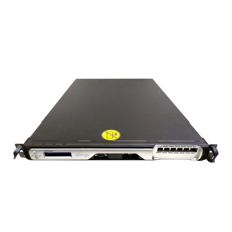
Citrix
Citrix ByteMobile T1010 Quick guide
Citrix
Citrix SD-WAN WANOP 10.2 User manual

Citrix
Citrix ADC MPX 5550 User manual
Popular Network Hardware manuals by other brands
Paradyne
Paradyne MIM-2E1 installation instructions

Crestron
Crestron CNXIRP installation instructions

Matrix Switch Corporation
Matrix Switch Corporation MSC-2HD2424S product manual

gefran
gefran SBI-DCP-33 instruction manual

Panasonic
Panasonic Schottky Barrier Diodes MA3XD21 Specification sheet

Ubiquiti
Ubiquiti mPort-S mPort Serial quick start guide