ECKELMANN LICANBUSAD User manual

LAN Gateway Firmware V1.1c V1.2 03. May 2010
BOARD:DR.-ING. GERD ECKELMANN, CHAIRPERSON – DR. PETER CORDES, DR. FRANK-THOMAS MELLERT
CHAIRPERSOON OF THE SUPERVISORY BOARD: HUBERTUS G. KROSSA REGISTERED: DISTRICT COURT WIESBADEN HRB 12636
eckelmann.de
CAN bus-PC Adapter
Firmware V 1.04
CAN bus-PC Adapter:Order number: LICANBUSAD
Accessory: Y-cable for connecting the PC to the CAN bus
(e.g. for service purposes): Order number: LICANYKAB
Operating instructions

LAN Gateway Firmware V1.1c V1.2 03. May 2010
© 2010 – ECKELMANN AG | BERLINER STRASSE 161 | 65205 WIESBADEN | FON +49(0)611 7103-0 | FAX +49(0)611 7103-133 | eckelmann.de
2/12
ECKELMANN AG
Business Unit Refrigeration and Building Management Systems
Berliner Straße 161
65205 Wiesbaden
Deutschland
Tel.: +49 611 7103-0
Fax: +49 611 7103-133
Homepage: www.eckelmann.de
Information on safety and connection instructions are described in detail in the manual
"Basics and General Safety and Connection Instructions".
All rights to any use whatever, utilisation, further development, forwarding and creation of copies
remain with the ECKELMANN AG company.
In particular, neither the contract partners of ECKELMANN AG nor other users have the right to distribute or
market the IT programs/program parts or modified or edited versions without express written permission. To
some extent, names of products/goods or designations are protected for the respective manufacturer
(registered trademarks etc.); in any case, no guarantee is assumed for their free availability/permission to use
them. The information provided in the description is given independently of any existing patent protection or
other third-party rights.
Before commissioning and use, please check that this is the latest version of the
document.With the publication of a new version of the documentation, all previous
versions lose their validity.
Errors and technical modifications are expressly reserved.

LAN Gateway Firmware V1.1c V1.2 03. May 2010
© 2010 – ECKELMANN AG | BERLINER STRASSE 161 | 65205 WIESBADEN | FON +49(0)611 7103-0 | FAX +49(0)611 7103-133 | eckelmann.de
3/12
1Technical safety information...................................................................................4
2Function of the CAN Bus Adapter...........................................................................5
3Installation and Commissioning of the CAN Bus to PC Adapter.............................5
3.1 Installation of the CAN bus connection..............................................................................................6
3.2 Commissioning...................................................................................................................................8
4Operating states...................................................................................................10
5Technical data......................................................................................................11
5.1 Electrical data CAN bus to PC adapter............................................................................................11
5.2 Electrical date power pack...............................................................................................................11
5.3 Mechanical data CAN bus to PC adapter........................................................................................12

LAN Gateway Firmware V1.1c V1.2 03. May 2010
© 2010 – ECKELMANN AG | BERLINER STRASSE 161 | 65205 WIESBADEN | FON +49(0)611 7103-0 | FAX +49(0)611 7103-133 | eckelmann.de
4/12
1 Technical safety information
1. Commissioning and operation of the device may only be performed by qualified
personnel. "Qualified personnel" as defined by this technical safety information
means persons who have the authorisation to start up, earth and designate devices,
systems and electric circuits in accordance with security technology standards.
2. Mounting, positioning and wiring may only be conducted when the electricity
supply to the assembly has been cut off.
3. The faultless and safe operation of the product presupposes proper transport,
appropriate storage, positioning and assembly, as well as careful operation and
maintenance.
4. Voltage must only be supplied by VDE-tested and CE-certified power packs.
5. Ensure that the voltage supply and the data cable are correctly connected.
6. If the product is brought into the working area from a cold environment,
condensation may form. The product must be completely dry before being
commissioned. Do not assemble or install the product near water or in damp
surroundings.
7. Do not take the product apart or remove the enclosure. The guarantee rights will
become invalid if the housing is opened.
LAN Gateway Firmware V1.1c V1.2 03. May 2010
© 2010 – ECKELMANN AG | BERLINER STRASSE 161 | 65205 WIESBADEN | FON +49(0)611 7103-0 | FAX +49(0)611 7103-133 | eckelmann.de
5/12
2 Function of the CAN Bus Adapter
The CAN bus to PC adapter (article number LICANBUSAD) is designed for use in the E•LDS system. It forms
the interface between a user PC/service PC, on which the LDSWin software is installed, and the CAN bus,
through which communication is established with the E•LDS components.
Typical applications:
•Enables the LDSWin software to communicate with individual E•LDS components
(e.g. CI 3000, VS 3010, VS 300, UA 300) via the CAN bus
•Communication with E•LDS components at any connection point on the CAN bus
•In the case of serial connection to LDSWin prevents the distance between PC and
CI 3000 / CI 3100 / CI 300 being restricted to 15 m
•Enables LDSWin connection to CI 3000 / CI 3100 / CI 300 store computer
when COM port is occupied by modem
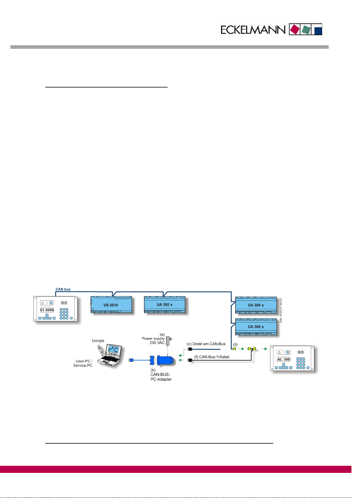
Integration in the E•LDS system:
The CAN bus connection is based on the CiA standard. The CAN bus PC adapter (b) must be provided with
power by an external power pack (e, provided). The CAN bus to PC adapter is connected to the PC serial port
(COM port) by means of a special adapter cable (a, provided).
Connection to the CAN bus:
A) The connection to the COMBICON plug on the CAN bus (d) is directly established via the 9-pole Sub-Min-D
plug with screw terminals (c, provided) (see also chapter 3.1).
B) To any required E•LDS component. Here all that is required is for its COMBICON plug connection to the
CAN bus to be interrupted and the CAN bus Y-cable (f, article number LICANYKAB) to be inserted in
between (also ideal for service purposes)
Picture 2-1: CAN bus to PC adapter in E•LDS system
Interfaces:
CAN bus: Communication in E•LDS system
RS232: Serial interface (COM port) of the PC
3 Installation and Commissioning of the CAN Bus to PC Adapter

LAN Gateway Firmware V1.1c V1.2 03. May 2010
© 2010 – ECKELMANN AG | BERLINER STRASSE 161 | 65205 WIESBADEN | FON +49(0)611 7103-0 | FAX +49(0)611 7103-133 | eckelmann.de
6/12
3.1 Installation of the CAN bus connection
Before the CAN bus to PC adapter is put into operation, the 9-pole Sub-Min-D-Plug and the COMBICON plug
must be connected using a CAN bus cable. The COMBICON plug can then be connected to the CAN bus
interface of an E•LDS component (e.g. AL 300, CI 3000). Special details for the connection to the CAN bus
(specification of conductor type, permissible conductor length, necessary terminating resistor and correct
routing) are described in detail in the chapter Introduction.
The following 3 steps are required:
1. Connect the CAN bus cable to the Sub-Min-D plug (see table 3.1-1 and picture 3.1-1)..
CAN bus Wire/
colour 9-pole Sub-
Min-D COMBICON
plug Comments
SHLD SHLD - 1
SHLD is ONLY to be connected to the pull relief on the 9-
pole Sub-Min-D plug housing
(see picture 3.1-1)
CAN-GND Green Pin 3 2 -
CAN-Low Brown Pin 2 3
CAN-High White Pin 7 4
If the adapter is at the end of the CAN bus line, a
terminating resistor must be inserted between pin 2 and
pin 7: R = 100 Ohm / 0.25 W (see picture 3.1-1)
Table 3.1-1: Wire assignment for Sub-Min-D and COMBICON plugs
21345
7
689
CAN-Low CAN-GND
CAN-High
ZNR. 51203 57 830 D0
R = 100 Ohm
23
7
Picture 3.1-1: Wire assignment Sub-Min-D plug (with terminating resistor R = 100 Ohm / 0.25 W).
2. Assembly according to the accompanying Sub-Min-D plug instructions.

LAN Gateway Firmware V1.1c V1.2 03. May 2010
© 2010 – ECKELMANN AG | BERLINER STRASSE 161 | 65205 WIESBADEN | FON +49(0)611 7103-0 | FAX +49(0)611 7103-133 | eckelmann.de
7/12
3. Connect the CAN bus cable to the COMBICON plug (see table 3.1-1 / picture 3.1-2).
Picture 3.1-2: Wire assignment for the connection of the COMBICON plug to the CAN bus (pictured without
through looping)
For safe operation it is sufficient to connect the signals CAN-low, CAN-high and
CAN-GND to the Sub-Min-D plug.
The additional use of the CAN-SHLD in the Sub-Min-D plug can cause problems as
the E•LDS system’s CAN bus uses CAN-SHLD and CAN-GND differently, although
these signals are connected internally within the adapter!
Incorrect shielding can lead to electromagnetic noise fields. During wiring work, it is
essential that the conductors be connected by a professional and correctly shielded.
If the CAN bus to PC adapter is not positioned at the end of the CAN bus, then the
cable must be looped through from the Sub-Min-D plug.
The terminating resistor in picture 3.1-1 is obsolete and is to be attached to the end
of the CAN bus (on the last node).

LAN Gateway Firmware V1.1c V1.2 03. May 2010
© 2010 – ECKELMANN AG | BERLINER STRASSE 161 | 65205 WIESBADEN | FON +49(0)611 7103-0 | FAX +49(0)611 7103-133 | eckelmann.de
8/12
3.2 Commissioning
Picture 3.2-1: CAN Bus to PC Adapter
The commissioning of the CAN bus to PC adapter consists of the following 8 steps:
1. Turn off the PC.
2. Connect the RS232 plug (a) of the adapter (b) with the PC’s serial interface (COM port).
3. Attach the Sub-Min-D plug (c) to the adapter (b) and screw into place.
4. Connect the COMBICON plug (d) with the CAN bus and plug into E•LDS components.
(See chapter 3.1 – Installation CAN Bus Connection).
5. Connect the power pack (e) to the adapter (b) and plug into the mains power supply.

LAN Gateway Firmware V1.1c V1.2 03. May 2010
© 2010 – ECKELMANN AG | BERLINER STRASSE 161 | 65205 WIESBADEN | FON +49(0)611 7103-0 | FAX +49(0)611 7103-133 | eckelmann.de
9/12
6. Turn on the PC and start the LDSWin software.
7. Under the menu item “File /Settings” in the “General” screen select the required COM port and “CAN bus
adapter” (see picture 3.2-2) and press “Accept”.
Picture 3.2-2: CAN Bus to PC Adapter
8. Communication can now be established with the E•LDS components via the LDSWin software.
For further information see the LDSWin Software documentation.
If communication is only carried out with individual components without a store
computer CI 3000 / CI 3100 /CI 300 being connected to the CAN bus, then “SC not
available” must also be selected.
LAN Gateway Firmware V1.1c V1.2 03. May 2010
© 2010 – ECKELMANN AG | BERLINER STRASSE 161 | 65205 WIESBADEN | FON +49(0)611 7103-0 | FAX +49(0)611 7103-133 | eckelmann.de
10/12
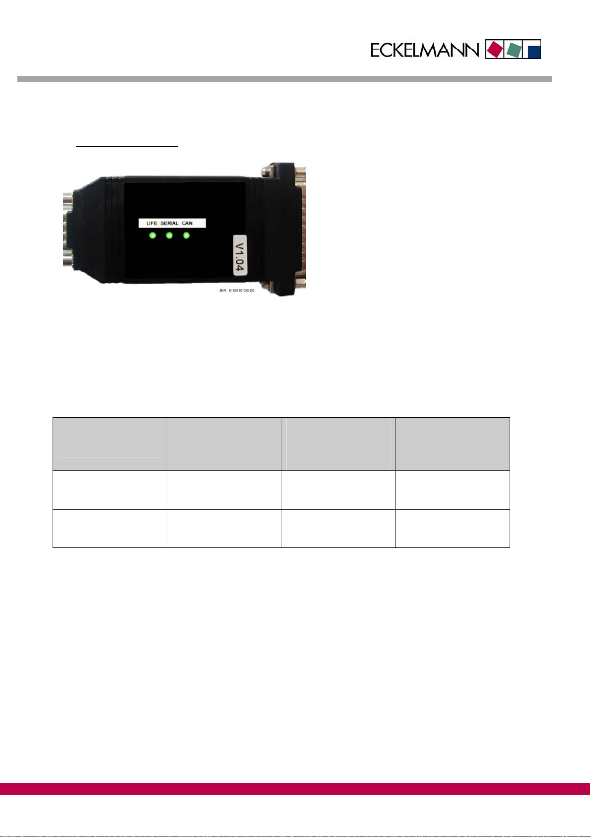
4 Operating states
Picture 4-1: CAN bus to PC adapter status LEDs
During operation the CAN bus to PC adapter’s “LIFE“ LED is lit green. During data transmission, i.e.
communication between the CAN bus and the PC’s serial interface the LEDs “CAN” and “SERIAL” flash green
on a cyclical basis. If the “CAN” or “SERIAL” LEDs are lit red then there is a fault in the interfaces.
Colour LED 1
LIFE
LED 2
SERIAL
LED 3
CAN
Green - flashing Operating Data transfer
serial Data transfer
CAN bus
Red -lit - Fault
serial interface Fault
CAN bus interface

LAN Gateway Firmware V1.1c V1.2 03. May 2010
© 2010 – ECKELMANN AG | BERLINER STRASSE 161 | 65205 WIESBADEN | FON +49(0)611 7103-0 | FAX +49(0)611 7103-133 | eckelmann.de
11/12
5 Technical data
5.1 Electrical data CAN bus to PC adapter
Technical data CAN Bus to PC Adapter
Article numbers CAN Bus to PC Adapter: LICANBUSAD
CAN bus Y-cable: LICANYKAB
Physical interface CAN compliant with ISO 11 898
Temperature range 0° C .. +55° C
CAN bus connection 9-pole Sub-Min-D plug
CAN compliant with CiA / DS102
PC connection 9-pole Sub-Min-D plug on connection cable
Housing Plastic, degree of protection IP30
Indicator 3 x Duo LEDs (green/red)
Power supply External, 7 - 32 V DC per jack plug
Current consumption typically 500 mA at 8 V DC
CE conformity Manufacturer’s CE declaration of conformity
5.2 Electrical date power pack
Technical data Power pack
Input voltage 90 - 260 V AC
Output voltage 12 V DC stabilised +/- 3 %
Max. output current 500 mA
Temperature range 0° C ... +40° C
Plug (AC side) Euro plug
Plug (DC side) Standard jack plug type DC 3.5/1.3mm
External diameter: 3.1 mm
Internal diameter: 1.3 mm
Length: min. 9 mm
Connector assignment / dimensions
jack plug
3,5 mm
min. 9,0 mm
-+
1,3 mm
ZNR. 51203 57 530

LAN Gateway Firmware V1.1c V1.2 03. May 2010
© 2010 – ECKELMANN AG | BERLINER STRASSE 161 | 65205 WIESBADEN | FON +49(0)611 7103-0 | FAX +49(0)611 7103-133 | eckelmann.de
12/12
5.3 Mechanical data CAN bus to PC adapter
102 mm
LIFE SERIAL CAN
54,0 mm
95,5 mm
ZNR. 51203 57 630
41,0 mm
The right to make technical changes is reserved! No liability is accepted for any errors!
This manual suits for next models
1
Table of contents


