ECKELMANN E-Control CNC Operator's manual

PRODUCT DOCUMENTATION
eckelmann.de
ECKELMANN AG, WIESBADEN • eckelmann.de • FERROCONTROL GMBH & CO. KG, HERFORD
E-Control
CNC
Introduction Manual ENC66

Eckelmann AG
Berliner Straße 161
65205 Wiesbaden
Fon +49 (0) 611 / 7103 - 0
Fax +49 (0) 611 / 7103 - 133
E-Mail [email protected]
Internet http://www.eckelmann.de

3 / 97
Introduction Manual ENC66
eckelmann.de
E-Control
CNC
Introduction Manual ENC66
E-Control CNC Introduction Manual ENC66
English
2nd edition : März 2011
Target group:
Technicians and all trained personnel familiar with the fundamental function of automa-
tion systems.
Content of this document:
Additionally to the CNC task the E·Control ENC66 controller can run a PLC program.
The manual is designed to generate a simple CNC program with the Eckelmann controller
E•ENC where particular previous knowledge of CNC programming is not required.
The manual supports you in creating your first CNC program and initiates you in the usage
of the PLC function as per IEC 61131-3 in connection with the CNC core.
Additionally the configuration of the controllers is explained for an effective commission-
ing.
Copyright protection:
All rights to any use whatever, utilisation, further development, forwarding and creation
of copies remain with the ECKELMANN AG company.
In particular, neither the contract partners of ECKELMANN AG nor other users have the
right to distribute or market the IT programs/program parts or modified or edited versions
without express written permission.
To some extent, names of products/goods or designations are protected for the respective
manufacturer (registered trademarks etc.); in any case, no guarantee is assumed for their
free availability/permission to use them.
The information provided in the description is given independently of any existing patent
protection or other third-party rights.
Errors and technical modifications are expressly reserved.
Release: Thomas Franzmann
Name in block letters
29.03.2011
Date
signed. Franzmann
Signature

4 / 97
Revision notification
Tabelle 1:
Tabelle 2:
Tabelle 3:
Version Chapter Date edited by Amendment
1 All 23.09.2010 Martin Kellner First release based on the introduc-
tion manual of the ENC55
21.4.6.229.03.2011 Martin Kellner- E108 and F703 added
- Data blocks corrected for diagnostic
address of the LBM modules

5 / 97
Introduction Manual ENC66
eckelmann.de
Table of Contents
1 Overview.............................................................................. 12
1.1 List of documents................................................................................................. 12
1.2 Controller family E-CONTROL CNC ..................................................................... 13
1.3 Variants „Stand-Alone“ and „With PC-HMI“..................................................... 14
1.4 Status information of the ExC66......................................................................... 15
1.4.1 Status information during booting .................................................................... 15
1.4.2 LEDs while booting .............................................................................................. 16
1.4.3 Status information during start of firmware ..................................................... 17
1.4.4 Status information in normal operation ............................................................ 18
1.4.5 The LEDs in normal operation............................................................................. 19
1.4.6 Error indication .................................................................................................... 20
1.4.6.1 Error indication during booting.......................................................................... 20
1.4.6.2 Error indication in normal operation ................................................................. 20
2 Connection and installation............................................... 22
2.1 Example of a structure......................................................................................... 22
2.2 Controller connection.......................................................................................... 22
2.3 Serial connection.................................................................................................. 24
2.4 Connection via Ethernet...................................................................................... 24
2.4.1 Connection via Ethernet (local connection) ....................................................... 25
2.4.2 Connection via Ethernet (network) .................................................................... 25
3 Monitor interface of the controller................................... 26
3.1 Running the terminal program........................................................................... 26
3.1.1 Configuration of the terminal program............................................................. 26
3.2 Calling of the monitor interface......................................................................... 28
3.3 Configuration of an Ethernet connection.......................................................... 30
3.4 Important monitor commands............................................................................ 32
3.5 Possible errors ...................................................................................................... 33
4 Setting of the IP address in the controller........................ 34
4.1 Setting of the IP address via the monitor interface (serial interface) .............. 34
4.2 Setting of the IP address via Ethernet (network or local) with NetConf.......... 35
4.2.1 Automatically display controllers in NetConf .................................................... 35
4.2.2 Change the IP address of a controller with NetConf......................................... 36
4.2.3 Configure gateway and subnet mask in NetConf.............................................. 37
4.2.4 Add a controller in NetConf manually ............................................................... 37

6 / 97
4.2.5 MAC address ........................................................................................................ 38
5 Update of the firmware via the boot monitor.................. 39
5.1 Access to the boot monitor................................................................................. 39
5.2 Check of the firmware version............................................................................ 40
5.2.1 Variant „with PC-HMI“........................................................................................ 40
5.2.2 Variant „Stand-Alone“ ........................................................................................ 40
5.3 Update of the firmware ...................................................................................... 40
5.4 Remove a firmware ............................................................................................. 42
5.5 Commands of the boot monitor......................................................................... 43
6 Parameterizing of the drives .............................................. 44
6.1 Parameterizing of the drives in detail................................................................ 44
6.2 Number of axes and CAN node addresses ......................................................... 44
6.3 Important machine constants ............................................................................. 45
6.4 Machine constants file......................................................................................... 48
6.5 Loading of a file with machine constants into the controller .......................... 49
6.6 Synchronized and gantry axes ............................................................................ 50
6.6.1 Example of synchronized axes at the CAN-Bus .................................................. 50
6.6.2 Example of synchronized axes with analog interface ....................................... 52
6.6.3 Example of a gantry axis with CAN-Bus ............................................................. 53
7 CNC programming as per DIN 66025.................................. 54
7.1 G-functions........................................................................................................... 54
7.2 M-functions .......................................................................................................... 56
8 StdHMI .................................................................................. 57
8.1 Installation StdHMI .............................................................................................. 57
8.2 Starting the StdHMI............................................................................................. 57
8.3 Modifying machine constants............................................................................. 58
8.4 Checking the drives ............................................................................................. 59
8.5 Individual manual checking of drives in jogging mode .................................... 60
8.6 Programming as per DIN 66025 .......................................................................... 60
8.6.1 The program editor ............................................................................................. 61
8.6.2 Editing the program ............................................................................................ 62
8.6.3 Saving the DIN program...................................................................................... 63
8.6.4 Loading a program into the controller .............................................................. 63
8.6.5 Starting of the program in the controller .......................................................... 64

7 / 97
Introduction Manual ENC66
eckelmann.de
8.6.6 Extending of the program for the lowering of the tool ................................... 65
8.7 Exiting of the program StdHMI........................................................................... 68
8.8 Changing the user language of the program StdHMI....................................... 68
8.9 Changing the colour setting of the graphical display ....................................... 68
9 Generating of a PLC program with ETOOLS PLC2 ............. 70
9.1 Programming – Software ETOOLS PLC/2 ............................................................ 70
9.2 Installation ETOOLS PLC/2 (CoDeSys) .................................................................. 70
9.3 Hardware.............................................................................................................. 70
9.4 Configuration of a controller in ETOOLS PLC/2 ................................................. 71
9.4.1 Calling of the program E-Tools PLC/2 ................................................................. 72
9.4.2 General instructions for the address mapping of IO modules .......................... 73
9.4.2.1 Limitations of FBM modules................................................................................ 73
9.4.2.2 General instructions for the PLC configuration with LBM modules ................. 73
9.4.3 PLC configuration ................................................................................................ 74
9.4.3.1 Add and configure LBM modules ....................................................................... 75
9.5 Task configuration ............................................................................................... 77
9.6 Changing of the language german / english ..................................................... 77
10 Sample PLC program........................................................... 79
10.1 Sample program CNC Test................................................................................... 79
10.2 Required libraries................................................................................................. 79
10.3 System variable and data block .......................................................................... 79
10.4 Task for the M-functions M14 and M15 ............................................................. 80
10.5 Calling of the program ........................................................................................ 81
10.6 Sequential function cart ...................................................................................... 81
10.7 Definition of inputs and outputs ........................................................................ 82
10.8 Function START_STOP.......................................................................................... 83
10.9 Function RELEASE_SIGNAL_HANDLER ................................................................ 83
10.10 Function M_FUNCTIONS ...................................................................................... 83
10.11 Loading of the program into the controller ...................................................... 85
10.11.1 Serial connection.................................................................................................. 85
10.11.2 Network connection ............................................................................................ 86
10.11.3 Loading of the program ...................................................................................... 87
10.11.4 Starting of the program in the controller.......................................................... 88
10.11.5 Stopping of the program in the controller ........................................................ 88
10.11.6 Reset of the data memory in the controller....................................................... 88
10.11.7 Permanent storage of the program in the controller (boot-project) ............... 88
10.11.8 Termination of communication with the controller.......................................... 89

8 / 97
11 Testing of the CNC and PLC program ................................. 90
11.1 Connection of the controller inputs ................................................................... 90
11.2 Loading and starting the PLC program .............................................................. 90
11.3 Loading and starting of the CNC program ........................................................ 90
11.4 Error messages of the CNC program .................................................................. 91
9 / 97
Introduction Manual ENC66
eckelmann.de
Conventions
General notes
A general note is composed of three parts:
1. The letter „i“
2. A blue bar with the word „Note“
3. The text of the note below the bar
Example:
x
Note
Please observe that the extended interface generates a bus load, which is higher by approx.
50 %.

10 / 97
Explanations regarding the safety instructions
Safety instructions and hazard warnings are composed of five parts:
1. An icon at the margin
2. A bar with the signal word, the colour of which depends on the danger level.
3. A short, clear description of the danger
4. A description of possible consequences
5. A list of measures for danger prevention
Example:
x
DANGER
High voltage in power supply unit
Severe injuries or death due to electric shock
• Pull off mains plug prior to open the housing
• Do not put objects in the venting slots during operation
The danger levels are described in the following table:
Tabelle 1:
Table 1: Warning levels
Marking bar Warning level
Severe consequential damage such as death or irreversible
injuries
Imminent hazardous situation if the precautions are not observed.
Severe consequential damage such as death or irreversible
injuries
Potentially hazardous situation if the precautions are not observed.
Slight injuries (reversible)
Potentially hazardous situation if the precautions are not observed.
Property damage
Devices may be damaged if the precautions are not observed.
DANGER
WARNING
CAUTION
NOTICE

11 / 97
Introduction Manual ENC66
eckelmann.de
Warning signs
Tab el le 2 :
Table 2: Warning signs
Pictograph Warning Possible consequences
Warning of general
danger
Nonobservance of the warning may cause property
damage and/or personal injuries (in extreme cases,
most severe injuries or death).
Warning of dangerous
electric voltage
Nonobservance of the warning may cause death or
most severe injuries.
Warning of hot surfaces Nonobservance of the warning may cause burning
of the skin.
Warning of contusions Nonobservance of the warning may cause contu-
sions or bone fractures.
Warning of damage to
the electronics
Nonobservance of the warning may destroy elec-
tronic components in the system due to ESD (elec-
trostatic discharge), overload or wrong connection.
Warning of mechanical
damage to the machine
Nonobservance of the warning may damage or
even destroy machine parts.
12 / 97
1Overview
1.1 List of documents
The manual makes reference to other documents that include the respective details.
Tabelle 3:
Table 3: List of documents
Manual
/1/ User manual PLC/2 for CNC
/2/ Installation manual Standard HMI
/3/ User manual Standard HMI
/4/ Communication protocols
/5/ different technical manuals for FBM modules Diverse
/6/ ECNC configuration manual
/7/ ECNC programming instruction manual
/8/ ECNC configurations instructions
(interface PLC<->NCR)
/9/ Technical manual for LBM modules
This document also makes reference to the following technical descriptions of the control-
lers.
Tabelle 4:
Table 4: List of technical descriptions
Manual
/A/ ExC66 Technical Description
/B/ ExC55 Technical Description
/C/ PNC55 Technical Description
/D/ CNC55 Technical Description
13 / 97
Introduction Manual ENC66
eckelmann.de
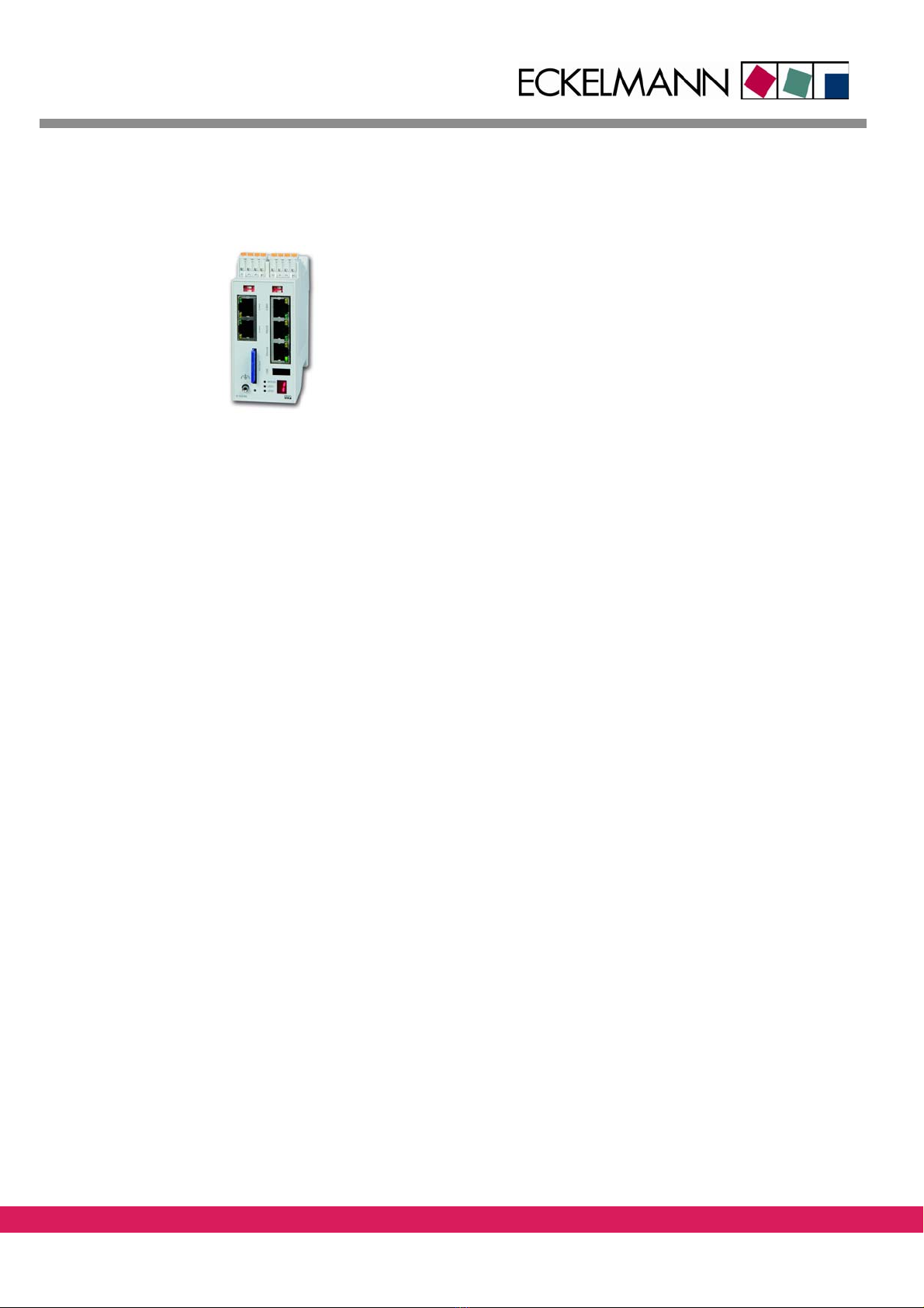
1.2 Controller family ECONTROL CNC
Abbildung 1:
The controller family E-Control CNC comprises the ENC66, ENC55,
PNC55 and CNC55 controllers.
This manual describes the ENC66 controller, that is designed for top
hat rail mounting.
The memory size and the number of interfaces depends on the or-
dered configuration.
The configuration code is an extension of the order number and is
part of the type label. The type label is on the bottom side of the
ENC66.
Figure 1: ENC66
The controller has the following features:
• Numerical controller (CNC) for 2 to 16 axes (depending on the ordered configura-
tion)
• CNC programming as per DIN 66025
• Integrated PLC function, programming as per IEC 61131-3
• 2 to 4 CAN busses (depending on the ordered configuration)
• Usage of local bus modules (LBM) for inputs and outputs and for analog CNC axes
• Connection of field bus modules for inputs and outputs
• Memory extension via SD card slot and USB
You can find more details in /A/.

14 / 97
1.3 Variants „Stand-Alone“ and „With PC-HMI“
On principle, the controllers can be operated in 2 different operating modes:
• The variant „Stand-Alone“ starts with the firmware immediately after the application of
the voltage
• The variant „With PC-HMI“ waits after the application of the voltage for the loading of a
firmware from a PC via the program StdHMI
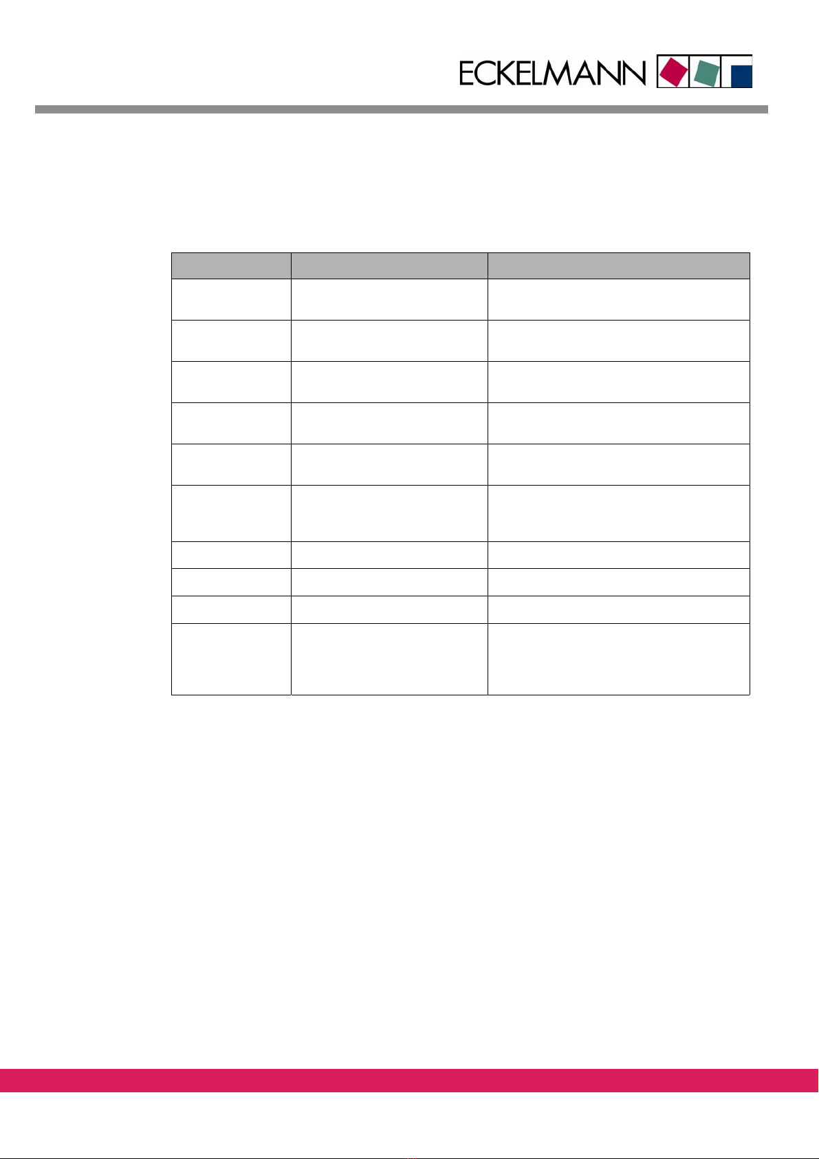
The variant „With PC-HMI“ is the standard variant that is supplied. The table shows the two
variants in comparison:
Tabelle 5:
Table 5: Operating modes PC-HMI and Standalone in comparison, ENC66
With PC-HMI Stand-Alone
Use The controller operates a
machine by means of coupling
with a PC with graphical user
interface, the PC is used for the
loading of programs and for the
operation of the controller
The controller operates a
machine without
further coupling with a PC
Firmware installed on
the controller
Bootloader Bootloader
NC-Firmware
Installation of the
firmware
No additional software is neces-
sary. The NC firmware is loaded
from the PC after the starting of
the StdHMI by means of the
bootloader.
The NC firmware is installed by
the bootloader into the control-
ler FPROM memory
Behaviour of the con-
troller after the appli-
cation of the voltage
Upon application of the voltage,
the controller waits for the load-
ing of the NC firmware via the PC
Upon application of the voltage,
the controller starts automati-
cally the bootloader and then
the NC firmware
7-segment indicator
after application of
the voltage
Two adjacent segments rotate in
clockwise direction
The 7-segment display works as
described in chapter 1.4
Starting of the NC
firmware
The NC firmware is available on
the PC and is loaded after the
starting of the graphical user
interface StdHMI from the PC
into the controller RAM by
means of the bootloader and is
started
The NC firmware is loaded from
the FPROM memory into the
RAM by means of the boot-
loader. Then the NC firmware is
executed in the RAM.
7-Segment indicator
after starting the NC
firmware
Each segments of the 7-segment indicator are assigned to a system
task. The brightness of the various segments corresponds to the com-
puting load of the single tasks in the system.

15 / 97
Introduction Manual ENC66
eckelmann.de
The following files are reserved for the firmware of the controllers:
Tab el le 6 :
Table 6: Firmware files
File Description Installation via bootloader
BOOT66.BIN Bootloader for installing the NC
firmware. It has netboot functionality to
reload the firmware via the StdHMI
ENC66.RSC NC firmware for the ENC66 x
Other filenames with the extension „.rsc“ and the name „boot*.bin“ must not be used.
1.4 Status information of the ExC66
Besides 3 status LED, a 7-segment indicator is available on the assembly which indicates the
current operating state and probable faults of the assembly, depending on the operating
state.
In current operation, the 7-segment indicator is used as status information. In case of a soft-
ware error, the occurring error is indicated in the form of a defined string of characters.
The green LED indicates the watchdog function and is lit if no malfunction occurs. The two
other LED are used to indicate the CAN1 state. In case of the 7-segment indication a distinc-
tion is made between booting and operation.
1.4.1 Status information during booting
At the beginning of booting, a memory test is made and the firmware is loaded. In this
phase, the following indications are made.
Tab el le 7 :
Table 7: 7-segment indicator, Status information during booting
7-segment indicator Meaning
0Hardware initialization
1RAM test
2Initialization terminated
3Loading of firmware from FROM to RAM
4Firmware loaded
5Firmware started

16 / 97
1.4.2 LEDs while booting
The single LED on the front panel indicate the following state and meaning during boot-
ing.
Tabelle 8:
Table 8: LEDs while booting, ENC66
LED Indication Meaning
WDOG Off Watchdog is not triggered in bootloader
CAN1/LED1 Off Not used
CAN1/LED2 Off Not used
CAN2/yellow Off Not used
CAN2/green Off Not used
RS232/green Off or flashing light RS232/TX state (indicates transmitting of data)
RS232/green Off or flashing light RS232/RX state (indicates receiving of data)
ETHERNET/yellow Flashing light Ethernet/ activity status
ETHERNET/green Off or on Ethernet/ connect status
CAN3/green Off Not used
CAN3/green Off Not used
CAN4/green Off Not used
CAN4/green Off Not used
17 / 97
Introduction Manual ENC66
eckelmann.de
1.4.3 Status information during start of firmware
The firmware is started after booting. The following indications are made in this phase.
Tab el le 9 :
Table 9: 7-segment indicator, Status information during start of the firmware, ENC66
7-segment indicator Meaning
0Initialization of processor
1Initialization of software
2Initialization of operating software
3Initialization of task and mailbox
4Initialization of I2C hardware
5Initialization of file system
6Initialization of local bus
7Hardware check
Flashing light of segment Normal state acc. to description in /A/
Continuous error number Error state acc. to tables in chapter 1.4.6.1
18 / 97
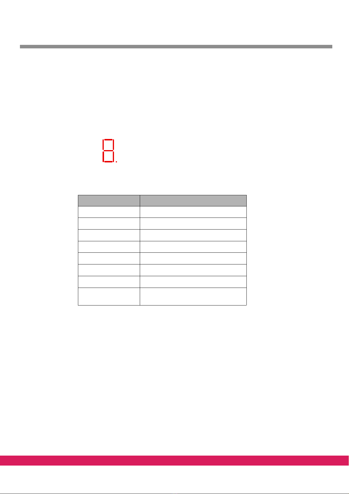
1.4.4 Status information in normal operation
After the start of the firmware, the controller changes to normal operation.
The single segments of the 7-segment indicator are assigned to a system task each. The
brightness of the various segments corresponds to the computing load of the single tasks
in the system.
The assignment is as follows:
Abbildung 2:
a
b
c
d
e
fg
h
Figure 2: 7-Segment indicator
Tabelle 10:
Table 10: Status information in normal operation, ENC66
Segment Meaning
aPLC (PLC program)
bSRV (Services)
cAXE (fine interpolator)
dZST (central controller)
eINT (interpreter)
fPOS (interpolator)
gNET (Ethernet communication)
h (dot) Pulses in the rhythm of interpolator
(freq=1/MK_DELTAT [Hz])
19 / 97
Introduction Manual ENC66
eckelmann.de
1.4.5 The LEDs in normal operation
The state of the single LED in normal operation is described in the respective chapters of /
A/. The following table gives an overview:
Tab el le 1 1: .
Table 11: LEDs in normal operation, ENC66
LED Indication Meaning
WDOG On:
Off:
Watchdog ok
Error: Watchdog is de-energized
CAN1/LED1 Flashing light:
Flashing at 2 Hz:
RX-Status ok
RX-Error-Counter>13
CAN1/LED2 Flashing light:
Flashing at 2 Hz:
TX-Status ok
TX-Error-Counter>13
CAN2 to CAN4
yellow
Flashing light:
Flashing at 2 Hz:
TX-Status ok
TX-Error-Counter>13
CAN2 to CAN4
green
Flashing light:
Flashing at 2 Hz:
RX-Status ok
RX-Error-Counter>13
CAN2 to CAN4
green and yellow
synchronous
Synchronous flashing at 1 Hz:
Synchronous flashing at 0,5 Hz
State error passive
State bus-off
RS232/yellow Flashing light: Transmitting of data (TX-Status)
RS232/green Flashing light: Receiving of data (RX-Status)
ETHERNET/yellow Flashing light: signals data transfer via RX or TX
ETHERNET/green Off:
On:
no ethernet connection available
as soon as an ethernet connection is estab-
lished (result of the internal link integrity
test)

20 / 97
1.4.6 Error indication
1.4.6.1 Error indication during booting
Probable errors in the booting phase are signalled by the following indication pattern. The
indication shows the pattern sequentially with 2 characters/sec. The indication is made until
the controller is reset (exception: start of the boot monitor).
Tabelle 12:
Table 12: Error indication during booting, ENC66
7-segment indicator Meaning Start of boot
monitors
E01 RAM error
E02 Checksum error in boot loader (FPROM)
E05 unknown FPROM type
E06 Error during loading of firmware from FPROM x
E07 Error during start of firmware x
E88 Processor exception
A running light in the 7-segment indicator (two adjacent segments rotating in clockwise di-
rection) shows that the boot monitor is active.
The boot monitor is activated either by the user or by the boot loader, if the start of the
operating system has not been made successfully after E06 and E07.
1.4.6.2 Error indication in normal operation
Probable errors are signalled by the following indication pattern. The indication shows the
pattern sequentially with 2 characters/sec. The indication is made until the controller is re-
set.
Tabelle 13:
7-segment
indicator
Meaning
E104 ZST / I2C initialization failed
E105 ZST / EEPROM initialization failed
E106 ZST / RTC initialization failed
E107 UTI / Power failure of real-time clock, time invalid
E108 ZST / Identification of the ExC66-expansion card failed
F001 SYS / Incorrect segment at freemem()
F002 SYS / Invalid segment at freemem
F003 SYS / Invalid argument at PutMsg()
F004 SYS / Unexpected termination of a task
Table 13: Error indication in normal operation, ENC66
Table of contents


