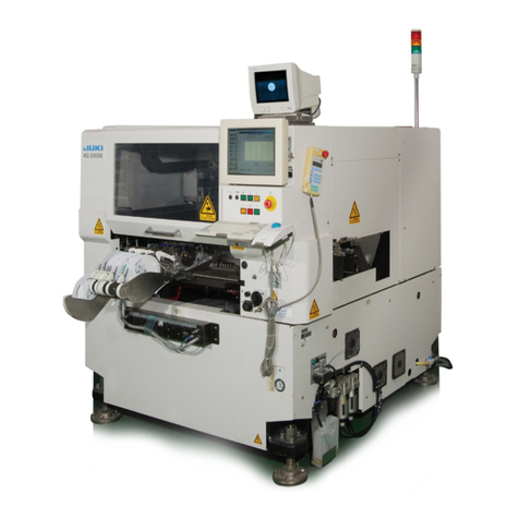
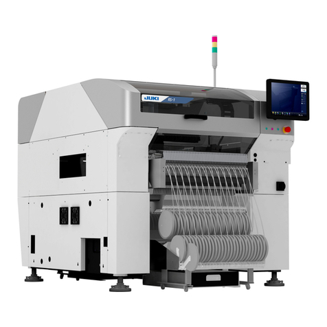
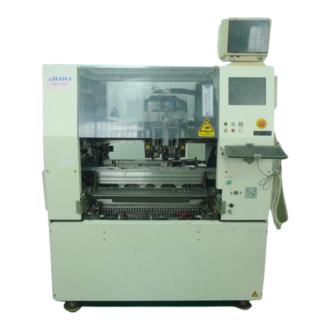
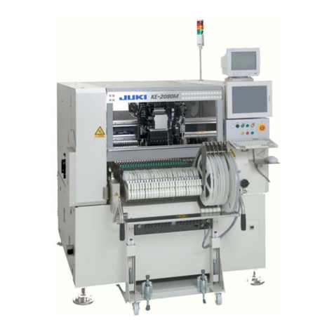
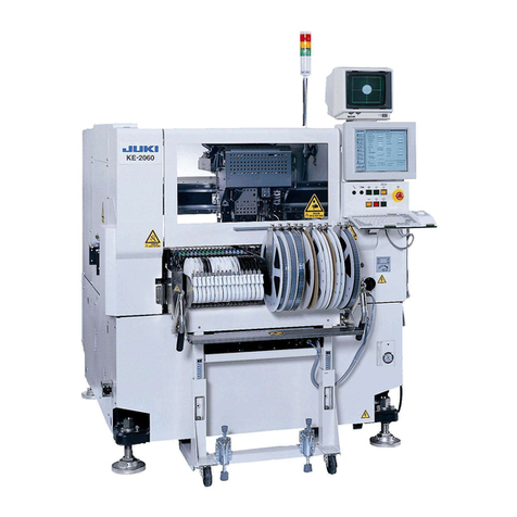
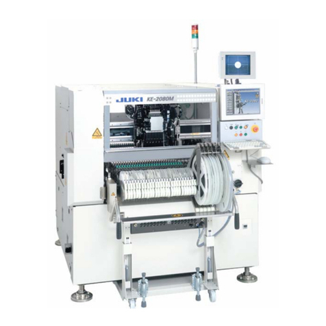
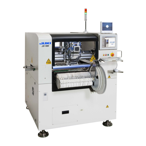
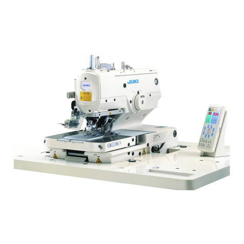
JUKI KE-2070 User manual

40052401
High-Speed Chip Shooter
KE-2070
High-Speed Flexible Mounter
KE-2080/2080R
OPERATION MANUALⅠ
(For Operators)
Thank you for purchasing a product of our company.
CAUTION In order to ensure safe use of KE-2070/ 2080/ 2080R, be sure to read
this Manual before using the machine.
After reading this Manual, keep it at a fixed location so that it will be
available at any time.

Important
(1) No part of this document may be copied or reproduced without the prior
permission of JUKI Corporation. (Including software and program)
(2) The contents of this document are subject to change without notice.
(3) This manual is prepared with extreme care. However, if you have any question
or find any error or omission in writing, contact our dealer or JUKI Corporation.
(4) JUKI Corporation shall disclaim all the responsibility for any trouble resulting
from the user's abnormal operation regardless of Item (3).
(5) Microsoft, Windows are registered trademarks or trademarks of Microsoft
Corporation in the United States and /or other countries.
The company names and product names mentioned in this document are
generally registered trademarks or trademarks of the respective companies.

i
CAUTION For the safe operation of machinery
All personnel engaged in the operation of the chip placer and its accessories (here after referred to as
"machines") including the operators, service and maintenance personnel are required to read through this safety
warning to make familiar with its handling to prevent accidents and injuries.
This "Warning: For the safe operation of machinery" instructions contain aspects that are not included in the
instruction sheet attached to the product.
The following symbols are used throughout this instructions and on the product for the better understanding of
various warning labels. Please make yourself familiar with the contents and act accordingly.
1) Danger levels
DANGER
Parts of machinery the negligence or mishandling of which committed during the
operation, maintenance or other services on such parts will lead to severe accidents
involving serious personal injuries or even death.
WARNING
Parts of machinery the negligence or mishandling of which committed, or are left
unattended, during the operation, maintenance or other services on such parts may
cause potential danger to the personnel which may lead to injuries and/or even death.
CAUTION
Parts of machinery the negligence or mishandling of which committed, or are left
unattended, during the operation, maintenance or other services on such parts may
cause the medium-to-light level of hazards to the personnel involved.
2) Warning, prohibition and directive marks
Warning, prohibition and directives are marked with the following symbols:
Warning marks
Your hands or clothes
may get caught by the
machines.
Beware of moving parts.
Contacts with them may
cause injuries.
Beware of movable parts.
Contacts with them may
cause injuries.
High voltage!!
Beware of electric
shocks.
Beware of hot parts.
Contacts with them may
cause a burn.
If any load is imposed or you
lay your hand on the
machine, it may be
damaged.
Directive symbols
It symbolizes a contact to a grounding wire. It indicates the direction of turn.
Matters of Caution Regarding Safety
To prevent accidents due to electric shock, turn off power supply if it is necessary to open the electrical
equipment box. For added precaution, open the lid of the box only after a lapse of more than five minutes.
To turn off power supply means to turn off a power supply switch and then to
draw out a power plug from a receptacle or to separate the power cable from
the supply side. Hereinafter the same.
Situations in Which It Is Necessary to Turn Off Power Supply
1. In the case of an abnormality or an accident, or in the event of power failure,
immediately turn off power supply.
2. In order to prevent accidents due to unintended start-up of the machine, carry out inspection, repair, or
cleaning of the machine only after turning off power supply.
3. When drawing out the power supply plug, do it by holding the plug itself, not the cord.
DANGER

ii
Basic Matters of Precaution
1. Be sure to read all documents included in this Manual and the attached booklet before using this
machine. Also, keep this Manual carefully so as to be able to read it whenever necessary.
2. Contents of this Manual include items that are not included in specifications of the machine purchased.
3. The machine should be operated only by the operator who has learned how to run it.
4. Regarding the repair or maintenance (excluding daily inspection and other matters specified in the
Manual), ask our company or its agent to do it.
5. General maintenance, inspection, and repair (matters specified in this Manual) shall be conducted only
by specialized maintenance engineers who have finished the maintenance course specified by our
company.
With regard to repair (matters specified in this Manual), use genuine parts of our company.
Safety Equipment, Alarm Label
1. In order to prevent accidents due to nonpresence of safety equipment, start to
operate this machine only after confirming that the equipment is suitably installed at the specified
position.
2. If the safety equipment is dismantled, be sure to attach it to its original position, and confirm that it
operates normally.
3. Make sure that the warning label stuck to the machine will be always clearly visible.
If it has been peeled off or stained, order new labels from our company and exchange old labels with
new ones.
4. If the safety equipment is damaged, remove it. Never operate the machine. If you operate the
machine without the safety equipment, it may lead to severe accidents involving serious personal
injuries or even death.
<Where to stick warning labels>
Front Rear
Application
1. Never use this machine for purposes other than its original application.
Our company will not be responsible in the case of its use for other application.
2. Do not remodel this machine. Our company will not be responsible for any accident arising as a
result of its remodeling.
Operational Training
1. To prevent accidents due to unaccustomed handling, operation of this machine must be limited to
operators who have participated in the operation training specified by our company and have
appropriate knowledge and operating skills.
Moving parts
warning label
Moving parts
warning label
"Take care not to be
caught in the machine
warning label
High voltage
warning labels
Safety cover
CAUTION

iii
Matters of Caution at Each of Its Use Stages
Transport
1. When lifting the machine or moving it, take sufficient safety measures so that no dropping accidents will
occur.
2. Keep the following environment when transportation or storage.
Environment requirements Temperature : -15℃to 70℃
Humidity : 20%to 95%RH (No condensation)
Unpacking
1. Read all instructions shown on the transport-use container.
2. Never cut tapes with a cutter.
3. Retain delivery-use materials.
Installation
1. To prevent the occurrence of any accident due to unintended moving of the machine in operation,
make casters float using a height adjuster.
2. Install this machine at a flat position.
3. To prevent the occurrence of electric shock, power leakage, or fires, use attached products regarding
cables, and link them to the specified positions.
4. To prevent electric shock, power leakage, or fires, make sure that irrational force will be applied to the
cables while the machine is in operation.
5. Securely fix the power supply plug and the connector of an I/F cable. When drawing out the power
supply plug or the I/F cable, do it by holding the connector unit.
Before Operation
1. To prevent accidents to human bodies, make sure before supplying power that there is no damage,
coming off of parts, or loosening of connectors and cables.
2. To prevent bodily accidents, never put in your hand into the driving unit.
3. Do not place any substance such as a tool under the drive cylinder. Otherwise, such a substance will
interfere with the drive cylinder when the feeder bank moves down, and it may damage the substance
itself, the machine and the connector(s), and then a fire may be caused due to a short circuit.
Greasing
1. Use the grease designated by JUKI only.
2. To prevent the occurrence of an inflammation or rash, immediately wash the related portions if grease
adheres to your eyes or other parts of your body.
3. If grease is mistakenly swallowed, immediately consult a physician to prevent
diarrhea or vomiting.
Maintenance
1. To prevent accidents due to unaccustomedness, repair and adjustment shall be conducted by
maintenance engineers who are versed in the machine. In replacing parts, use genuine parts of our
company. We will not assume any responsibility for an accident due to the use of non-genuine parts.
2. To prevent accidents or electric shock due to unaccustomedness, entrust electrical repair or
maintenance work (including wiring work) to persons versed in electricity, or ask engineers of our
company or its sales company to do it.
3. To prevent accidents due to unintended start-up of the machine, conduct repair or adjustment only
after removing air supply pipes and discharging residual air.
4. To prevent bodily accidents, confirm after such work as repair, adjustment, or parts replacement that
no screws or nuts are loosened.
Use Environment
1. Use the machine in the environment free from effects of noise sources (magnetic waves), such as
high-frequency welders, in order to prevent accidents due to erroneous actions.
2. In order to prevent accidents due to erroneous actions, use the machine in the environment where the
source voltage is within the power supply ±10%.
3. In order to prevent accidents due to erroneous actions, do not use the machine in the environment
where the supplied air pressure is 0.5±0.05MPa.
4. To ensure safety, use the machine under the following environment:
Environment requirements during operation Temperature : 10℃to 35℃
Humidity : 30%to 80%RH (No condensation)
Altitude : 1,000m or less
5. To prevent accidents due to breakdown of electric/electronic parts, turn on power supply sufficiently
after the fear of dew condensation is eliminated, because such condensation may occur when the
machine is rapidly moved from a cold place to a warm location.
6. To prevent accidents due to breakdown of electric/electronic parts, stop the use of the machine during
lightning, and draw out the power supply plug.
CAUTION

iv
Matters of Caution for Safe Use of KE-2070/2080/2080R
DANGER
1. To prevent accidents due to electric shock, do not open the electrical equipment box while
power supply is on.
2. To prevent electric shock, do not operate the machine, with the grounding line unlinked.
CAUTION
1. To prevent damage to human bodies, do not operate the machine, with the safety cover
or equipment removed.
2. To prevent damage to human bodies, make sure that hair, clothes, etc., will not be caught
by the conveyor chain.
Also, keep off gloves.
3. To prevent damage to human bodies, turn off power supply during maintenance
(greasing, adjustment, and daily inspection).
4. To prevent damage to human bodies, use an earth leakage breaker for the power line.
CAUTION
1. Windows XP (including the Ethernet communication function) is adopted as the Operating
System of this machine.
If you install on this machine any software not designed for this machine, we cannot
guarantee that the machine functions properly. If you move or rename a file stored in the
hard disk drive (HDD) or compress or copy a file or a folder, we cannot guarantee that
either.
•
Should the machine not operate properly due to any operation above, replace your
SSD or HDD with a new one, and so your data may be lost.
CAUTION
The Enhanced Write Filter (EWF) component is used and the drive C is used as ROM to
protect the Operating System (OS).
1. Do not store any file onto the drive C.
When you try to store a file onto the drive C used as ROM, the file storing operation is
emulated with the main memory. Therefore, when you save a file onto the drive C, the
main memory is used and it weighs down the system. When you repeat saving data on
the drive C, the amount of the memory becomes insufficient and the system displays an
error, so you may have to restart this machine.
2. When you have to change any information of the OS, update the drive C. See Section
1.6 “Updating the Drive C” of this Instruction Manual for how to update the drive C.
Operations that require modification of the OS information are as follows:
−Version-up of KE-2070/80/80R system software and Flexline DB
−Calibration of the touch panel
−Addition of a printer
−Setting of the network (such as settings of the IP address and a work group)
−Addition of a user
−Changing of the Explorer settings
−Changing of the UPS utility (UPSilon 2000) settings
•
When you change the OS information, you have to restart this machine after updating
the drive C.
CAUTION
1. A UPS is incorporated into this machine to protect a production program and any other
data at power failure.
To prevent a battery built into the UPS from degrading, do not leave this machine without
turning it on for six months or longer.
•
Only when the main circuit breaker and main switch are set to ON, this machine is
assumed to be turned on.
CAUTION
<Safety cover>
1. When opening/closing the safety cover, pay attention to the following items.
•When opening the cover, push up the cover until it is locked and release it after
confirming the locked status.
If the cover is released in a non-locked status, it may fall.
•When closing the cover, release the locked status and then close the cover.
During a release operation, take care not to get hurt due to falling of the cover.)
•Do not apply an excessive load to the cover, handle, etc.
CAUTION
1. Do not step onto the machine during setup or similar operation because it may damage
the cover or other parts.

Operation manualⅠContents
For the safe operation of machinery
Table of contents
Introduction....................................................................................................
Overview of This Manual
Notational Conventions
Organization of This Manual
Glossary
Chapter 1 Overview of the Machine........................................................... 1-1
1.1. Overview of this machine............................................................. 1-1
1.2 Configuration of the machine ....................................................... 1-2
Chapter 2 Operation Procedure.................................................................. 2-1
2.1 Flow of PWB production............................................................... 2-1
2.2 Overview of operations................................................................. 2-2
Chapter 3 Various Processes During PWB Production ........................... 3-1
3.1 When components run out (If the check box "Stop system when
components run out" is checked on the "Operation option"
screen) ....................................................................................... 3-1
3.2 When components run out (If the check box "Stop system when
components run out" is not checked on the "Operation option"
screen) ......................................................................................... 3-2
3.3 When a mark recognition error occurs......................................... 3-3
3.4 When the laser sensor is stained................................................. 3-4
3.5 When an error (LA recognition error, tombstone error or
irregularly-shaped component error) occurs ................................ 3-5
3.6 When a vision recognition error occurs........................................ 3-6
3.7 When a nozzle error occurs ......................................................... 3-7
3.8 When a feeder float error is detected........................................... 3-8
3.9 When a cover open error occurs.................................................. 3-9
3.10 When the feeder bank moves down (only if an overall feeder
exchange trolley option is attached on the machine)................... 3-10
3.11 Pause for protection of a component........................................... 3-11
3.12 Continuous PWB production........................................................ 3-12

Operation manualⅠ
S-1
Introduction
Overview of This Manual
This is an introduction to PWB production with a KE-2070/2070C, 2080/2080R mounter.
When you read and understand this manual thoroughly, you can use a created
production program to produce PWBs.
Refer to the attached “Operation Manual II (for Programmers and Administrators)” for
how to create a production program or other settings.
Note that the detailed information on PWB production is stored on the attached CD
“KE-2070/2080/2080R Instruction Manual.”
Notational Conventions
•A menu name is enclosed with double-quotation marks and a command name is
enclosed with square brackets ([ and ]).
When you have to select two commands sequentially, “/” is used between these two
consecutive commands.
Example: [File]/[Open]
•A proper name is enclosed with double-quotation marks.
•A key is enclosed with angled brackets (< and >).
Example: <ESC> and <ENTER>
•A manual name is enclosed with double-quotation marks.
Example: “KE-2080 Instruction Manual”
•When two or more names that are related with each other are described, “/” may be
used instead of “and.”
Example: KE-2070 and KE-2080 →KE-2070/2080
Windows 2000 and Windows XP →Windows 2000/XP
Organization of This Manual
•Chapter 1 Overview of the Machine
This chapter describes the configuration and overview of the machine.
•Chapter 2 Operation Procedure
This chapter describes the flow of operations from power-on to PWB production.
•Chapter 3 Daily Inspection
This chapter describes the daily inspection together with the lists of daily inspection
items and maintenance items.
This manual is an introduction to PWB production with a KE-2070/2070C,
KE-2080/2080R mounter. Refer to the descriptions stored in the attached CD
“KE-2070/KE-2080/KE-2080R Instruction Manual” for operations not described in this
manual.

Operation manualⅠ
S-2
Glossary
Head
This device picks up, centers and places a component.
The machine is equipped with six “LNC60 heads” and
one “IC head” (for a KE-2080/2080R).
Nozzle
This is a unit
that is to be
attached on
the tip of the
head
(LNC60
head or IC
head) to
pick up a
component.
Head
Nozzle
Bad mark reader
This is a sensor that reads a
symbol (bad mark) marked on
a defective board (circuit) in
case of a multi-circuit board.
The machine does not place a
circuit on which a bad mark is
marked on a board. (Option)
Bad mark reader
LNC60 (Laser unit)
This is a laser unit that finds
the center of a component
(centers a component). (It
can center six components
at the same time.)
LNC60
Support
table
This is a table
that supports a
board. When
a support pin
is used, the
stability
improves.
Support table
Board
Tape feeder
This is a component supplying device
that supplies chip components or othe
r
type of components to be placed on a
board.
Overall feeder exchange trolley
When a component supplying device
such as a tape feeder is attached on this
trolley and the whole trolley is set on the
machine for changeover of PWB
production, the required time for
changeover can be shortened.
Handheld Operating Device
(HOD)
This is an operation panel for
performing operations such
as adjustment of the
component placement
coordinates on a board
(teaching) with each unit
(suchasanOCC)
Coplanarity
This is a sensor that detects
a lead float error of a
component having a lead(s).
(Option)
Feeder bank
This is the base on which a
component supplying
device such as a tape
feeder is to be attached on.
Offset Correction Camera
(OCC)
This is a camera that checks a
mark and/or component
placement coordinates on a
board and/or adjusts the mark
or component placement
position.
Auto Tool Change
r
(ATC)
This is a unit that stores
nozzles.
Height Measurement System
(HMS)
This is a sensor
that measures the
height of a board
or a component
mainly.
HMS
Vision Centering System (VCS)
This is a camera that finds the
center of a component having a
lead(s) or a ball(s).

Operation manualⅠ
1-1
Chapter 1 Overview of the Machine
1.1. Overview of this machine
This machine is a mounter that places electronic parts on an electronic circuit board on
which solder is pasted or to which adhesive is applied.
After the head picks up a component from a component supplying device (such as a
tape feeder) and finds the center of the component, it places the component on the
programmed placement coordinates of a board.
①
A
component is picked up.
②The center of the component is
detected and the component is
moved to the placement position.
③
The component is
placed on a board.

Operation manualⅠ
1-2
1.2 Configuration of the machine
①Monitor This is a monitor for teaching operation. It
displays an image shot by a camera.
②LCD This is a liquid crystal monitor. It displays
each operation screen.
③Operation
panel
This is a collection of switches that operate
the machine. (See “Operation panel”
below.)
④Safety
cover
When you open this cover while the
machine is operating during PWB
production, the machine stops immediately
or stops after it moves its devices to the
desired positions respectively. When you
operate the machine although this cover
opens, the machine operates at low speed.
⑤- Keyboard
- Mouse
These devices operate each screen
displayed on the LCD.
Operations of these devices are similar with
those of a personal computer.
⑥Main
switch
This switch turns on or off the power of the
machine.
⑦HOD This device positions an image shot by a
camera (that is teaching operation).
✡Operation panel ✡
<FRONT panel > < REAR panel >
No Switch Name Function
1
Keyboard
Switches the side on which the switches can be operated, <FRONT> or
<REAR>.
(When the optional rear operation unit is used)
2 Feeder Switches whether a feeder unit is enabled or disabled.
(When the optional non-stop operation function is used)
3
Online Use to allow the machine to connect to the IS or the HLC (enter the online status).
The switch lights up when the machine enters Online mode.
4 Start This is the switch for start。Use to start an actual production run.
5 Servo free
Use to free the servo motor (X-axis, Y-axis, Z-axis, and q-axis).
The switch lights up when servo motor is set into the free state.
The motor is energized again when the switch is pressed the second time.
6 Origin Use to zero all the axes.
7
Pause/Stop
Use this switch to terminate PWB production or another operation.
Press the switch once to put the production run in a pause status. Press the
switch the second time to stop the production run.
8
Single cycle Use to stop the production run when one board has been produced.
Press the switch a second time to exit from this status.
9
Emergency
This is the switch for emergency stop.
Use this switch to immediately stop the machine when it malfunctions or when
it may pose risks to your safety. When you turn it in the direction indicated
with the arrow mark, the machine is recovered from this emergency stop state.
①Monitor
②LCD
③Operation panel
⑤Keyboard/ Mouse
④Safety cover
⑥Main switch
⑦HOD

Operation manualⅠ
2−1
Chapter 2 Operation Procedure
2.1 Flow of PWB production
The following flow chart indicates the operation flow from power-on to the end of PWB
production.
To perform a routine PWB production, follow the operations in order: No. 1, No.2, No.
3, No. 4, No. 9, No. 10, No. 11 and No. 12.
No Flow chart Person who
operates the
machine Comment
1 Perform this operation only after you
perform inspections such as checking
of the main air pressure (0.5 Mpa) and
checking to see if there is no foreign
substance around the ATC.
2
Check to see if there is no foreign
substance inside the machine before
production.
3 Be sure to warm up the system after
holidays or in cold climates (it takes
approximately 10 minutes).
4
Operator
When you change a PWB type to be
produced, you have to adjust the
conveyor to the size of the PWB.
5 When the initial setup conditions of the
machine change due to cleaning of the
nozzle or change of the reference pin
position, set the “Machine setup” items
again. (Refer to Section 4.4 “Machine
setup” of the “Operation Manual II.”)
6 Refer to Section 4.1 “Database” of the
“Operation Manual II.”
7
8
Programmer
Administrator
If any problem occurs during PWB
placement:
for example, the PWB position is shifted
from the regulated position or the
centering function fails, correct the
production program on the “Program
Editor” menu. You can correct a part of
component data on the “Production”
menu also.
9
10
11
12
Operator
Refer to Chapter 5 “Daily maintenance”
of the “Operation Manual II.”
Power ON
Warm-up
PWB setting
Production
End of production
Power OFF
PWB placement
confirmation
No
p
roblem
Daily inspection
Correct the
program.
Problem
Yes
Origin return
Creation/Edition of your production program
Change the machine
setup conditions?
No
Create the component
database?
Yes
No
Change the desired
settings on the Machine
setup menu.
Create component data
on the “Database” menu.

Operation manualⅠ
2−2
2.2 Overview of operations
Step 1 Turn on the power of the main unit.
①Check to see if there is no substance such as a board or tool inside the machine.
② Rotate the main switch to the right to check the air meter (pressure gauge).
③After Windows XP and the main unit software start up in this order, the message
appears on the screen.
When you select <OK>, the axes of the machine start retuning to their respective
home positions.
When you return the axes to their home positions (by pressing <OK>
on the screen above), the machine starts operating. To avoid risk
of injury, never put your hand or head inside the machine.
Only after you check to see if there is no substance such as a
wrench that may be in contact with the head inside the machine,
return the axes to the home positions.
Select <OK>.
All axes move, and start returning
to their home positions.
Check the air meter
(pressure gauge).
<Proper pressure>
0.5Mpa±0.05
*If the pressure is less than 0.4
Mpa, check the air system.
WARNING
Turn the main switch to the right
by 90 degrees.
<Power: OFF> <Power: ON>

Operation manualⅠ
2−3
Step 2 Warm up the machine.
If you warm up the machine before PWB production, the machine can start PWB
production stably.
①
②The “Warming-up” screen appears. Make the settings for the warming-up
conditions.
③Check to see if the safety cover is closed, and press the <START> switch of the
operation panel.
When you press the <START> switch, the machine starts moving.
To avoid risk of injury, never put your hand or head inside the
machine
Select the button
from the main screen.
* Refer to Section 2.4 “Warming
Up” of the “Instruction Manual
CD” for details of the
“Warming-up” screen.
Select what to be warmed up.
Select the warming-up conditions.
Enter the time duration when the
machine stops, the number of times
the machine stops or the temperature
at which the machine stops.
<Operation panel>
Press the <START> switch.
The axes and the conveyor start moving
and the warming up operation starts.
To finish the warming-up operation,
press the <STOP> switch.
(When you select the <Time> (Count) button, the
warming-up operation finishes when the specified
time passes or when the number of times the
machine warms up reaches the specified value.)
WARNING

Operation manualⅠ
2−4
Step 3 Load a production program.
①
②The “Open” dialog box appears on the screen. Select the desired production
program, and select the <Open> button.
When the mounter is equipped with the automatic conveyor width adjustment
device (optional), the following message appears on the screen.
When you select the <Yes> button on this screen,
the “Auto conveyor” dialog box appears on the screen.
* Refer to Section 4.5.4.1.2 “Automatic conveyor width adjustment” of the
“Instruction Manual CD” for details of automatic conveyor width adjustment.
When you select the <Move> button on the “Auto conveyor” dialog
box, the conveyor starts moving. Before selecting this button,
check to see if there is no substance that may be in contact with
the movable parts of the conveyor.
Select the button
from the main screen.
<Procedure>
1. Select a folder.
2. Select a file.
3. Select the <Open> button.
The selected file name appears here.
WARNING

Operation manualⅠ
2−5
Step 4 Select the PWB production screen.
①
②The PWB production screen appears.
* If you have to make various settings such as setting of the conveyor width
according to a PWB to be produced ⇒Go to “Step 5.”
* If you do not have to make any settings such as setting of the conveyor width
⇒Skip to “Step 6.”
Select the button
from the main screen.

Operation manualⅠ
2−6
Step 5 Set a board.
When you change the size of a board, you have to adjust the conveyor width and the
position of the pusher X to the size of a board.
* This manual describes how to adjust the standard shape reference machine.
Refer to Section 2.7.1.3 “Pin reference adjustment” of the “Instruction Manual CD”
for how to adjust the pin reference (optional) machine.
<Step 1> Adjust the width of the board transport rail to a board.
①Loosen the adjustment stopper, and turn the adjustment handle to move the pusher
X toward the IN buffer.
②Turn the handle knob to adjust the width of the board transport rail to a board to be used.
2. When you turn the
adjustment handle, the
pusher X starts moving.
1. Loosen the setscrew of
the adjustment stopper.
3. Move the pusher X
toward the IN buffer.
Turn the handle knob to adjust the width
of the board transport rail.
* After adjustment,
remove the handle
knob.
Adjust the rail width so that
the distance between the
board and the rail can be 0.5
mm to 1 mm.
Check to see if a board can
be transported smoothly
over the transport rail.

Operation manualⅠ
2−7
<Step 2> Check and adjust the stopper position.
①Select the [Production function] command from the menu bar of the “Production”
screen, and then the [Quick Setup] command.
②The “Quick Setup” screen appears.
③The “Independent control of conveyor” dialog box appears on the screen. Select
the <Stopper> button, and then the <ON> button. The stopper rises.
④Check the stopper position.
Select the <Independent> button.
1. Select the <Stopper> button.
2. Operate the <ON>/<OFF> button.
Check to see if the board is pushed
against the stopper stably. If the board cannot be fixed stably because a
notch of the board is in contact with the
stopper or for another reason, loosen the
screw and adjust the stopper position.

Operation manualⅠ
2−8
<Step 3> Set the support pins.
①Set the support pins on the support table according to the shape of the board.
②After placing the board on the conveyor, raise the “Support table” on the
“Independent control of conveyor” dialog box.
③Check each support pin position. Then, push the board from above with the hand
lightly to check to see if the board is supported with the support pins.
* Check to see if any substance
such as a chip is not stuck to
the bottom of the support pin.
* To mount components on both
sides of a board, set the
support pins so that no pin can
be in contact with components
already placed on the bottom
side of the board.
Support pin
Support table
1. Select the <Support table> button.
2. Enter the board thickness by
appending a minus symbol (-).
Example: When the board thickness is
1.6 mm
Enter “- 1.600.”
3. Raise or lower the table by
selecting the <ON>, <OFF>
and/or <ON/OFF> button(s).

Operation manualⅠ
2−9
<Step 4> Adjust the pusher X and the pusher Y.
①Select the <Side clamp> button on the “Independent control of conveyor” dialog
box to operate the pusher X and the pusher Y.
②Adjust the pusher X position.
Select the <Side clamp> button.
Operate the <ON> button, the
<OFF> button and/or the <ON/OFF>
button.
The pusher X and the pusher Y start
moving at the same time.
Turn the adjustment handle to adjust
the pusher X position to the board.
After adjusting the pusher X position
so that a 0.5-mm clearance can be
generated between the pusher X and
the board, fix the adjustment stopper.
Pusher Y
Pusher X
* See Section 2.7.1.4 “Edge reference
adjustment” of the “Instruction Manual
CD” for how to adjust the pressure of
the pusher Y.
When you use a thin board, check to
see if it does not warp in the upper
direction after it is fixed.
If it warps, adjust the pressure of the
pusher Y.
Other manuals for KE-2070
1
This manual suits for next models
2
Table of contents
Other JUKI Industrial Equipment manuals

JUKI
JUKI ACF-164-1903 Quick start guide

JUKI
JUKI LBH-1790AB User manual

JUKI
JUKI FX-3R Operating manual

JUKI
JUKI AW-3S User manual

JUKI
JUKI AMS-221F User manual

JUKI
JUKI KE-1070 Operating manual

JUKI
JUKI L-1A User manual

JUKI
JUKI RS-1 User manual

JUKI
JUKI 72005824 User manual

JUKI
JUKI KE-2050 Operating manual