manuals.online logo
Brands
  1. Home
  2. •
  3. Brands
  4. •
  5. MÄDLER
  6. •
  7. Industrial Equipment
  8. •
  9. MÄDLER FS Service manual

MÄDLER FS Service manual

®
Mounting and Operating Instructions
Torque Limiters FS
Date 23rd February 2024 Current on the internet at www.maedler.de
Responsible MÄDLER®branches
according to German Post Code Areas: For Switzerland:
PCA 1, 2 and 3 PCA 0, 4 und 5 PCA 6, 7, 8 und 9 MÄDLER Norm-Antrieb AG
Subsidiary Subsidiary Headquarter Postbox 74
MÄDLER GmbH MÄDLER GmbH MÄDLER GmbH Güterstr. 6
Brookstieg 16 Bublitzer Str. 21 Tränkestr. 6-8 CH-8245 Feuerthalen
D-22145 Stapelfeld D-40599 Düsseldorf D-70597 Stuttgart Tel. +41 52-647 40 40
Tel. +49 40-60 04 75 10 Tel. +49 211-97 47 1 0 Tel. +49 711-7 20 95 0 Fax +41 52-647 40 41
Fax +49 40-60 04 75 33 Fax +49 211-97 47 1 33 Fax +49 711-7 20 95 33 info@maedler.ch
hamburg@maedler.de duesseldorf@maedler.de [email protected] www.maedler.ch
Size 120 - 180 Size 250 - 350 Size 500 - 700
Date May 23rd 2024 Current on the internet at www.maedler.de Page 2 from 4
General
Read this installation manual carefully before installing the torque limiter. Pay particular attention to the
safety instructions! The installation manual is an important document. Store it carefully and in the
vicinity of the coupling. The copyright for this installation manual shall remain with MÄDLER GmbH
Stuttgart, Germany. The language of the origin manual is German.
General hazard warnings
Rotating parts must always be protected by the user from unintentional contact according to the
requirements of the law. Moving parts can catch hair, clothing, jewellery, tools or body parts. This
could injure or kill persons. Before working on the torque limiter, switch of the power and ensure that
nobody will switch it on. Even without power supply, machine parts can begin to rotate, if there is still
kinetic energy left in the machine.
Assembly
Before assembly, the friction facings as well as the center member (sprocket, sheave plate etc.) must
be cleaned from oil, grease, dirt and rust. The center member should be ground on both sides to
assure that both sides are parallel.
Assemble the torque limiter hub: the bushing, one friction facing, the center member, another friction
facing, the pressure plate, the spring, the lockwasher (on hex nut model only), the pilot plate (at size
500 and 700 only), the adjustment nut.
Note: The required bush length depends on the width of the component to be joined (the center
member). Up to product no. 612 006 00: Bush length 4.2 mm for a component width of 5.3 to 6.0 mm.
From product no. 612 010 00: Bush length in mm = width of friction plate x 1.5 plus width of the center
member. Bushes are available in several lengths.
At the various sizes, there are different kinds of adjustment nuts:
Size 120-180: Round nut with clamp screw (new in year 2024, instead of part. 6 and 7).
Size 250-350: Hexagon nut with lockwasher (part 6 and 7).
Size 500-700: Hexagon nut with axial bolts and plate (part. 8-10).
Take care of the right number and mounting direction of the springs, see next page.
Date May 23rd 2024 Current on the internet at www.maedler.de Page 3 from 4
Springs, Quantity and Mounting Direction
At the various sizes, there are different numbers of springs:
Size 120-1: 2 springs Size 120-2: 4 springs
Size 180-1: 1 spring Size 180-2: 2 springs
Size 250-1: 1 spring Size 250-2: 2 springs
Size 350-1: 1 spring Size 350-2: 2 springs
Size 500-1: 1 spring Size 500-2: 2 springs
Size 700-1: 1 spring Size 700-2: 2 springs
120-1 180-1 up to 700-1 120-2 180-2 up to 700-2
Torque Setting for Torque Limiters
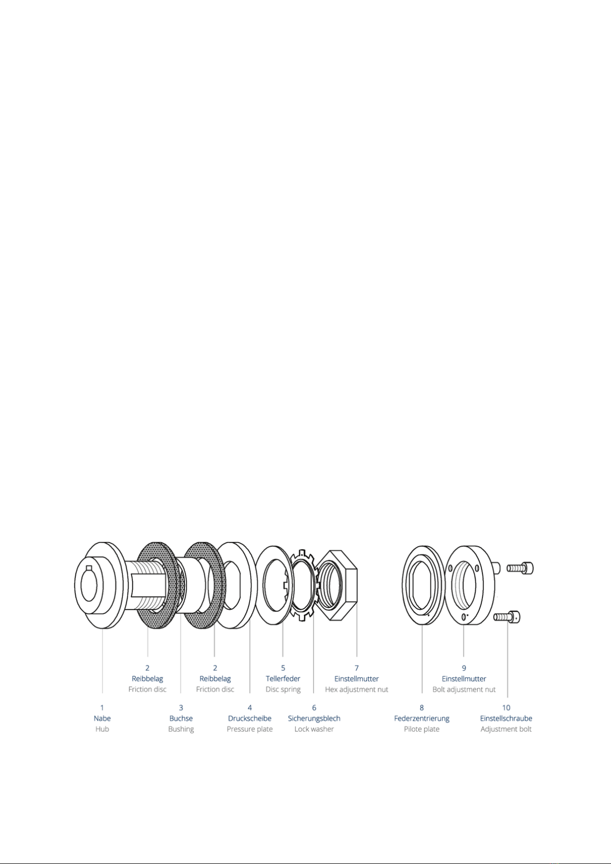
- Types with round nut with clamp screw (product no. 612 000 00 - 612 006 00):
The spring must be pre-loaded by turning the adjustment nut (60°-steps, see table on page 4).
The disk spring must not be completely flattened. After adjusting, the clamp screw must be
tightened by hand.
- Types with hexagon nut (product no. 612 010 00 - 612 040 00):
The spring must be pre-loaded by turning the adjustment nut (60°-steps, see table on page 4).
The disk spring must not be completely flattened. After adjusting, a few flaps of the lockwasher
must be bent.
- Types with round nut with axial bolts (Art.-Nr. 612 050 00 - 612 080 00):
First screw back the three adjustment bolts, so that they don´t protrude. Then hand tightening the
nut. Screw the three adjustment bolts fully into the nut. The maximum torque has now been set.
When a lesser torque setting is desired, the three adjustment screws have to be turned back into
the nut to allow the nut to be turned counterclockwise in 60° increments in accordance with the
table on page 4). Then the three screws have to be screwed completely into the nut again.
Locking after Torque Setting
The sizes 120 and 180 have a round nut with clamp screw. After adjusting, the clamp screw must
be tightened by hand. The sizes 250 and 350 have a crowned lock washer. After adjusting,
several flats must be bent to the nut. The sizes 500 and 700 have not a lock washer, but
adjustment bolts. After adjusting, these bolts must be tightened:
Size 500, screws M8: 18 Nm.
Size 700, screws M10: 38 Nm.
Date May 23rd 2024 Current on the internet at www.maedler.de Page 4 from 4
Running-in
Torque limiters should be run-in for the most consistent results. For this run-in period adjust the torque
limiter to 50 % of the desired torque and let the center member slip for about 4 minutes at 60 RPM.
Installation Conditions and Environmental Influences
It should be observed, that the torque limiter is protected against oil, dirt, dampness and rust to assure
its proper function.
Maintenance - Torque Testing
If it is necessary to obtain a precise torque setting, the following procedure is suggested. The torque
limiter should be mounted, prior to installation, in a vice held by the outer diameter of the center
member. With a short piece of shaft with key in the bore the torque can now be set by the use of a
torque wrench. This procedure can of course only be used in small size torque limiters.
From time to time the torque setting should be checked and, if necessary, it should be adjusted.
Torque Adjustment Table
Table of Torque Limiter Adjustment (in Nm)
1)
Limiter Type
HEX NUTS – CLOCKWISE MOVEMENTS IN 60° INCREMENTS
Art.-No.
0 2)
1
2
3
4
5
6
7
8
612 000 00
0,5
1,5
2,5
3,4
4,0
4,6
5,0
612 001 00
1
3
5
6,8
8
9,2
10
612 005 00
1
2
4
6
7
9
10
612 006 00
2
4
8
12
14
18
20
612 010 00
7
13
23
30
34
35
36
612 020 00
14
26
46
60
68
70
72
612 030 00
20
26
48
59
70
79
84
87
90
612 040 00
40
52
96
118
140
159
168
174
180
Limiter Type
NUT-COUNTERCLOCKWISE MOVEMENTS in 60° INCREMENTS
Art.-No.
0
1
2
3
4
5
6
7
8
9
10
11
12
612 050 00
300
280
253
218
176
126
69
50
612 060 00
600
560
506
436
352
252
138
100
612 070 00
690
673
664
635
606
560
515
450
387
302
217
144
115
612 080 00
1380
1346
1328
1270
1212
1120
1030
900
774
604
434
288
230
1) Smallest torque adjustable is between 0° and 60°.
2) These torque settings have been developed theoretically and may vary in practical application.

Other MÄDLER Industrial Equipment manuals

MÄDLER Accuride DZ 5417 Operating and maintenance instructions

MÄDLER

MÄDLER Accuride DZ 5417 Operating and maintenance instructions

MÄDLER Coupling SI Service manual

MÄDLER

MÄDLER Coupling SI Service manual

Popular Industrial Equipment manuals by other brands

HWR InoFlex VT-S 016 Translation of the original operating manual

HWR

HWR InoFlex VT-S 016 Translation of the original operating manual

McElroy 2CU Operator's manual

McElroy

McElroy 2CU Operator's manual

MIYAWAKI SV1 user manual

MIYAWAKI

MIYAWAKI SV1 user manual

Giebel Adsorber MA-R Assembly and maintenance instructions

Giebel

Giebel Adsorber MA-R Assembly and maintenance instructions

ABB HT607070 Operation manual

ABB

ABB HT607070 Operation manual

Pentair PARAGON EZ REEL Assembly instructions

Pentair

Pentair PARAGON EZ REEL Assembly instructions

Rexnord Thomas Tpack 52 Series Installation and Maintenance

Rexnord

Rexnord Thomas Tpack 52 Series Installation and Maintenance

ISHIDA WM-4000 manual

ISHIDA

ISHIDA WM-4000 manual

Dual Sieve Shaker D-4325 product manual

Dual

Dual Sieve Shaker D-4325 product manual

Siemens SIMATIC NET S7-1500 operating instructions

Siemens

Siemens SIMATIC NET S7-1500 operating instructions

HYDROLAB HLP Series user manual

HYDROLAB

HYDROLAB HLP Series user manual

OKU PS-01 operating instructions

OKU

OKU PS-01 operating instructions

ABB DODGE PARA-FLEX manual

ABB

ABB DODGE PARA-FLEX manual

Ferguson Enterprises ProFlo ACF3001CRT2 installation instructions

Ferguson Enterprises

Ferguson Enterprises ProFlo ACF3001CRT2 installation instructions

SCHUNK DPG-plus Series Assembly and operating manual

SCHUNK

SCHUNK DPG-plus Series Assembly and operating manual

ABB XAC26224 Operation manual

ABB

ABB XAC26224 Operation manual

CAB 4712 Service manual

CAB

CAB 4712 Service manual

SMC Networks JSXFE Series instruction manual

SMC Networks

SMC Networks JSXFE Series instruction manual

manuals.online logo
manuals.online logoBrands
  • About & Mission
  • Contact us
  • Privacy Policy
  • Terms and Conditions

Copyright 2025 Manuals.Online. All Rights Reserved.