Eckold KF 170 PD User manual

Date of issue: 2018-05-09 English
Illustrations and measurements unbinding. Subject to change without notice.
Translation of the original instructions
Op rating Instructions
ECKOLD KRAFTFORMER
KF 170 PD

Distributed by:
Trick-Tools
75 Truman Road
Pella, IA 50219
Phone:1-877-VAN-SANT
E-mail: sales@trick-tools.com
Here at Trick Tools we believe that our customers deserve the best
value in their tool and equipment purchases. We are constantly at
work searching out a variety of high quality, high performance tools
to oer at the best prices possible. Our commitment to you is that
we will not oer “cheap junk” anywhere on our website. You, the
customer, help us to evaluate our products constantly and as soon as
an ongoing quality issue is uncovered we will correct it or disconnue
that product immediately. We hope to earn your connued trust.

Kraftformer K 170 PD 2018-05-09 | ECKOLD AG 2
General information
1.1 Preface
These operating instructions are designed to familiarize the user with the machine/plant and
its designated use. The instruction manual contains important information on how to operate
the machine/plant safely, properly and most efficiently. Observing these instructions helps to
avoid danger , to reduce repair costs and downtimes and to increase the reliability and life of
the machine/plant.
The operating instructions must always be available wherever the machine/plant is in use.
These operating instructions must be read and applied by any person in charge of carrying out
work with and on the machine/plant.
– operation, including setting up, troubleshooting in the course of work, evacuation of
production waste, care and disposal of fuels and consumables.
– maintenance (servicing, inspection, repair) and/or
– transport
In addition to the operating instructions and to the mandatory rules and regulations for
accident prevention and environmental protection in the country and place of use of the
machine/plant, the generally recognized technical rules for safe and proper working must
also be observed.
1.2 Copyright
1.3 Validity of the operating instructions
Copying as well as handing over of this document, and the use or communication of the
contents thereof, is forbidden unless expressively authorized. Contraventions are liable to the
payment of damages. All rights are reserved in the event of the grant of a patent or the registration of a
design.
© Copyright - ECKOLD AG, CH-7203 Trimmis
Dear valued customer,
You have purchased an ECKOLD product, which is characterised by its high quality and durability. We
would like to congratulate on making this purchase. This product is sure to bring you
plenty of joy and provide great service during your day-to-day work. Our customer services
and sales staff are always happy to help if you have any technical questions.
ECKOLD Kraftformer buyback: If, one day, you no longer use your ECKOLD Kraftformer,
we would be willing to buy it back. Contact us for more information.
Telefon-Number 0041 81 354 12 70 or under [email protected].
These operating instructions are only valid for ECKOLD Kraftformer type K 170 PD.
1.4 CE-mark
This machine/plant has been designed, constructed and manufactured according to the
EG machine guidelines and the there to folloed alterations. Corresponding to the accordance
of the machine/plant with the valid guidelines, the CE symbol is affixed to the housing of the
machine and the declaration of conformity is enclosed in the delivery contents.
1 G n ral information

3
Kraftformer K 170 PD 2018-05-09 | ECKOLD AG
General information
1.5 Table of contents
Chapter Designation Page
1 General information ............................................................................................................ 2
1.1 Preface............................................................................................................................................ 2
1.2 Copyright ...................................................................................................................................... 2
1.3 Validity of the operating instructions........................................................................................ 2
1.4 CE mark ........................................................................................................................................ 2
1.5 Table of contents .......................................................................................................................... 3
1.6 Application of the operating instructions ................................................................................ 6
1.7 Warranty ...................................................................................................................................... 6
2 Technical data ...................................................................................................................... 7
2.1 Characteristic data........................................................................................................................ 7
2.2 Type plate ...................................................................................................................................... 7
2.3 Short Description.......................................................................................................................... 8
2.3.1 Purpose of use .............................................................................................................................. 8
2.3.2 orming capacity of the Kraftformer K 170 PD .................................................................... 8
2.4 Drive .............................................................................................................................................. 8
2.5 Mechanics...................................................................................................................................... 9
2.5.1 Dimensions and weight .............................................................................................................. 9
2.5.2 Ram postion .................................................................................................................................. 10
2.5.3 Working stroke ............................................................................................................................ 10
2.6 Painting.......................................................................................................................................... 10
2.7 Ambient temperature range........................................................................................................ 10
3 Fundamental safety instructions.......................................................................................... 11
3.1 Warnings and symbols ................................................................................................................ 11
3.2 Basic operation and designated use of the machine/plant ...................................................... 12
3.3 Possible misuse ............................................................................................................................ 13
3.4 Selecting personnel and personnel qualifications .................................................................... 13
3.5 Protective measures...................................................................................................................... 14
3.5.1 Danger zone .................................................................................................................................. 14
3.5.2 Required protective equipment (provided by the customer) ................................................ 16
4 Transport / Set up ................................................................................................................ 17
4.1 Required personnel ...................................................................................................................... 17
4.2 Sensivity ........................................................................................................................................ 17
4.3 Intermediate storage .................................................................................................................... 17
4.4 Packing .......................................................................................................................................... 17
4.5 Transport ...................................................................................................................................... 18
4.6 Delivery contents.......................................................................................................................... 19
4.7 Degree of Disassembly ................................................................................................................ 19
4.8 Unpacking / Setup of the machine ............................................................................................ 20
4.8.1 Unpacking / Setup of the machine (Apparatus head) ............................................................ 21
4.8.2 astening of Apparatus head ...................................................................................................... 21
4.8.3 Swivelling up of Apparatus head................................................................................................ 22
4.9 Workplace illumination .............................................................................................................. 23
4.10 Internal transport ........................................................................................................................ 24
4.11 Disassembly .................................................................................................................................. 24
4.12 Disposal.......................................................................................................................................... 24

Kraftformer K 170 PD 2018-05-09 | ECKOLD AG 4
General information
Chapter Designation Page
5 Construction and Operation ................................................................................................ 25
5.1 General Description .................................................................................................................... 25
5.2 Working method .......................................................................................................................... 25
5.3 Application areas .......................................................................................................................... 26
5.4 Tool Overview .............................................................................................................................. 26
5.5 Indicators and Controls .............................................................................................................. 27
5.5.1 Lever for single- or continuous stroke ...................................................................................... 27
5.5.2 oot switch for single- or continuous stroke ............................................................................ 28
6 Connection / nstallation...................................................................................................... 29
6.1 Required Personnel ...................................................................................................................... 29
6.2 Pneumatic connection ................................................................................................................ 29
6.3 Mounting / Dismantling of the forming tools.......................................................................... 30
6.4 Tool shelf ...................................................................................................................................... 30
7 Operation .............................................................................................................................. 31
7.1 Required Personnel ...................................................................................................................... 31
7.2 Setting into operation .................................................................................................................. 31
7.3 Standard operation ...................................................................................................................... 32
7.4 Processing of components .......................................................................................................... 33
7.5 Adjustable ram position .............................................................................................................. 34
7.6 Adjustment of ram ...................................................................................................................... 35
7.7 Ram stroke limitation .................................................................................................................. 36
7.7.1 Recommended Settings for Ram position and Stroke length ................................................ 37
7.8 Setting of best ram position for the clinching .......................................................................... 38
7.8.1 Clinching parameters .................................................................................................................. 40
7.9 Inadmissible working procedures .............................................................................................. 40
8 Maintenance .......................................................................................................................... 41
8.1 Required Personnel ...................................................................................................................... 41
8.2 General maintenance .................................................................................................................. 41
8.3 Inspection list................................................................................................................................ 42
8.3.1 Mechanical components.............................................................................................................. 43
8.3.1.1 Dirt accumulation (visual check) .............................................................................................. 43
8.3.1.2 Damage (visual check) ................................................................................................................ 44
8.3.1.3 Observe excessively noises .......................................................................................................... 44
8.3.1.4 Check the tools for damage ........................................................................................................ 44
8.3.1.5 Check the tools for secure fit ...................................................................................................... 44
8.3.1.6 Type plate and information sign existant and legible.............................................................. 45
8.3.2 Pneumatic components .............................................................................................................. 46
8.3.2.1 Check pneumatic connectors and cables for visible damages ................................................ 46
8.3.2.2 Check pneumatic switch- and control elements for visible damages.................................... 46
8.4 Maintenance.................................................................................................................................. 47
8.4.1 General information about maintenance .................................................................................. 47
8.4.2 Maintenance list............................................................................................................................ 47
8.4.3 Mechanical components.............................................................................................................. 48
8.4.3.1 Maintenance of standard forming tools .................................................................................... 48
8.4.3.2 Lubrication instruction................................................................................................................ 49
8.4.3.3 Air servicing unit.......................................................................................................................... 50

5
Kraftformer K 170 PD 2018-05-09 | ECKOLD AG
General information
Chapter Designation Page
9 Appendix .............................................................................................................................. 51
9.1 Index of abbreviations.................................................................................................................. 51
9.2 Directory of changes .................................................................................................................... 51
9.3 Symbols and pictograms.............................................................................................................. 52
9.4 Registration sheet for the operating hours ................................................................................ 53
9.5 EC DECLARATION O CON ORMITY ................................................................................ 54
10 Spare Parts Stock / Order of Spare Parts ............................................................................ 55
10.1 Spare Parts Stock .......................................................................................................................... 55
10.2 Order Information........................................................................................................................ 55
10.2.1 Example order .............................................................................................................................. 56
10.2.2 Order form .................................................................................................................................... 57
10.3 Customer Service Adress ............................................................................................................ 58
11 Machine Spare Parts List (MEL)........................................................................................ MEL-1
11.1 Kraftformer K 170 PD .......................................................................................................... MEL-1
11.2 Apparatus head K 170 PD .................................................................................................... MEL-2
11.3 Housing .................................................................................................................................... MEL-3
11.3.1 Housing .................................................................................................................................... MEL-4
11.3.2 Ram ........................................................................................................................................ MEL-5
11.3.3 Eccentric lever ........................................................................................................................ MEL-6
11.3.4 Return motion device .......................................................................................................... MEL-7
11.3.5 Covering ................................................................................................................................ MEL-8
11.3.6 Tool holder ............................................................................................................................ MEL-9
11.4 Stroke adjustment................................................................................................................ MEL-10
11.4.1 Adjusting handle.................................................................................................................. MEL-11
11.5 Pneumatic cylinder.............................................................................................................. MEL-12
11.6 Covering................................................................................................................................ MEL-14
11.6.1 Pneumatic control set ........................................................................................................ MEL-15
11.7 Pressure lever ...................................................................................................................... MEL-16
11.7.1 Repair kit Pressure link ...................................................................................................... MEL-17
11.8 Continuous stroke modul .................................................................................................. MEL-18
11.9 Pedestal ................................................................................................................................ MEL-20
11.10 Accessory parts .................................................................................................................... MEL-21

Kraftformer K 170 PD 2018-05-09 | ECKOLD AG 6
General information
1.6 Application of the operating instructions
This operating instruction have been written with a view to provide information in all aspects
for all persons commissioned to work with/on ECKOLD Kraftformer K 170 PD.
The provided operating instructions:
• Operating instructions
• Safety directives
• Maintenance instructions
• Trouble Shooting
• Machine Spare Parts List K 170 PD
• Declaration of Conformity K 170 PD
The operating instructions have been written with a view to provide information for the
operator and the maintenance personnel in production. The use and observance of the operating instructi-
ons
— facilitates the proper and safe operation of the machine/plant
— makes it easy to get to know the machine/plant
— avoids interference through improper operation
— increases the reliability during use
— increases the service lifetime of the machine/plant
— reduces downtimes and repair costs
The operating instructions must always be at hand in the vicinity of the machine/plant.
Operate the machine/plant only with exact knowledge of these operating instruction.
1.7 Warranty
ECKOLD experience as well as modern production procedures and highest demands
on quality guarantee a high reliability of the machine/plant.
ECKOLD is not liable for proper functioning of the machine/plant
• when operation does not correspond to the usual application
• when applications, other than described within the terms of contract, are done
The customer has no warranty claims:
• for faulty operation
• inadequate maintenance
• the use of wrong operating materials
ECKOLD guarantee and liability conditions of the general terms of trade will not be extended
in the foregoing directives. The safety regulations have to be observed unconditionally.
Use only original ECKOLD forming tools! Only ECKOLD spare parts should be used.
We reserve the right to alterations without prior notice in the course of the technical
developments.
or all inquiries please state the ECKOLD contract No./Serial No.
We wish you a lot of success with the ECKOLD Kraftformer type K 170 PD.

7
Kraftformer K 170 PD 2018-05-09 | ECKOLD AG
Technical data
2.1 Characteristic data
Product data
Product data Complete machine
Designation Kraftformer
Type KF 170 PD
Article-No. (without stand) 021.200.2500
Article-No. (with stand) 021.200.2502
Serial-No. ..........
Order-No. ..........
Year of manufactures ..........
Manufacturer data
Company ECKOLD AG
Street / No. Rheinstrasse 8
ZIP code / City CH-7203 Trimmis
Country Schweiz
Phone ++41– 81 354 12 70
Telefax ++41– 81 354 12 01
e mail [email protected]
Net www.eckold.com
Customer data
Company
Street / No.
ZIP code / City
Country
Phone
e Mail
2.2 Type plate
2 T chnical data
Pic. 2.2 - Type plate

Kraftformer K 170 PD 2018-05-09 | ECKOLD AG 8
Technical data
2.3.2 Forming capacity of the Kraftformer KF 170 PD
Mild steel 400 N/mm2 2,0 mm
Stainless steel 600 N/mm2 1,5 mm
Aluminium 250 N/mm2 2,0 mm
Copper 250 N/mm2 2,0 mm
2.3 Short Description
2.4 Drive
Drive air
Release Pedal
Working pressure max. 60 kN
Input pressure ~ 6 bar (87 psi)
Air consumption in continuous mode max 300 l/min.
Stroke frequency (dep. on setting) in
continuous mode ~150 - 250/min.
The air operated K 170 PD is the smallest of the ECKOLD Kraftformer machines. It can be switched to sin-
gle or continuous stroke and can form mild steel material up to 2.0 mm thickness. The single stroke operati-
on makes the K 170 PD ideal for correcting and adjusting jobs – and it can be used for punching, notching
and clinching (connecting of sheet metal and profile sections).
Please take into account the maximum forming capacity of each tool in the accompanying tool
catalogue.
2.3.1 Purpose of use
The machine ECKOLD Kraftformer type K 170 PD is to be used for cold forming of sheet metal and profile
sections up to the max. plate thickness mentionned under item 2.3.1.
Do not use the K 170 PD Kraftformer machine for any other purpose!
Original ECKOLD forming tools are available for reforming work.
Use only original ECKOLD forming tools!
The machine must NOT be used or modified for other work!

9
Kraftformer K 170 PD 2018-05-09 | ECKOLD AG
Technical data
232 mm
560 mm
600 mm
241
140
186
4 x d11
146 mm
(22.047 inch)
(9.134 inch)
(23.622 inch)
(5.748 inch)
170
(6.693 inch)
105 - 97 mm
(19.882 inch)
790 mm
1545 mm
1060 mm
505 mm
(31.10 inch)
(60.827 inch)
(41.732 inch) (4.134 - 3.819 inch)
2.5 Mechanics
2.5.1 Dimensions and weight
Length 790 mm
Width 505 mm
Height 1545 mm
Throat, horizontal
(to the front edge of tool holder) 170 mm
Throat, vertical 146 mm
Working height with standard tools WA/ WR ~ 1100 - 1150 mm
Weight (without stand) ca. 93 kg
Weight (with stand) ca. 151 kg
• with stand • without stand
Kraftformer K 170 PD 2018-05-09 | ECKOLD AG 10
Technical data
2.6 Painting
Apparatus head light blue , RAL 5012
textured coating (without silicon)
Pedestal sapphire , RAL 5003
textured coating (without silicon)
2.7 Ambient temperature range
Operating ambient temperature -20°C ..... +55°C
Storage and transport temperature -25°C ..... +70°C
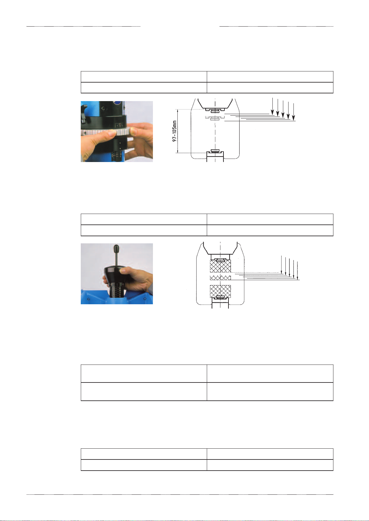
2.5.3 Working stroke
Adjustable stroke length 2 - 6 mm (by adjusting handle)
Steps of stroke length 0.05 mm
+/- 0.05 mm
2.5.2 Ram postion
Area of the ram adjustment 8 mm (by Handwheel)
Steps of the ram adjustment 0.1 mm
+/- 0.1 mm
11
Kraftformer K 170 PD 2018-05-09 | ECKOLD AG
undamental safety instructions
—
Cause:
The "Cause" column contains information regarding the type of danger and its
source.
—>
Consequence:
The "Consequences" row lists the possible consequences if the instructi-
ons are not adhered to.
• Protective measures:
The lines that are marked with a dot contain mandatory
instructions that must be strictly adhered to in order to prevent the above
consequences.
iMPORTANT indicates tips and other instructions that are particularly useful.
3.1 Warnings and symbols
The following signs and designations are used in the manual to designate instructions of
particular importance.
3 Fundam ntal saf ty instructions
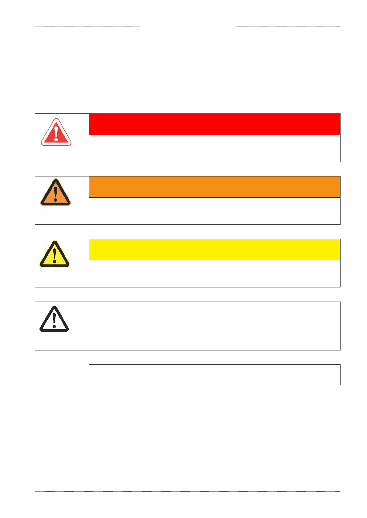
DANGER Indicates an imminent potential danger. If no suitable measures are
taken, death or serious injuries will occur.
— Cause
—> Consequence
• Protective measures
WARN NG indicates a potentially dangerous situation. If it is not avoided, death or
serious injury might be the consequences.
— Cause
—> Consequence
• Protective measures
CAUT ON indicates a potentially dangerous situation. If it is not avoided, minor
injuries might be the consequences.
— Cause
—> Consequence
• Protective measures
ATTENT ON indicates a potentially damaging situation. If it is not avoided, the
machine or property close to it might be damaged.
— Cause
—> Consequence
• Protective measures

Kraftformer K 170 PD 2018-05-09 | ECKOLD AG 12
3.2 Basic operation and designated use of the machine/plant
The product has the following type designation:
— K 170 PD (Kraftformer)
The product was designed for the following production processes:
— Reforming sheets and profiles made of steel, stainless steel, aluminium or similar materials
The product is a complete machine.
The following accessoires are required for the operation:
— Tools
The machine/plant has been built in accordance with state-of-the-art standards and the
recognized safety rules. Nevertheless, its use may constitute a risk to life and limb of the user or of third par-
ties, or cause damage to the machine and to other material property.
The machine/plant must only be used in technically perfect condition in accordance with its
designated use and the instructions set out in the operating manual, and only by safety-conscious persons
who are fully aware of the risks involved in operating the machine/plant.
Any functional disorders, especially those affecting the safety of the machine/plant, should therefore be recti-
fied immediately!
The ECKOLD-Kraftformer K 170 PD has been designed exclusively for the driving of ECKOLD-tools for
the non-cutting cold shaping of sheet metals and profiles.
Applications other than those described here are not regarded as proper use. The manufacturer/supplier is
not liable for damages resulting from a use in this way. The user is solely responsible for this risk. Operating
the machine within the limits of its designated use also involves observing the instructions set out in the ope-
rating manual and complying with the inspection and maintenance directives.
Change to the normal use by the operator is forbidden!
Changes to the technical data (see chapter «Technical Data» on page 9) by the operator are forbidden!
The operating instructions must always be at hand in the vicinity of the machine/plant!
Operate the machine/plant only with exact knowledge of these operating instruction.
WARN NG
— Change to the normal use by the operate
—> Risk of injury to personnel and damage to the product
• Please contact the product manufacturer if you would like to change the normal use.
undamental safety instructions

13
Kraftformer K 170 PD 2018-05-09 | ECKOLD AG
3.3 Possible misuse
The machine must be installed and serviced only by authorized personnel.
The machine must not be modified or altered in any way without authorization.
The operation and preventive maintenance of the machine as described in the operation
manual must be performed only by authorized and trained personnel.
As a general rule, the machine may be operated in Normal mode only if all safety features are
present, properly installed and fully functional.
The machine may be operated in other operating modes (Maintenance mode) requiring the
removal of certain safety features only while the personnel pays extra attention and if it is
ensured that all safety features are properly replaced and their function checked immediately
after the work has finished.
All problems and damages indicated by the system or detected otherwise must be reported
and eliminated immediately.
None of the conditions defined for the intended use, such as performance data (pressures,
dimensions, weight, etc.) or materials, may be altered.
The machine must not be operated by personnel that does not meet the requirements defined
in this operation manual (see chapter 3.4 „Selecting personnel and personnel qualifications“
on page 13).
Bypassing valves and other control components is prohibited
WARN NG
— Personnel who have not been trained, or who have not read the operating
manual, work on/with the product
—> Life-threatening hazards for personnel, injury hazards for personnel, Damage to the
product
•
Owner:
Only assign personnel to work with/on the machine who have been trained
in the tasks of the relevant operating phase and/or have read the operating manual.
Provide training for your personnel for the handling of the machine so that all
instructions in the operating manual are observed. Ensure that the operating manual is
available to your personnel so that they can familiarize themselves with the content.
•
Personnel:
ollow all instructions listed in the operating manual.
3.4 Selecting personnel and personnel qualifications
The owner of the machine (Machine) is responsible for correctly selecting personnel and
qualification of personnel for working on/with the machine.
undamental safety instructions
Kraftformer K 170 PD 2018-05-09 | ECKOLD AG 14
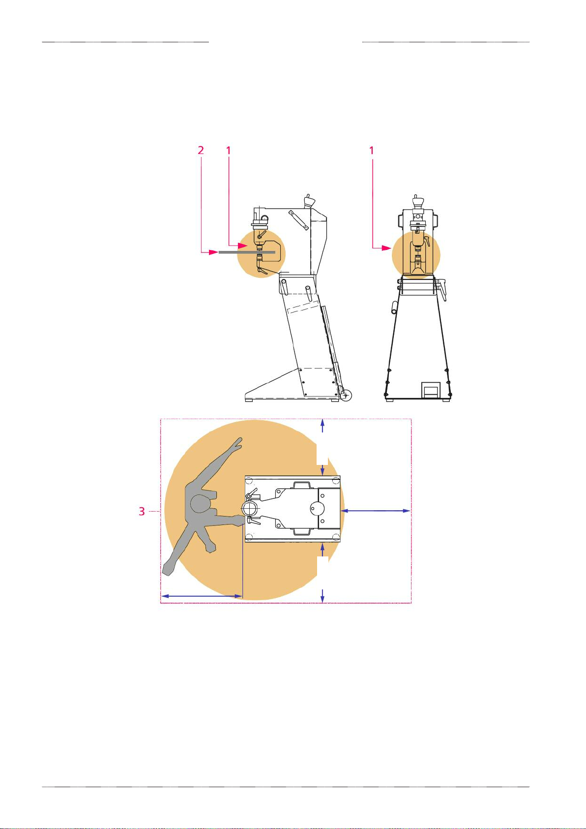
3.5 Protective measures
The following areas are danger zones of the product:
1 In the working range of the ram, in particular between the tools
2 On the component (metal sheet) which is to be processed
3 In the whole access area around the product
3.5.1 Danger zone
500 mm
500 mm
500 mm
500 mm
Danger area
(Operator
work station)
< 1,5 m
undamental safety instructions

15
Kraftformer K 170 PD 2018-05-09 | ECKOLD AG
The following dangers exist:
Danger zone 1
— Crushed upper extremities (e.g. fingers, hands, arms)
WARN NG
—Reaching into the danger zone during working movements. In the working
range of the ram, in particular between the tools
—> Crushed upper extremities (e.g. fingers, hands, arms)
• Do not reach into danger zone during working movements.
• During working movements, prevent others from reaching into the danger zone
CAUT ON
—Sharp edges on component (sheet metal) which is to be processed
—> Cuts to upper extremities
• Always wear protective gloves when processing components on the Kraftformer
Danger zone 2
— Cuts to upper extremities
Danger zone 3
— Damage to vision
WARN NG
—Flying splinters while components are being processed, particularly at high
machining forces
—> Damage to vision, injury to personnel
• Always wear eye protection when processing components on the Kraftformer.
Persons in jeopardy
Persons in jeopardy include all those who are wholly or partially located in the hazard area.
Operating personnel
Operating personnel include the following people:
— Personnel who have been assigned with operation, including charging, malfunction
resolution in the work process, disposal of production wastes, care, disposal of operating
materials and auxiliary materials.
— Personnel who have been assigned with maintenance (service, inspection, repair).
— Personnel who have been assigned with transport.
undamental safety instructions

Kraftformer K 170 PD 2018-05-09 | ECKOLD AG 16
Eye protection
Always wear eye protection when processing components on the Kraftformer.
iMPORTANT
• As the owner, it is your duty to ensure that operators are provided with the following
protective equipment in order to use the product safely.
3.5.2 Required protective equipment (provided by the customer)
Protective gloves
Always wear protective gloves when processing components on the Kraftformer.
Safety boots
Always wear safety shoes when processing components or when changing tools.
undamental safety instructions

17
Kraftformer K 170 PD 2018-05-09 | ECKOLD AG
Transport / Set up
4.4 Packing
The way of transport is decisive for the type of packing.
• Observe the appropriate transport notes on the packing.
iMPORTANT
• Inspect the package for visible damage and journalize them at the acceptance oft the
delivery by the carrier.
• In sever damage inform immediately your transport insurance to secure your claim on
compensation for damages.
Set forklift here keep dry this side up
4 Transport / S t up
4.1 Required personnel
4.2 Sensivity
Well trained and qualified personnel with the following knowledge must be used.
Training:
Transport / Set up
Training and / or read of the chapter of the manual:
03 undamental safety instructions, 04 Transport / Set up
4.3 ntermediate storage
If the machine/plant is not operated immediately after delivery, then it must be stored in a protected area
dust-free and dry. A special preservation should be undertaken, if an intermediate storage time of more than
two months is foreseen.
ATTENT ON
— Carefree transport of the product (K 324)
—> Damage to the product
• During the transport avoid condensation of water due to temperature fluctuations and
vibrations due to force or careless loading and unloading.
Kraftformer K 170 PD 2018-05-09 | ECKOLD AG 18
Transport / Set up
• Transport the product to its installation site using appropriate means of transportation.
• Do not lift the product with a forklift or crane if the packaging is damaged.
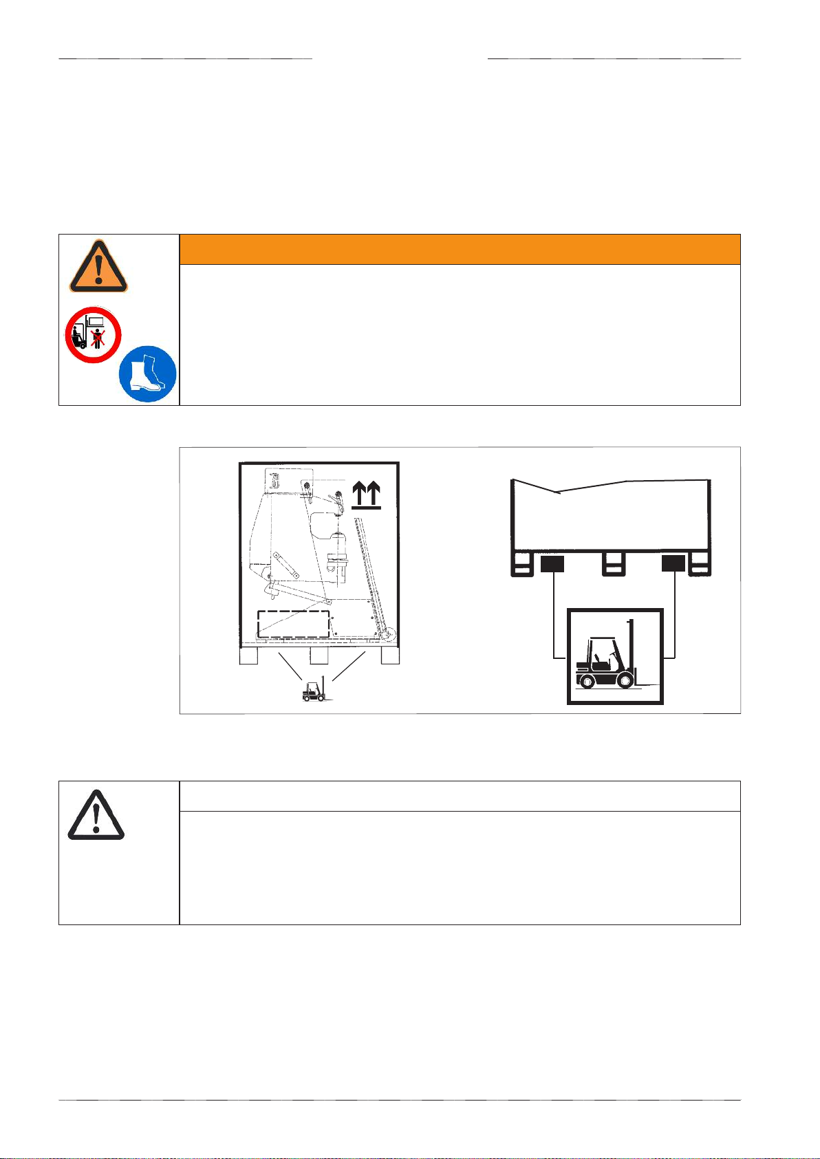
4.5 Transport
Picture 4.5 - Transport with a fork lift truck
ca. 180 kg
WARN NG
— Lifting the product with a forklift without sufficient carrying capacity
— Staying underneath the suspended product
—> If the product falls: Risk of death or injury to personnel, damage to the product
• Only use a forklift with sufficient carrying capacity to lift the product.
• Do not hang around near or underneath the product during transportation.
• Wear protective boots to protect your feet.
Transport with a fork lift truck:
• Adjust the forks of the forklift to the maximum possible width!
The centre of gravity of this unit is quite high. Danger of tilting! Please handle with extreme care to avoid
damages and/or injuries.
ATTENT ON
— There is a danger of the product falling when being carried by a forklift up and
down ramps
—> Damages on the product
• Drive up and down ramps with extra caution. Only drive along routes released for for
klifts.

19
Kraftformer K 170 PD 2018-05-09 | ECKOLD AG
Transport / Set up
4.7 Degree of Disassembly
The following work must be carried out in order to create operational conditions:
1. Set up of the machine (see page 22)
2. Connection / Assembly (see page 31)
• ollow all instructions in the respective sectors.
• Immediately check the completeness of the delivery upon receipt. Compare the range of
delivery with the enclosed delivery documents. Possible transport damages and/or missing
parts must be reported immediately in writing.
4.6 Delivery contents
iMPORTANT
Tools are not part of the product's delivery scope. However, tools can be part of the
delivery scope of the delivery order.
Kraftformer K 170 PD Operating instructions
and tool catalogue,
Instructions for unpacking
1 Grease gun
1 Hexagon srew driver
DIN 911, SW5
1 piece ork wrench
SW 17 DIN 894
1 piece ork wrench
SW 24 DIN 894
(only for delivery
K 170 PD with stand)
This manual suits for next models
2
Table of contents
Popular Lathe manuals by other brands


Scheppach
Scheppach DM600VARIO Translation of original instruction manual

Hafco Metalmaster
Hafco Metalmaster CL-68A instruction manual

AXMINSTER WORKSHOP
AXMINSTER WORKSHOP AW368WL Original instructions

Jet
Jet JWL-1236 Operating instructions and parts manual

Rikon Power Tools
Rikon Power Tools 70-3040 Operator's manual

Grizzly
Grizzly T10810 instructions


