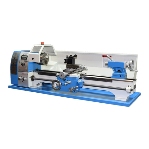
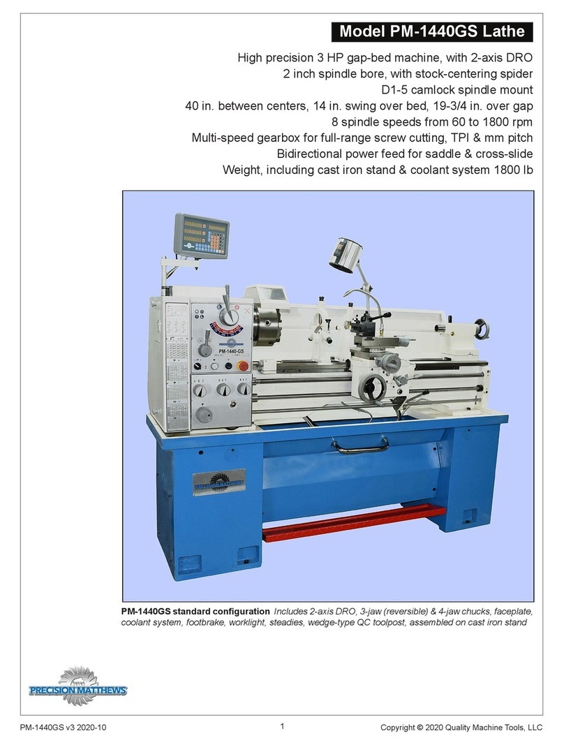
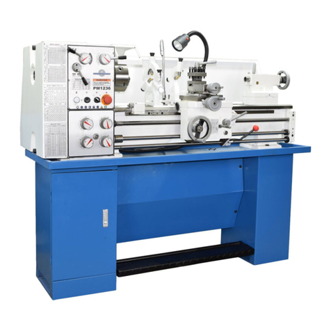
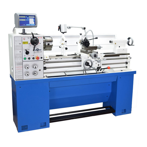
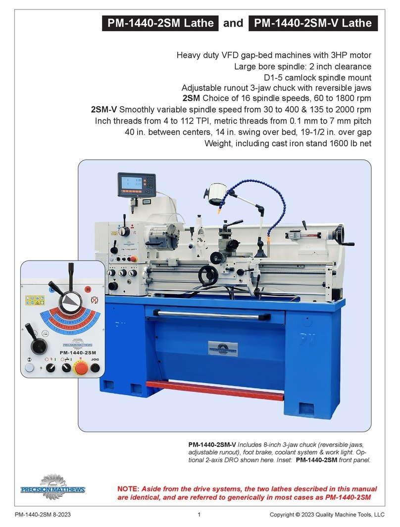
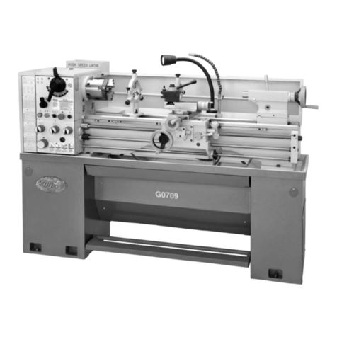
Precision matthews PM-1127VF-LB User manual

1
PM-1228VF v3 2021-05 Copyright © 2021 Quality Machine Tools, LLC
Model PM-1228VF-LB Lathe
110 Vac 2 HP heavy-duty machine
Variable spindle speed from 50 - 2000 rpm
Large 1-1/2 in. bore spindle
D1-4 camlock spindle mount
28 in. between centers, 12 in. swing over bed
Multi-speed gearbox for full-range screw cutting, TPI & mm pitch
Bidirectional power feed for saddle & cross-slide
Weight, excluding stand 490 lb
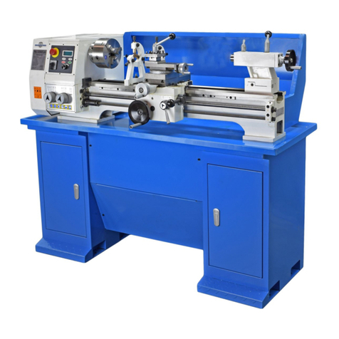
PM-1228VF-LB shown with 3-jaw chuck, steady rest
and traveling rest. Installed on optional stand.

2Copyright © 2021 Quality Machine Tools, LLCPM-1228VF v3 2021-05
PM-1228VF-LB
FAQ
This manual contains essential safety advice on the proper setup, operation, maintenance, and service
of the PM-1228VF-LB lathe. Failure to read, understand and follow the manual may result in property
damage or serious personal injury.
There are many alternative ways to install and use a lathe. As the owner of the lathe you are solely
responsible for its proper installation and safe use. Consider the material contained in this manual to
be advisory only. Quality Machine Tools, LLC cannot be held liable for injury or property damage during
installation or use, or from negligence, improper training, machine modications or misuse.
This manual describes PM-1228VF-LB machines as shipped from late 2016. There may be detail dierenc-
es between your specic machine and the information given here (with little or no impact on functionality).
Please email us if you have questions about any aspect of the manual or your machine (see our website
www.precisionmatthews.com for support addresses). Your feedback is welcomed!
This material was originated by Precision Matthews. No portion
of the manual may be reproduced or distributed in any form
without the written approval of Quality Machine Tools, LLC.
The lathe doesn’t run
(1)
Power switch set to 1?
(0is OFF, 2powers an
outlet on the back panel)
The lathe doesn’t run
(2)
E-Stop button pressed in?
Twist to release it —should
pop up.
The lathe doesn’t run
(3)
End cover closed?
The spindle always turns
forward
This is the default condition
when the start button (green)
is pressed following power
up. Press the left hand white
button to change direction.
Can’t operate power feed
Split nut lever too far right?
Go to the detent position,
just short of the end stop.
Saddle handwheel
doesn’t move the
saddle
Push the handwheel in
to engage the rack
2

3
PM-1228VF v3 2021-05 Copyright © 2021 Quality Machine Tools, LLC
Section 1 INSTALLATION
THESE ARE THE MAIN POINTS TO WATCH OUT FOR!
But read the following pages for more information
• Handling the lathe is at least a two-man job.
• Lifting gear – sling, hoist or forklift – must be rated for at least 1/2 ton.
• Care must taken when lifting to avoid exing or other damage to any component of the
lathe, especially the leadscrew and hex-section feed shaft.
• Working location of the lathe must allow space for opening drive system cover at left;
also, access to the electrical box at the back of the headstock.
• Power requirement is 110V, 60Hz, single phase, 20A circuit.
• Extension cord not recommended; if no alternative, use 12 AWG not longer than 20 ft.
• Before connecting power be sure that:
1. The machine is on a rm footing.
2. Chuck camlocks tight, no wrench left in chuck.
3. Saddle and cross slide approx. mid-travel, power feed disengaged (Figure 3-18, etc.).
4. The speed control knob is set for a low or zero spindle speed, fully counter clockwise.
Check oil level in the gearbox before use
SETTING UP THE LATHE
The PM-1228VF-LB is shipped in two packing cases, one for
the lathe, one for the optional stand. When installed on the
stand, the machine can be lifted in one piece by an overhead
hoist or forklift with slings and/or chains, all items rated for a
total weight of at least 1/2 ton. A suggested setup for lifting is
shown in Figure 1-1.
When selecting a location for the lathe, allow sucient room at
the right to allow removal/servicing of the leadscrew and feed
shaft. At the back of the machine allow access for installation
of DROs, etc.
Be sure to keep all lifting gear clear of any part of the lathe,
especially the two shafts at the front. If necessary keep
the sling away from the shafts using “2-by” spreaders.
Figure 1-1 Lifting with slings
In this setup the sling was looped through holes in the lathe bed. If
instead the sling is set across and under the lathe bed, use spreaders
to keep the sling clear of all components — especially the front shafts.
Before lifting, protect the bed, then remove the chuck if in-
stalled. Move the tailstock and saddle as far to the right as
possible to balance the machine at the point(s) of suspension.
With the lathe in its permanent location, level it using metal
shims under the cabinets, or (preferred), install 150 lb rated
leveling mounts in the mounting holes of the two stand cabi-
nets, 4 for the left hand cabinet, 2 for the right.
LEVELING
The following procedure ensures that the lathe bed is in the
same state as it was when the lathe was checked for accuracy
in manufacture — level from end to end along the bed, and
from front to back. In other words, no warping.
For a stable installation, make sure all leveling mounts and/
or shims are properly weight bearing, rmly in contact with
the oor. Check and adjust level from end to end using a pre-
cision machinist’s level, if available. If not, use the most reli-
able level on hand. Check and adjust across the bed using a
matched pair of spacers such as 1-2-3 blocks to clear the Vee
tenons. Alternatively, check for level on the ground surface of
the cross slide as the carriage is traversed from end to end,
Figure 1-2. See also “Aligning the Lathe” in Section 3.
4Copyright © 2021 Quality Machine Tools, LLCPM-1228VF v3 2021-05
The mounts shown in Figure 1-3, available from Precision Mat-
thews, allow leveling adjustment from above. If installing on
the PM1228 stand, 8 leveling mounts are required — 4 for the
left hand cabinet, 4 for the right. Because there is insucient
headroom in the stand pockets, the threaded stems need to be
shortened by about 1-1/2”. Before installing, oil the threads in
each mount then bottom the stem (8 mm wrench) to be sure
the pressure plate is able to expand the molded base. If neces-
sary use a strap wrench to stop the cup from rotating.
Place the cup under the stand, with washer and locknut above
the stand footplate. Because an 8 mm wrench has only a small
Figure 1-2 Check level in both axes
Check level of the cross-slide at headstock and tailstock ends — if
there is no twisting of the bed the indication should be the same. To
check the left to right axis rest the level on a precision ground bar, as
here.
Figure 1-3 Top-adjusting leveling mount (optional)
Pusher plate
Washer
M12 x 1.75 x 50 mm
hex head screw
Molded base
Locknut
Stand footplate
Cup stamping
Weld nut
amount of leverage, it may be more convenient to replace the
threaded stems with hex head screws (M12 x 1.75). Screw
length should be 50 mm, but 45 mm (even 40 mm) will do
if the oor is reasonably level. Adjust using a 19 mm or 3/4”
ratcheting wrench.
CLEANUP
Finished metal surfaces may be protected by thick grease and/
or paper. Carefully remove these using a plastic paint scrap-
er, disposable rags and a light-oil such as WD-40. Be sure to
remove paint over-spray from surfaces that may aect sliding
motion, such as under the bed ways.
POWER REQUIREMENT
Plug the supplied cord into a standard 110V ac outlet,
minimum capacity 20 Amps.

5
PM-1228VF v3 2021-05 Copyright © 2021 Quality Machine Tools, LLC
General information
The PM-1228VF-LB features a high-torque 2 HP brushless DC motor giving smoothly variable spindle speeds in
two ranges, from 50 to 1000 rpm and 100 to 2000 rpm. Power requirement is 110 V, 60Hz. The lathe ships fully
assembled, net weight 490 lb. A sheet metal stand with two cabinets is available as an option.
The spindle has a 1-1/2 inch bore and is unusually short, ideal for through-spindle work. Long service life is assured
by high precision taper-roller spindle bearings, together with hardened and ground bed ways, shafts and headstock
gears. All internal gears in the machine are oil-bath lubricated.
A saddle-feed gearbox, together with a set of external change gears, provides for a full range of UNC and UNF
threads from 5 to 72 TPI, and metric threads from 0.5 to 4 mm pitch. The leadscrew is quickly reversible for left
hand threading.
The saddle-feed gearbox also drives an independent hex-section feed shaft to power the saddle and cross-slide in
both directions. Like the leadscrew, the saddle/cross-slide feed shaft can be quickly reversed. An adjustable dog
clutch on the feed shaft allows the saddle to be stopped precisely at any point along the bed. All internal gears in
the saddle-feed gearbox are continuously splash-lubricated.
Section 2 FEATURES & SPECIFICATIONS
MODEL PM-1228VF-LB Lathe
PM-1228VF-LB Floor plan: approximate dimensions (not to scale)

6Copyright © 2021 Quality Machine Tools, LLCPM-1228VF v3 2021-05
Everyday precautions
• This machine is intended for use by experienced users familiar with met-
al-working hazards.
• Untrained or unsupervised operators risk serious injury.
• Wear ANSI-approved full-face or eye protection at all times when using the
machine (everyday eyeglasses are not reliable protection against ying parti-
cles).
• Wear proper apparel and non-slip footwear – be sure to prevent hair, cloth-
ing or jewelry from becoming entangled in moving parts. Gloves – including
tight-tting disposables – can be hazardous!
• Be sure the work area is properly lit.
• Never leave chuck keys, wrenches or other loose tools on the machine.
• Be sure the workpiece, toolholder(s) and machine ways are secure before
commencing operations.
• Use moderation: light cuts, low spindle speeds and slow table motion give
better, safer results than “hogging”.
• Don’t try to stop a moving spindle by hand – allow it to stop on its own.
• Disconnect 110 Vac power from the lathe before maintenance operations such
as oiling or adjustments.
• Maintain the machine with care – check lubrication and adjustments daily
before use.
• Clean the machine routinely – remove chips by brush or vacuum, not com-
pressed air (which can force debris into the ways).
No list of precautions can cover everything.
You cannot be too careful!

7
PM-1228VF v3 2021-05 Copyright © 2021 Quality Machine Tools, LLC
Dimensions, approximate overall, incl. stand
Width 59 in. x Height 49 in. x Depth 28 in.
Footprint (excluding handles): Width 56 in. x Depth 20 in.
Bed length, excluding headstock: 42 in.
Bed width: 6-1/4 in.
Spindle centerline to oor (on stand): 44 in.
Weight, approximate:490 lb net, with stand 600 lb net
Power requirement 110 Vac, 60 Hz, 1Ø, 20A circuit
Motor 2 HP (1500 W) brushless dc
Work envelope
Headstock center to tailstock center 28 in. max
Swing over bed 12 in. diameter
Swing over cross slide 7 in. diameter
Spindle face to tailstock quill face 30 in. max
Saddle travel along bed 24 in.
Cross-slide travel 6 in.
Compound (top slide) travel 3-1/4 in.
Drive system DC drive with 2-speed Vee pulleys
Low range, rpm 50 to 1000
High range, rpm 100 to 2000
Saddle drive, thread cutting Leadscrew 8 TPI, 3/4 in. diameter
Inch threads Choice of 27, from 5 to 72 TPI (including 13 TPI)
Metric threads Choice of 14, from 0.5 mm to 4 mm pitch
Saddle / cross slide drive, turning & facing Separate feed shaft, hexagonal cross-section
Turning operations Choice of feed rates from 0.0016 to 0.0115 in./spindle rev
Facing operations Choice of feed rates from 0.0008 to 0.0061 in./spindle rev
Spindle
Chuck/faceplate attachment D1-4 Camlock
Internal taper MT5
Spindle bore 1-1/2 in.
Spindle length, LH end to D1-4 chuck mounting face 14-1/2 in. approx.
Spindle length, LH end to chuck face (typical) 17-1/2 in. approx.
Tailstock
Internal taper MT3
Quill 1-1/4 in. diameter, 4 in. travel
Work holding (typical)
3-jaw chuck, 6-1/4 in. approx.
4-jaw chuck, 8 in. (option)
Faceplate 10 in. (option)
Center rest (steady rest) capacity Up to 2-3/4 in. diameter
Follower rest capacity Up to 1-3/4 in. diameter
PM-1228VF-LB SPECIFICATIONS

8Copyright © 2021 Quality Machine Tools, LLCPM-1228VF v3 2021-05
DRIVE SYSTEM
Two-speed pulleys and a Vee belt connect the high-torque
brushless dc motor direct to the spindle, Figure 3-1. The low
speed coupling gives spindle speeds from 50 to 1000, high
speed from 100 to 2000 rpm. Many users will nd that the low
range is suitable for much of their work, so there is rarely a
need to recongure the drive.
To change speed loosen the M8 hex head screw securing the
idler pivot plate. Reposition the belt, then adjust the idler so
that rm gure pressure mid-way between the pulleys deects
the Vee belt about 1/4” — no tighter than that.
MOTOR CONTROLS
Figure 3-3 shows the simple user interface made possible by
the combination of dc motor and smart motor controller.
Figure 3-1 Vee belt and pulleys
Figure 3-3 Motor controls & tachometer display
Figure 3-2 110 Vac outlet & circuit breaker
The outlet is for an independent attachment such as
a milling head. It is not live when the lathe is in use.
Motor control buttons
Set the power switch to 1
Press the GREEN (I) button to run the motor.
Press the RED (O) button to stop the motor.
Spindle direction buttons
Press the RIGHT button for FORWARD, counter-clockwise ro-
tation of the spindle (as viewed from the tailstock); this is the
usual direction for turning operations. Press the LEFT button
for REVERSE, clockwise rotation.
Switch from forward to reverse, or vice versa, without
pausing, or powering-down. The motor controller brakes
the spindle electronically to zero, then spools up in the
opposite direction to the same speed as before.
Speed control
This is a potentiometer. Set it fully counter-clockwise for min-
imum speed.
Speed display (tachometer)
This is a 4-digit LCD that continuously monitors spindle speed
in revolutions per minute (rpm). When the lathe is powered on
(power switch to 1), the LCD is lit.
Section 3 USING THE LATHE
The PM-1228VF-LB is a conventional engine lathe that re-
quires little explanation except for details specic to this partic-
ular model — speed selection, thread cutting, and the saddle/
cross-slide power feed system. The user is assumed to be
familiar with general purpose metal lathes.
Those unfamiliar with lathe work may nd the following helpful:
HOW TO RUN A LATHE, published many years ago by the
original South Bend Machine Works (not the current owners
of the brand), with many revisions through the 1960s. This is
the classic go-to source for lathe users of every level of expe-
rience.
Power switch
1 = ON
0 = OFF
2 = 110 Vac outlet on
back panel
Speed
control
Speed display (tachometer)E-Stop button
STOP
motor
RUN
motor
Spindle RE-
VERSED
Spindle
FORWARD
Power switch
Select 1to connect power to the lathe
Select 0 to disconnect power
Select 2to connect 110 Vac power to the outlet at rear of the
electrical box (female C13 outlet, IEC 60320, Figure 3-2).
The tachometer display should light when power is on
Before doing ANYTHING, be sure nothing will be
thrown o or damaged when the motor runs —
Chuck? Chuck Key? Power feed disengaged?
Safety feature ...
The lathe will not run unless the cover at left of the headstock
is closed. A metal tongue attached to the inside of the cover
closes the safety switch, Figure 3-20.
The spindle direction on powering-up is always forward.

9
PM-1228VF v3 2021-05 Copyright © 2021 Quality Machine Tools, LLC
Figure 3-4 Spindle speed sensor
The speed display is unlit when the power switch is OFF (0), or
if the Emergency Stop (E-Stop) button is pressed. When pow-
er is restored following either of those conditions, the LCD dis-
plays 0000 — motor stationary — until the RUN motor button
is pressed and the speed control knob adjusted to the desired
setting. (This is a safety measure to ensure that a previous
speed is NOT resumed automatically following what could be
an uncorrected fault condition.)
Input to the tachometer is from a sensor in the spindle cavity of
the headstock, Figure 3-4.
The display may alternate ± a few rpm when the spindle is
running at constant speed. This is to be expected, and is not
a fault condition.
CHUCKS & FACEPLATE
The spindle nose on the PM-1228VF-LB accepts D1-4
Camlock chucks, faceplates and other work holding devices.
A D1-4 chuck or faceplate is held by three threaded studs,
each with a D-shape crosscut to engage a corresponding cam
in the spindle nose, Figure 3-6. The function of the cams is
to pull the chuck backplate inward to locate its internal taper
rmly on the spindle nose.
Figure 3-6 Camlock stud
Emergency Stop button
Slap the E-Stop button with the palm of the hand to disconnect
power instantly. The button pops out when twisted clockwise
a few degrees. This restores power, but does not activate the
motor (see Speed display above).
Alongside each stud is a stop screw, the head of which ts
closely in a groove at the threaded end of the stud. The func-
Figure 3-5 D1-4 three-jaw chuck
TO INSTALL A CHUCK
Disconnect the 110V supply from the lathe!
Chucks and faceplates are heavy — 6 in. chucks can weigh
more than 20 lb. They will cause serious damage if allowed
to fall. Even if a chuck is light enough to be supported by one
hand, the lathe bed should be protected by a wood scrap, as
Figure 3-7.
Figure 3-7 Protect the lathe bed
Some users add packing pieces, even custom-made cradles,
to assist “straight line” installation and removal. Before install-
ing make certain that the mating surfaces of the chuck/face-
plate and spindle are free of grit and chips.
The cams on the spindle are turned with a square-tip wrench
similar to the chuck key (may be same tool in some cases).
Recommended procedure:
1. Turn the spindle by hand, checking that all three cam mark-
ers are at 12 o’clock, Figure 3-8.
2. While supporting its full weight, install the chuck with-
out tilting, then gently turn each of the cams clockwise —
snug, rm, but not locked tight in this rst pass.
3. Check that each of the cam markers lies between 3 and
6 o’clock, between the two Vees stamped on the spindle,
Figure 3-9.
tion of the stop screw is NOT to clamp the stud in place, but
instead to prevent it from being unscrewed when the chuck is
not installed.
Never leave the chuck key in the
chuck, not even for a second!

10 Copyright © 2021 Quality Machine Tools, LLCPM-1228VF v3 2021-05
TO REMOVE A CHUCK
Disconnect the 110V supply from the lathe!
Protect the lathe bed, as Figure 3-7. While supporting the
weight of the chuck, turn each of the cams to 12 o’clock, Figure
3-8, then remove the chuck. If the chuck does not come free,
Figure 3-9 Cam in locked condition
If any cam marker is not within the Vees, rst be sure that
there is no gap between chuck backplate and spindle ange.
Also, remove the chuck to inspect the studs — burrs can be a
problem, hone if necessary. If there are no visible problems,
the stud in question may need adjustment as follows:
• Remove the stop screw from the stud.
• If the cam marker in question can’t get to the rst Vee (3
o’clock), back the stud OUT one full turn, then replace the
stop screw.
• If the cam marker goes beyond the second Vee (6 o’clock),
screw the stud IN one more turn, then replace the stop
screw.
• If the markers are correctly aligned, repeat the tightening
sequence as Step 2 above, light force. Repeat the se-
quence two more times, rst with moderate force, then fully
tighten.
Figure 3-10 Saddle handwheel
CROSS SLIDE & COMPOUND
The cross slide and compound, both have 10 TPI leadscrews,
with 100-division graduated collars, so each division represents
a true motion of 0.001”, Figure 3-12. On the compound dial,
only, this also shows as 0.025 mm; this is an approximation
for convenience only (it can lead to a cumulative error of more
than 1% if working exclusively in metric units).
The cross-slide moves perpendicular to the longitudinal axis,
the line between centers installed in the spindle nose and the
tailstock. The compound rests on a rectangular base casting
that can be moved fore and aft in T-slots on the cross-slide top
surface; it is secured by four M8 socket head cap screws. A
raceway in the base casting allows full 360 degree rotation of
the compound. Angular position is indicated by a ± 60 degree
graduated scale. Two M8 T-nuts in the raceway allow the com-
SADDLE
For manual turning operations the saddle is traversed left to
right along the bed by a handwheel, Figure 3-10.The saddle
may be locked in place by an M8 socket head cap screw at
right of the cross-slide, Figure 3-11. Because the saddle is
frequently locked to prevent movement in facing operations,
some users replace the standard screw with a ratcheting lever
screw that can be turned quickly without tools. (This is usually
not possible if a DRO scale is installed on the cross-slide.)
Power feeding of the saddle and cross-slide is described later
in this section.
Figure 3-8 Installing a Camlock chuck
tap the backplate gently with a soft (dead blow) mallet, while
holding the chuck body with the other hand.
Figure 3-11 Saddle lock screw (M8)
To engage the rack
the saddle handwheel
is pushed in, as here,
toward the bed. It
freewheels when re-
tracted.

11
PM-1228VF v3 2021-05 Copyright © 2021 Quality Machine Tools, LLC
Figure 3-12 Cross-slide and compound dials
Both collars are friction-coupled to their leadscrews by leaf springs. To
zero a dial, or set it to any desired number, hold the handwheel rmly,
then rotate the knurled rim.
Figure 3-14 Cross-slide and compound gib screws
These are not all the same: Cross-slide, M5 set screws with 8 mm
hex lock nuts; Compound, M6 set screws with 10 mm hex lock nuts
There is no lock screw on the compound.
Figure 3-13 Compound base casting - raceway & T-nuts
M6 cross-slide
lock screw
pound to be locked at any desired angle.
The cross-slide, only, can be locked in place by a socket head
cap screw that clamps the gib against the mating dovetail, Fig-
ure 3-14.
The graduated collars on both cross-slide and compound are
not locked to the leadscrews. They can be set to any reference
value relative to the handwheels. This is especially useful when
making a specic depth of cut in the workpiece. Suppose the
intention is make a 20 thousandths cut in a rotating round bar
... advance the cross-slide slowly, stopping when the tool just
grazes the workpiece; now, holding the handwheel stationary,
rotate the cross slide collar to set ‘0’ against the datum, Figure
3-12; continue to advance the tool to bring ‘20’ to the datum.
Be aware of leadscrew backlash when using the dials to
measure distance traveled. Backlash is present (it always is to
some degree) if the cross-slide or compound stays put when
its handwheel is turned a few degrees in the opposite direction.
Lost motion like this can be anything from 5 or 10 thousandths
on the dial, even more. This means that cutting tool motion
must always be in the same direction when approaching the
point of reference, then onward by a specic amount to the
desired location. Backlash ceases to be an issue - at least on
the cross-slide - if the lathe is equipped with digital readouts
(DROs).

12 Copyright © 2021 Quality Machine Tools, LLCPM-1228VF v3 2021-05
THE QUICK CHANGE TOOLPOST
A popular fix for most height-setting and other tool handling
issues is replacement of the 4-way turret with a QCTP (Quick
Change Tool Post). Two important features to look for in
QCTPs are rigidity and repeatability — positioning accuracy
when a tool is removed and replaced.
Figure 3-16 PM AXA-size Quick Change Tool Post (QCTP)
Tool shanks up to 1/2”
Figure 3-16 shows the AXA (100-Series) QCTP from Preci-
sion Matthews. It is a rock solid wedge-type tool post with
reliable repeat positioning. Because each toolholder has its
own height adjustment (set it once and forget it) the QCTP is
a great time-saver compared with other tool-holding systems
— no need to check height when tool swapping. Most QCTP
toolholders typically have no back rake, one exception being
the cut-off tool (approximately 4 degrees). One other important
point: with a QCTP the side cutting edge angle can be adjusted
instantly, simply by rotating the tool post on its vertical axis.
The PM AXA tool post is simple to install. Other QCTPs have
different threads, and will not fit without modification.
1. Remove the 4-way turret, followed by the M4 locknut and
slotted-head set screw at the end (back) of the compound.
This will release the detent pin and spring, which should
then be removed.
2. IMPORTANT From the right side of the compound remove
the pointed M6 set screw securing the turret center post.
3. Lock the compound turntable to prevent rotation, then re-
move the center post (12 mm wrench on the atted por-
tion).
4. Remove the center post from the new QCTP, then discard
the square base plate that came with the center post (for
other lathes this plate is typically machined to t a T-slot on
the compound, unlike the PM-1228).
5. Install the threaded QCTP center post in the compound,
securing it with light-weight (breakable) thread locking uid.
6. Secure the selected cutting tool in the tool holder.
7. Place the toolholder on the tool post, then rotate the post to
set the tool tip against the tailstock center, or other height
gauge.
8. Use the knurled thumb nut on the toolholder to increase/
decrease tool height as necessary, then lock the thumb nut.
9. Rotate the toolpost into position against the workpiece, set-
ting the cutting edge angle as desired.
10.Clamp the toolpost using a 19 mm or 3/4” wrench.
USING CUTTING TOOLS
In most turning operations the cutting tool is solidly mounted
on the compound, and is moved relative to the workpiece by
a combination of saddle, cross-slide and compound motions.
The 4-way turret supplied with the lathe holds up to four cutting
tools with shanks up to 5/8” thick, Figure 3-15. It can be rotat-
ed (counter-clockwise) to bring the selected tool into position,
then clamped by the locking handle. A spring-loaded detent
pin registers the turret square with the compound at 90 degree
click-stop intervals.
Figure 3-15 Standard 4-way tool holder turret
Each tool on the turret needs to be raised by metal blocks
and shims to bring its cutting edge exactly to the height of the
lathe centerline. To do this, rotate the turret to set the tool tip
as close as possible to a dead center installed in the tailstock
(some users construct a special height gauge that sits on top
of the cross-slide, or other reference surface). Tool height set-
ting within (say) ± 0.001” may take several tries with various
combinations of shims — an exercise that has to be repeated
every time a tool is sharpened. (One way to avoid this con-
cern is to use replaceable — or indexable — tungsten carbide
inserts; these usually give repeatable height setting when re-
placed, or indexed.)

13
PM-1228VF v3 2021-05 Copyright © 2021 Quality Machine Tools, LLC
TAILSTOCK
The tailstock leadscrew has a 10 TPI thread, with 4 inch travel.
A graduated collar on the tailstock handwheel reads 0.001”
per division. To remove tooling from the tailstock taper (MT3)
turn the handwheel counter-clockwise (handle end view) until
resistance is felt, then turn the handle a little more to eject the
tool. Conversely, to install a taper tool make certain that the
quill is out far enough to allow rm seating.
For taper turning the tailstock may be oset by adjusting the
M8 socket head screws on either side of the base, Figure
3-17. To move the tailstock to the back, for instance, loosen
the tailstock clamp lever, back out the oset screw on the
back-facing side, then tighten the opposing screw on the front
side.
Osetting the tailstock for a specic taper is not a straight-
forward job; it is a lengthy, iterative process. The same
goes for re-zeroing for normal operations.
In practice, the only way to precisely determine a specic o-
set is to "cut and try' on the workpiece, or scrap stock, homing
in on the correct degree of oset in small increments.
The same process is used when re-establishing "true zero" of
the tailstock, in other words returning it to the normal axis for
routine operations. A visual indication of zero oset is provid-
ed by a scale on the back surface, but this is not reliable for
precise work.
One way to avoid cut-and-try is to prepare in advance a bar
of (say) 1" diameter quality ground stock, with precise center
drillings at both ends (do this by indicating for zero TIR in a
4-jaw chuck, not in a 3-jaw unless known to be predictably
accurate). The prepared bar can then be installed between
centers and indicated along its length.
Figure 3-17 Tailstock
The gearbox controls provide 15 choices of leadscrew/feed
shaft speed relative to spindle speed, Figure 3-19. Additional-
ly, the overall ratio is determined by the choice of “upper gear”
(30T, 35T, 49T, 50T and 60T). The resulting 75 ratios give a
wide selection of feed rates and thread pitches.
SETTING UP THE POWER FEED
The PM-1228VF gearbox is driven by a train of external gears
taking power from the spindle gear. It has two power-feed out-
puts, Figure 3-18, one driving the leadscrew for thread cutting
(only), the other driving a separate hex section feed shaft for
routine turning and facing operations.
Figure 3-18 Leadscrew & feed shaft
Figure 3-19 Gearbox controls
TIP
For a better indica-
tion of control knob
position, mark the
knobs with a ber
tip pen.
Provided the spindle speed is below 600 rpm there is
no need to stop the motor before changing gearbox
settings.
The hex-section feed shaft drives the saddle through an ad-
justable dog clutch, Figure 3-23. The clutch is typically used
to stop the saddle by decoupling the drive at a predetermined
point set by the saddle stop, Figure 3-24. This same decou-
pling action also protects the system if accidentally overload-
ed, e.g., by a tool collision, when turning or facing under power.
The clutch comprises a pair of spring loaded steel balls bear-
ing on a detent disc driven by the gearbox. Spring pressure
is adjusted by a threaded bobbin on the outboard end of the
assembly, Figure 3-23. Setting the spring pressure is a pro-
cess of aiming for the best compromise between too high —
damaging feed pressure — and too low, stopping prematurely.
Setting the clutch to work reliably with the saddle stop is a
good example of such a compromise: start with low spring
force, then work up in small increments until the carriage stops
in the same location (say ± 0.005″, assuming a constant depth
of cut and feed rate). This is not a precision feature because
the stopping point can vary with unknowns such as tool sharp-
ness and consistency of workpiece material.
Oset
screw
Quill clamp
lever
Tailstock
clamp lever
Oiler
Oiler
Zero oset
datum
Continued on page 15

14 Copyright © 2021 Quality Machine Tools, LLCPM-1228VF v3 2021-05
Figure 3-20 External drive components
This is the typical as-shipped conguration, with 30T upper gear, good
for power feeding, and cutting more than 20 U.S. and metric threads.
Numbers 1, 2 & 3 are clamp screws for adjustable components. The
lower gear, always 90T, is held in place by a keyed spacer bushing
outside the gear, as shown here. For metric thread cutting the spacer
bushing is inside the gear.
Figure 3-21 Other change gears
Alternate sizes for the upper gear are at right, 19
mm bore. The 56T gear at left is an alternate mid-
dle gear, bore 30 mm, for 13 TPI threading only.
Figure 3-21 Shifter assembly
This assembly transfers drive from the spindle
gear (not shown) to the upper change gear, typi-
cally 30T. To reverse the gearbox input the shifter
assembly is pivoted upwards, adding the second
46T idler (B) to the drive train.
Figure 3-22 Quadrant & middle gears
The middle gears, 86T and 91T, known as metric translating gears,
run on a threaded sleeve. The sleeve runs on a movable axle post
(19 mm head) that is clamped by a T-nut on the inside surface of the
quadrant. To exchange the 86T gear for 56T (13TPI only), loosen the
ring nut by tapping with a soft metal rod.
Slotted ring nut
Shifter assembly
Upper gear (varies)
Middle gears
86T & 91T
90T lower gear
(gearbox input)
Cover
safety
switch
Spindle pulley
Idler assembly
Quadrant
11
22
33M6
M8
M8
M10
Middle gear axle
post (19 mm)
Reverse
idler
AB

15
PM-1228VF v3 2021-05 Copyright © 2021 Quality Machine Tools, LLC
EXTERNAL GEAR SWAPPING
Key fact ...
For all thread cutting, with a single exception, the middle
gears are always 86T and 91T, and the lower gear is al-
ways 90T. The one exception is 13 threads per inch (TPI).
Non-metric applications
Most users nd that the machine as supplied, with 30T
upper gear, meets all typical needs without alteration —
all ne-pitch threads up to 10 TPI, plus feed speeds from
0.0016” to 0.0115” per revolution of the spindle. Coarser
threads need a dierent size of upper gear; this in turn calls
for the change gear “quadrant” to be repositioned. The pro-
cedure for this is:
1. Loosen the M10 socket head screw securing the change
gear quadrant; swing the quadrant down.
2. Remove the M6 socket head screw and washer from the
upper gear spindle.
3. Exchange the upper gear (see the table of UNC/UNF
threads later in this section). Be sure the shaft key en-
gages both the 65T inner gear and the selected upper
gear.
4. Replace the M6 screw and washer.
5. Swing the change gear quadrant up to mesh the 91T
gear with the new upper gear. Tighten the M10 screw.
6. Lubricate the gears.
How to gauge “correct mesh” Many users go by feel and
intuition, others use a paper feeler gauge. The mesh is good
if a scrap of 0.004” printer paper can be run between the
gears with denite resistance.
Metric applications
For metric thread cutting the gearbox is driven slower than
for US threads. This is done by driving the gearbox with the
86T translating gear instead of the 91T gear, which usu-
ally serves only as an idler. Depending on the thread pitch
called for, the upper gear may also need to be changed (see
the table of Metric threads later in this section). Changing
the upper gear is described above. To recongure the other
gears the procedure is:
1. Remove the M8 socket head screw and washers from
the gearbox input shaft (grip the Vee belt pulley to stop
the gear rotating).
2. Remove the keyed spacer bush followed by the 90T
gear. Be sure the key stays in place on the gearbox shaft.
3. Re-install the keyed spacer bush, followed by the 90T
gear. The 90T gear should now be in line with the 86T
translating gear.
4. On the gearbox input shaft replace the cup washer, the
plain washer and M8 screw.
5. Using a 19 mm or 3/4” wrench loosen the middle gear
axle post.
6. Mesh the 86T gear with the 90T gearbox input gear (see
”How to gauge correct mesh” above), then re-tighten the
axle.
7. Exchange the upper gear if necessary, see above.
8. Swing the change gear quadrant up to mesh the 91T
gear with the upper gear, see above.
9. Lubricate the gears.
Figure 3-23 Feedshaft clutch
Hold the clutch body with one of the two supplied rods. Use the oth-
er rod to rotate the outer bobbin — forward to reduce feed pressure,
backward to increase. Several turns of the outer bobbin may be need-
ed to achieve the desired result.
Saddle and cross-slide power feeds are both controlled by a
single lever at right of the apron. The split-nut lever on the front
of the apron is used only for thread cutting with the leadscrew.
It is interlocked with the power feed lever, meaning that when
the split-nut is engaged, the saddle/cross-slide power feed is
disabled, and vice versa, Figures 3-25 and 3-26.
Before engaging the power feed, be sure there are no
clamps or obstructions to impede motion! Select a low
spindle speed for initial tests!
Figure 3-24 Saddle stop
If using the stop with power feed, be sure it is clamped
rmly enough to trip the feedshaft clutch reliably no matter
what feed pressure has been set, Figure 3-23. If the stop
tends to slide, try inserting a shim between the clamp plate
and underside of the bed.
SETTING UP THE POWER FEED (continued)

16 Copyright © 2021 Quality Machine Tools, LLCPM-1228VF v3 2021-05
Figure 3-25 Power feed enabled
Move the split-nut lever to the right, but NOT as far as it will go — go
to the detent position, no further.
Figure 3-26 Split-nut closed on leadscrew (thread cutting)
Upper
gear 30 30 30
Gear
box A B C
10.0008 0.0017 0.0034
20.0010 0.0019 0.0038
30.0011 0.0022 0.0043
40.0013 0.0025 0.0051
50.0015 0.0030 0.0061
CROSS-SLIDE FEED
Inches per spindle
revolution
Upper
gear 30 30 30
Gear
box A B C
10.0016 0.0032 0.0064
20.0018 0.0036 0.0072
30.0021 0.0041 0.0082
40.0024 0.0048 0.0096
50.0029 0.0058 0.0115
SADDLE FEED
Inches per spindle revolution
FEED RATES
These numbers are for 30T as the upper
gear, the same setup used for cutting many
ne pitch U.S. threads, Figure 3-33. Feed
rates are about 5% slower with the metric
setup, 30T upper gear, Figure 3-35.
FEED RATES FOR NON-THREAD CUTTING OPERATIONS
Figure 3-27 Saddle feed engaged
To select saddle feed, pull the power feed lever toward
you, then twist it to bring the LEFT-RIGHT arrows upper-
most. Swing the lever UP to engage the power feed.
Figure 3-28 Cross-slide feed engaged
To select cross-slide feed, pull the power feed lever toward
you, then twist it to bring the UP-DOWN arrows upper-
most. Swing the lever DOWN to engage the power feed.
ENGAGING THE POWER FEED
Key facts ...
• If the split-nut lever (apron front) is moved too far to the right,
the apron interlock will not allow you to move the power feed
lever (right, black knob).
• When moving the power feed lever, always test gently for
gear engagement, especially if the motor is o — feel for it,
don’t jam it into gear, jog the cross-slide and/or saddle by
hand if necessary.
• Disengage the power feed by returning the power feed lever
to its center, neutral position.

17
PM-1228VF v3 2021-05 Copyright © 2021 Quality Machine Tools, LLC
Figure 3-30 Reversed drive
LH threads, left-to-right power feed
Idler B is inserted into the drive train, reversing the gearbox input.
The pivot point for the shifter assembly is the upper gear axle, so the
mesh is not aected.
Figure 3-29 Normal drive
RH threads, right-to-left power feed
Idler A transmits the drive from spindle to gearbox.
Idler B rotates, but does nothing,
THREAD CUTTING
Key facts ...
TPI threads
See Figure 3-33. For inch thread cutting, the 91T larger gear
is simply an idler, transferring the drive from the upper gear to
the gearbox input gear, 90T. One special case (13 and 26 TPI)
uses the metric setup, but with a 56T gear substituted for the
usual 86T gear.
Metric threads
The upper gear engages the 91T gear, Figure 3-35. The gear-
box input gear is driven by the smaller of the translating gears,
86T.
COMPOUND SETUP FOR THREAD CUTTING
Thread cutting on the lathe is unlike most other turning oper-
ations, for two reasons: 1. The cutting tool must be precisely
ground with an included angle of 60 degrees for most Amer-
ican and metric threads, and; 2. It is preferable to feed the
tool into the workpiece at an angle so it cuts mostly on the left
ank of the thread, Figure 3-31. The correct angle relative to
the cross slide (zero degrees) is debatable — should it be 29,
29-1/2 or 30 degrees? Many machinists prefer 29 degrees be-
cause it holds the cutting tool marginally clear of the right ank
of the thread, close enough for cleanup of the ank while at the
same time avoiding appreciable rubbing.
For metric threads the split-nut on the apron must
remain engaged throughout the entire process.
Figure 3-31 Setting the compound for 30oinfeed
REVERSING THE POWER FEED
The direction of feed shaft and leadscrew, relative to spindle
rotation, is reversed simply by engaging an extra idler in the
external drive train. To do this, rst stop the spindle, then
loosen the clamp screw #1, Figure 3-20. Pivot the shifter as-
sembly upward to engage Idler B. Make sure Idler B mesh-
es properly with the spindle gear, then re-tighten the clamp
screw. Pivoting the shifter assembly does not aect the mesh
of Idler A with the following gears in the drive train.
With Idler B in place, Figure 3-30, the feed shaft drives the
saddle from left to right, and the cross-slide toward the opera-
tor (often giving better surface nish in facing operations). Ad-
ditionally, the leadscrew is setup for left-hand thread cutting
when reversed by Idler B.

18 Copyright © 2021 Quality Machine Tools, LLCPM-1228VF v3 2021-05
CUTTING PROCEDURE FOR TPI THREADS
This procedure assumes that a single point thread cutting tool
will be used, and that the worm wheel on the threading dial
assembly properly engages the leadscrew, Figure 3-32.
The threading dial cannot used for metric threads! The
split-nut on the apron must not be disengaged until the
threading operation is completed.
For metric and UNC/UNF threads the tool is ground to 60o (in-
cluded angle). It is installed so that its anks are exactly 30o
either side of the cross axis, ideally with the compound oset
as Figure 3-31. Single-point threads are cut in as many as
10 successive passes, sometimes more, each shaving a little
more material o the workpiece.
To make the rst thread-cutting pass the leadscrew is run at the
selected setting (tables on following pages), and the carriage
is moved by hand to set the cutting tool at the starting point of
the thread. With the tool just grazing the workpiece, the split-
nut lever (Figure 3-26) is lowered to engage the leadscrew.
This can be done at any point, provided the split-nut remains
engaged throughout the entire multi-pass thread cutting
process.
When the rst pass is completed, the tool is backed out clear
the workpiece (using the cross slide), and the spindle is re-
versed to bring the saddle back to the starting point. The cross
slide is returned to its former setting, then the tool is advanced
a few thousandths by the compound for the next pass. Each
successive pass is done in the same way, each with a slightly
increased infeed setting of the compound.
Many users working on U.S. threads save time by disengaging
the split-nut at the end of each cutting pass, reversing the sad-
dle quickly by hand, then re-engaging, usually by reference to
the threading dial.
Figure 3-32 Threading dial (US threads only)
For most TPI numbers every engagement, including the rst,
must at the point where a specic line on the threading dial
comes into alignment with the datum mark. If not, the second
and subsequent passes will be out of sync. In some cases,
see the “visualization” Figure 3-34, there is a choice of lines for
re-engagement, but in every case the process calls for careful
timing.
GENERAL RULES FOR THE THREADING DIAL
1. Divide the TPI value by 2: If this gives an EVEN whole
number, example 12/2 = 6, re-engage at any line on the
dial, also mid-way between the lines.
2. If the ÷ 2 result is an ODD whole number, examples 10/2
= 5, 14/2 = 7, re-engage at any line on the dial, but NOT
mid-way between the lines.
3. If the TPI value is a whole number not divisible by 2, ex-
ample 7, re-engage on the start line, or any line at right
angles to it.
If in doubt, re-engage on the start line!
Figure 3-33 General setup for UNC/UNF (TPI) threads
In this setup the 91T gear is only an idler.
[NOTE: Disengagement and re-engagement of the split-
nut is not applicable to metric threads — leave the split-
nut engaged throughout the entire process]
Typical depths of cut per pass vary from an initial 0.005” or so,
to as little as 0.001”, even less. A nishing pass or two with
increments of only 0.0005” — or none at all, to deal with the
spring-back eect, can make all the dierence between a too-
tight thread and one that runs perfectly.
Assuming that the compound is set over at between 29 and
30 degrees, the total depth of cut is approximately 0.69 times
the thread pitch, P (this equates to a straight-in thread depth of
0.6 times P). There may be a need for a few thousandths more
in-feed than 0.69P, almost certainly not less.
Table of threads per inch
For 13, 19 & 26 TPI, see the page following Metric Threads.
Upper
gear 30 30 30 49 49 49 60 60 60
Gear
box A B C A B C A B C
172 36 18 44 22 11 36 18 9
264 32 16 32 16 8
356 28 14 28 14 7
448 24 12 24 12 6
540 20 10 20 10 5
UNC/UNF THREADS

19
PM-1228VF v3 2021-05 Copyright © 2021 Quality Machine Tools, LLC
UNC/UNF THREADS
Sorted by TPI value
For 13, 19 & 26 TPI, see the page following Metric Threads
30T upper gear 49T upper gear 60T upper gear
TPI Gearbox TPI Gearbox TPI Gearbox
10 C5 11 C1 5 C5
12 C4 22 B1 6 C4
14 C3 44 A1 7 C3
16 C2 8 C2
18 C1 9 C1
20 B5 10 B5
24 B4 12 B4
28 B3 14 B3
32 B2 16 B2
36 B1 18 B1
40 A5 20 A5
48 A4 24 A4
56 A3 28 A3
64 A2 32 A2
72 A1 36 A1
Figure 3-34 Threading dial visualization for selected U.S. threads

20 Copyright © 2021 Quality Machine Tools, LLCPM-1228VF v3 2021-05
Figure 3-35 General setup for Metric threads
In this setup the lower gear is driven through the
translating gear pair, 86T + 91T.
Upper
gear 30 30 30 35 35 35 50 50 50 60 60 60
Gearbox A B C A B C A B C A B C
1
20.75 1.5 1.75 1.25 2.5 0.75 1.5 3
30.5 1 2
40.5 1 2 1 2 4
50.6 0.7 1 2 4
METRIC THREADS
METRIC THREAD CUTTING
Pitch Upper
gear Gearbox
0.5 30 A4
0.5 35 A3
0.6 30 A5
0.7 35 A5
0.75 30 B2
0.75 60 A2
1.0 30 B4
1.0 35 B3
1.0 50 A5
1.0 60 A4
1.25 50 B2
Pitch Upper
gear Gearbox
1.5 30 C2
1.5 60 B2
1.75 35 C2
2.0 30 C4
2.0 35 C3
2.0 50 B5
2.0 60 B4
2.50 50 C2
3.0 60 C2
4.0 50 C5
4.0 60 C4
Metric threads sorted by pitch
0.8 mm pitch
For 0.8 mm use the setup for 32 TPI,
Figure 3-33. For practical purposes
the two pitches are interchangeable:
8 mm = 0.31496”, 1/32 = 0.31250”
How a non-metric leadscrew cuts metric threads
This is done by “translating” the leadscrew drive, running it slower than
for US threads by the factor 86T/91T = 0.945. To see how this works,
compare the US setup for 8 TPI (0.125” pitch) with the metric setup
for 3 mm pitch. Both use the same 60T upper gear and the same C2
gearbox setting, but the leadscrew turns more slowly — so 0.125“ be-
comes 0.125 x 0.945 = 0.1181” = 3 mm.
Figure 3-36 Setup for 13, 19 and 26 TPI
This is like the metric setup, but with 56T as the middle gear. On the gearbox select
C & 2 for 13 TPI, B & 2 for 26 TPI. For 19 TPI use the 30T upper gear with C & 2.
How the 13 TPI setup works ...
The usual metric setup, Figure 3-35,
assuming a 60T upper gear, gives an
overall shaft ratio of 60/91 x 86/90 =
0.630. With gear selections C and 2 this
cuts a 3 mm pitch thread.
The 13 TPI setup uses the same 60T
upper gear, but a smaller middle gear
(56T), giving a shaft ratio of 60/91 x 56/90
= 0.4102. This turns the leadscrew slower
by the factor 0.4102/0.630 = 0.6511.
What would have been 3 mm pitch
becomes:
3 x 0.6511 = 1.9533 mm
= 0.0769” pitch = 13 TPI.
SPECIAL CASE: 13TPI
Table of contents
Other Precision matthews Lathe manuals

Precision matthews
Precision matthews PM-1440GS User manual

Precision matthews
Precision matthews PM-1228VF-LB User manual

Precision matthews
Precision matthews PM-1440GT User manual

Precision matthews
Precision matthews PM-1236T User manual

Precision matthews
Precision matthews PM-1440E-LB Installation guide

Precision matthews
Precision matthews PM-1440BV User manual

Precision matthews
Precision matthews PM-1440-2SM User manual

Precision matthews
Precision matthews PM-1236 User manual

Precision matthews
Precision matthews PM-1127VFI-LB Installation guide

Precision matthews
Precision matthews PM-1022V User manual