Ecler essentials eMIMO1616 User manual
eMIMO1616
DIGITAL MATRIXES
Digital audio matrix 16x16
USER MANUAL

2
INDEX
1. IMPORTANT REMARK....................................................................................3
2. IMPORTANT SAFETY INSTRUCTIONS .............................................................. 4
3. IMPORTANT NOTE.........................................................................................6
4. INTRODUCTION ............................................................................................. 6
5. INSTALLATION AND CONNECTION ................................................................. 9
5.1. Location, assembly and ventilation ............................................................... 9
5.2. Connection to the mains supply and switching on ........................................ 9
5.3. Local audio input connections ..................................................................... 10
5.4. Remote audio input connections ................................................................. 12
5.5. PAGER A, PAGER B connections and priority PAGER / DUCKER modules.... 13
5.6. REMOTE INPUTS 1 to 8 connections ............................................................ 15
5.7. Audio output connections............................................................................ 16
5.8. ETHERNET and RS-232 ports for programming and control........................ 17
5.9. MUTE port.................................................................................................... 18
6. CONFIGURATION AND CONTROL ................................................................. 18
6.1. Configuration via embedded web application............................................. 18
6.2. Front panel control ...................................................................................... 20
7. FUNCTION LIST ............................................................................................ 24
8. FUNCTION DIAGRAM................................................................................... 25
9. BLOCK DIAGRAM......................................................................................... 26
10. TECHNICAL CHARACTERISTICS...................................................................... 27

3
1. IMPORTANT REMARK
The lightning flash with arrowhead symbol, within an equilateral
triangle, is intended to alert the user to the presence of uninsulated
“dangerous voltage” within the product’s enclosure that may be of
sufficient magnitude to constitute a risk of electric shock to persons.
The exclamation point within an equilateral triangle is intended to alert
the user to the presence of important operating and maintenance
(servicing) instructions in the literature accompanying the appliance.
WARNING: To prevent fire or shock hazard, do not expose this equipment to rain
or moisture.
WARNING: An apparatus with Class I construction shall be connected to a mains
socket-outlet with a protective earthing connection.

4
2. IMPORTANT SAFETY INSTRUCTIONS
1. Read these instructions.
2. Keep these instructions.
3. Heed all warnings.
4. Follow all instructions.
5. Do not use this apparatus near water.
6. Clean only with dry cloth.
7. Do not block any ventilation openings. Install in accordance with the
manufacturer’s instructions.
8. Do not install near any heat sources such as radiators, heat registers, stoves,
or other apparatus (including amplifiers) that produce heat.
9. Do not defeat the safety purpose of the polarized or grounding type plug. A
polarized plug has two blades with one wider than the other. A grounding
type plug has two blades and a third grounding prong. The wide blade or
the third prong are provided for your safety. If the provided plug does not
fit into your outlet, consult an electrician for replacement of the obsolete
outlet.
10. Protect the power cord from being walked on or pinched particularly at the
plugs, convenience receptacles, and at the point where they exit from the
apparatus.
11. Only use attachments/accessories specified by the manufacturer.
12. Unplug the apparatus during lightening sorts or when unused for long
periods of time.
13. Refer all servicing to qualified personnel. Servicing is required when the
apparatus has been damaged in any way, such as power supply cord or plug
is damaged, liquid has been spilled or objects have fallen into the apparatus,
the apparatus has been exposed to rain or moisture, does not operate
normally, or has been dropped.
14. Disconnecting from mains: Switching off the POWER switch all the
functions and light indicators of the amplifier will be stopped, but fully
disconnecting the device from mains is done unplugging the power cord
from the mains input socket. For this reason, it always shall remain readily
operable.
15. Equipment is connected to a socket-outlet with earthing connection by
means of a power cord.
16. The marking information is located at the bottom of apparatus.
17. The apparatus shall not be exposed to dripping or splashing and that no
objects filled with liquids, such as vases, shall be placed on apparatus.

5
NOTE: This equipment has been tested and found to comply with the limits for a Class
A digital device, pursuant to part 15 of the FCC Rules. These limits are designed to
provide reasonable protection against harmful interference when the equipment is
operated in a commercial environment. This equipment generates, uses, and can
radiate radio frequency energy and, if not installed and used in accordance with the
instruction manual, may cause harmful interference to radio communications.
Operation of this equipment in a residential area is likely to cause harmful
interference in which case the user will be required to correct the interference at his
own expense.
WARNING: This product must not be discarded, under any
circumstance, as unsorted urban waste. Take to the nearest electrical
and electronic waste treatment centre.
NEEC AUDIO BARCELONA, S.L. accepts no liability for any damage that may be
caused to people, animal or objects due to failure to comply with the warnings
above.

6
3. IMPORTANT NOTE
Thank you for your trust in choosing our eMIMO1616 digital audio matrix. To
achieve optimum operability and performance for your unit it is VERY
IMPORTANT, prior to connecting, to carefully read and take into account the points
specified in this manual.
In order to guarantee optimum operation for this unit, we recommend that its
maintenance be carried out by our authorised Technical Services.
The eMIMO1616 comes with a 3-year warranty.
4. INTRODUCTION
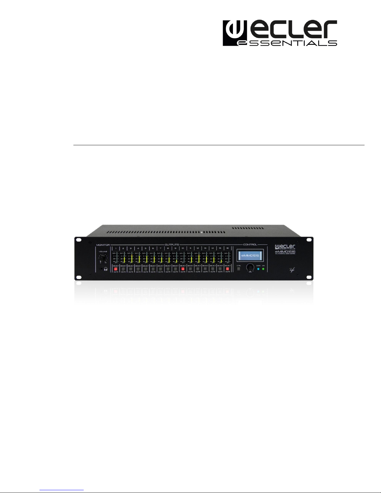
The eMIMO1616 is a digital audio matrix featuring multiple inputs and outputs,
which is programmable via an embedded web-server application (controlled via a
standard web browser in Windows / MacOS, etc.) or via remote control through
physical wall-mounted panels, messaging consoles (paging) and applications for
mobile devices (Android, iOS).
Main features include:
4 local inputs for stereo audio, compatible with line levels and gain
adjustment from -6 to +16 dB. 2xRCA and Euroblock connectors on rear
panel (INPUT 1 to INPUT 4)
4 local inputs for mono audio, compatible with microphone and line levels,
gain adjustment from 0 to +50 dB. Euroblock connectors on rear panel
(INPUT 5 to INPUT 8)
8 remote inputs for balanced mono audio, compatible with line level.
Available on RJ45 connectors on rear panel (REMOTE INPUT 1 to REMOTE
INPUT 8)
2 local PAGER (A and B) inputs, compatible with eMPAGE messaging
consoles, receiving the signal from its microphone. RJ45 connectors on rear
panel (INPUT 7 to INPUT 8)
16 audio output channels (zone output), line level independently
configurable and balanced, such as:
oMono outputs (1 channel per output)
oStereo outputs (2 channels per output, natural pairs, 1-2, 3-4, 5-6,
etc.)
1 audio output for headphones for the MONITOR function for output zones,
mini-jack connector and volume control on front panel.

7
8 REMOTE ports for connecting eMCONTROL1 wall format remote digital
panels. RJ45 connectors on rear panel.
Ethernet interface with RJ45 connector, for programming and remote
control of the unit via integrated web application (embedded web server)
and/or TP-NET protocol for third-party integration.
RS-232 interface with DB9 connector, for remote control of the unit via TP-
NET protocol for third-party integration.
MUTE port for muting one or more output zones (up to 16 available) via
closing of external potential-free contact.
16 sets of VU meter and SELECT/MUTE keys on front panel for the control
and visualisation of output signals (zones) from the front panel.
LCD screen, CONTROL key and rotary digital control (encoder) for the
control of unit zone outputs from the front panel.
DATA indicators (connection via external client devices) and ON (switched
on) on the front panel.
Processing available for inputs::
o3-band EQ adjustment via BASS-MID-TREBLE controls.
oVolume adjustment and MUTE control.
oPhase inversion
oNoise gate (available for INPUT 5 to INPUT 8 local inputs)
oVariable frequency high-pass filter (available for INPUT 5 to INPUT 8
local inputs)
oAudio over audio priority function, with two levels: inputs 5 to 8
MIC/LINE can fade (or mute fully) the sound content present
(program audio) in specific output zones, enabling the broadcast of
emergency announcements, warnings, etc. Each of these inputs can
perform this function with priority 1 (superior) or 2 (inferior). The
activation modes for the priority function can be:
DUCKER: via audio signal detection; on reception of a valid
signal and while the input in question continues. Available on
local inputs 5 to 8.
PAGER: via selection of the output zones, pressing the PAGE
key, and real-time voice-over from eMPAGE messaging
consoles. Chime available as an alert prior to message voice-
over, on activating PAGE function. Available on local inputs 7
and 8 (PAGER A and PAGER B, respectively)

8
Processing available for outputs:
oMono mode (outputs managed individually) or stereo mode (outputs
managed in natural pairs): 1-2, 3-4, etc.). Automatic handling of
mono or stereo audio sources routed towards mono or stereo
outputs.
oSelection of program source (local or remote audio inputs)
o3-band EQ adjustment via BASS-MID-TREBLE controls.
oVolume adjustment and MUTE control.
oLimitation on available output volume range (minimum and
maximum levels) for end user, from any method of control
(eMCONTROL1 panels, client pilot application, etc.)
oPhase inversion
oEnablement for muting via MUTE port on rear panel (via closing of
external contact)
Programming and control as Administrator (admin) via the embedded
web application, using a computer, tablet or mobile device, and a standard
web browser (without the installation of dedicated software)
Remote control for end users via:
oFront control panel, with programmable access restrictions
oeMCONTROL1 physical wall panels
oeMPAGE (paging) messaging consoles
oeMIMO pilot application, available for iOS and Android devices
oStandard web browsers, via computers, tablets, etc.
Note: from the unit's embedded web application, the admin user can set
restrictions on controls and adjustments available from the physical wall panels
(eMCONTROL1) and messaging consoles (eMPAGE) for the end user, together with
user accounts and the graphic control and adjustment panels that the end users
can use via the eMIMO pilot and web applications.

9
5. INSTALLATION AND CONNECTION
5.1. Location, assembly and ventilation
The eMIMO1616 has been specially designed for incorporation within a 19" rack,
occupying 2 U’s.
It is very important that, as a heat generating element, the unit is not completely
enclosed or exposed to extreme temperatures. The passage of fresh air through the
ventilation holes on the chassis should be ensured, by leaving at least 1 U free
between each unit and those installed above and below on the rack.
If the installation includes various pieces of equipment on the same rack, or is
within a cabinet with doors, then the provision of upward forced ventilation,
through the fitting of fans on the lower and upper extremes, is highly
recommended. The upward ventilation flow will improve the dissipation of heat
generated within.
5.2. Connection to the mains supply and switching on
The eMIMO1616 is powered by an AC voltage of 90 to 264V at 47 to 63Hz. The unit
features an overdimensioned power supply unit capable of adapting to the supply
voltage in any country in the world without the need for adjustment.
The on/off switch for the unit is on the rear panel, next to the IEC mains connector.
On the front panel there is an LED ON indicator, which is lit when the unit is
functioning.
Do not allow the supply cable to become entwined or run parallel to the shielded
cables carrying the audio signal, as this could cause buzzing.

10
5.3. Local audio input connections
The eMIMO1616 has a rear panel with 8 local audio inputs, with the following
connection types available:
INPUT 1 to INPUT 4: unbalanced stereo line-level signals, with double
connector format (RCA and Euroblock). Use either of the connectors, based
on the type of cable available between the sound source and the
eMIMO1616 unit:
oDouble RCA connector: connect the stereo sound source directly (CD
players, Smart phones, radio tuners, streaming players, etc.) via a
cable that delivers the left (L) channels and right (R) channels to the
white and red RCA connectors on the unit, respectively.
oEuroblock connector, 3 contacts; connect the stereo sound source in
this way:
Left channel > L Terminal
Right channel > R Terminal
Earth > Terminal
INPUT 5 to INPUT 8: mono balanced microphone or line signals, with
Euroblock 3-contact connector:
oHot or direct signal > + Terminal
oCold or inverted signal > −Terminal
oEarth > Terminal
11
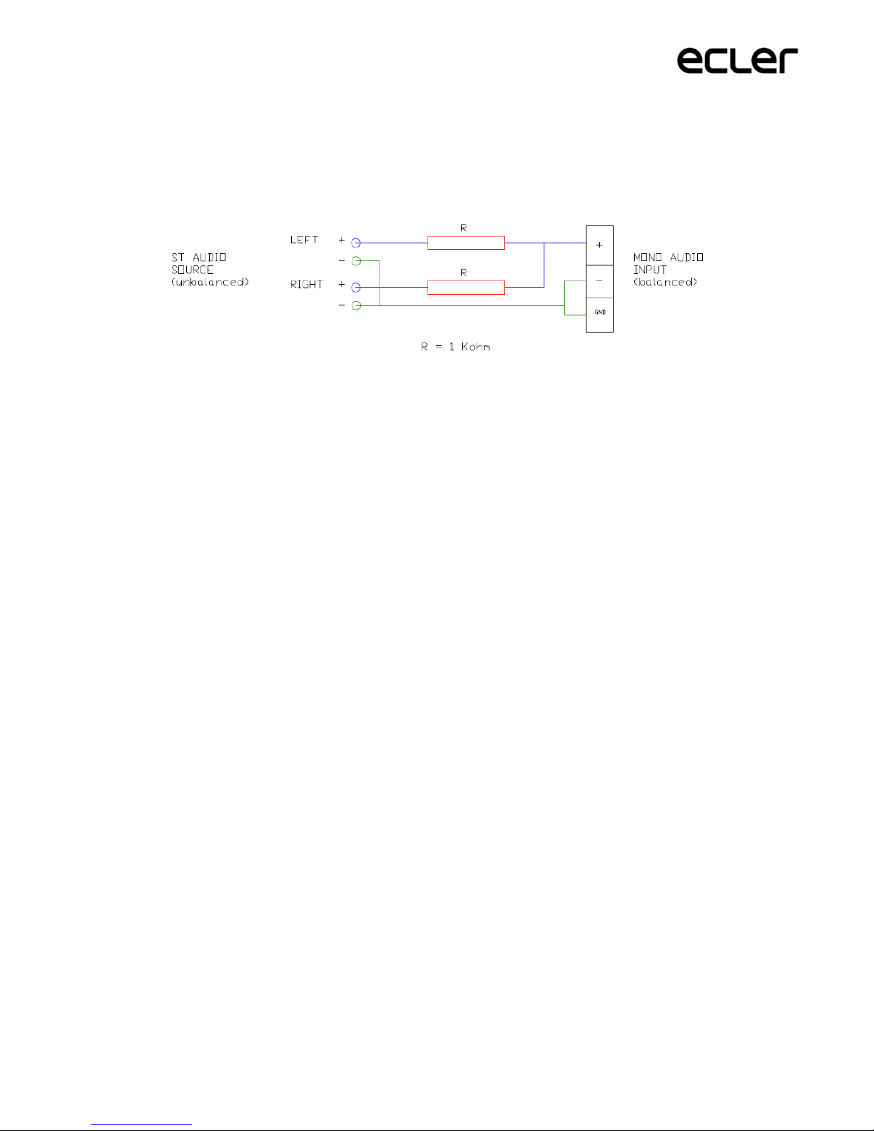
Note: if the sound source is stereo, and you want to connect it to one of the IN5 to
IN8 local mono balanced inputs on the eMIMO1616 unit, you can do it via the
following stereo to mono conversion, simply by using a pair of external resistors:
On the rear panel of the unit there is a PHANTOM ON/OFF switch, which allows the
provision of a phantom power supply to inputs 5 to 8 for use with microphones
(usually condenser microphones).
In addition, there are 2 connection ports called PAGER A and PAGER B, with
INPUT 7 and INPUT 8 audio inputs (respectively) duplicated for use with
PAGER priority modules. These ports receive audio signals from eMPAGE
messaging consoles. A standard (crossover) CAT5 or higher cable, with an
RJ45 connector on each end, connects a messaging console point to point to
either of ports A or B on the unit, through which the remote DC supply for
the messaging console, control data, and balanced audio from the
messaging console microphone can be transmitted. The maximum number
of messaging consoles allowed is 2: one connected to the PAGER A port and
the other to the PAGER B port.
Once the physical connections for the various audio inputs have been made, it will
be necessary to adjust the GAIN control for each of them, in order to obtain a signal
of maximum intensity and maximum signal / noise ratio, so that they can be
correctly employed as sound sources for the installation. To that end it is necessary
to maximise the volume controls for the audio players, before adjusting the gain on
the eMIMO1616 unit. Use the level indicators on the front of the unit (physical VU
meters), and the virtual level indicators (on-screen VU meters) from the web
application in order to correctly adjust the gain, seeking to obtain signal peaks for
the zone of close to 0 dB (orange zone on the virtual VU meters) with peaks above
this (“red” zone, saturation or clipping) being the exception.
12
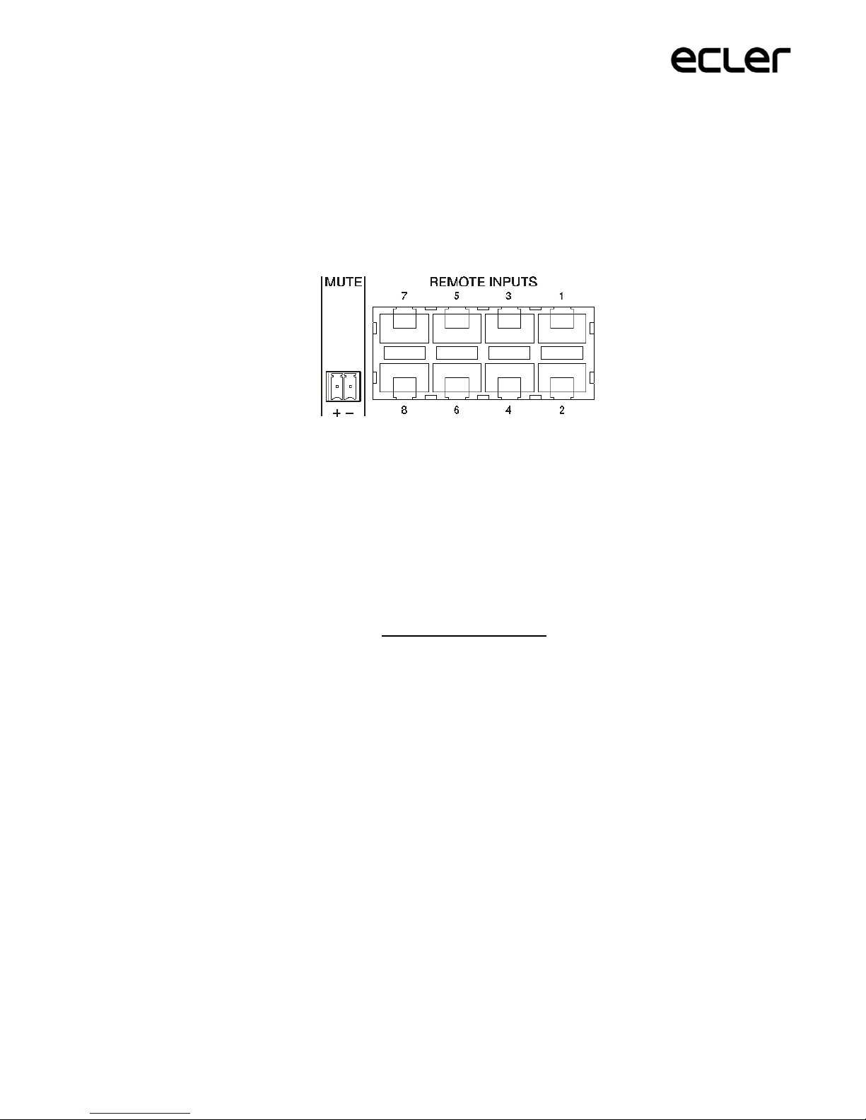
5.4. Remote audio input connections
The eMIMO1616 has 8 control ports (REMOTE INPUTS) with RJ45 connector, for
the connection of eMCONTROL1 remote control panels. Each of these ports, in
addition to providing the DC power supply and digital communication bus for the
remote panels, has a balanced mono audio input with line level, taken as a remote
input for the eMIMO1616 unit. It is thus possible to increase the number of audio
inputs for the unit using these 8 remote inputs, in addition to the 8 local inputs
available via audio connectors on the rear panel of the matrix.
13
The connection of a balanced mono audio signal to a REMOTE port on the
eMIMO1616 matrix is made in the following way:
Hot or direct signal > Terminal 8 on the RJ45 connector
Cold or inverted signal > Terminal 7 on the RJ45 connector
Earth > Terminal 6 on the RJ45 connector
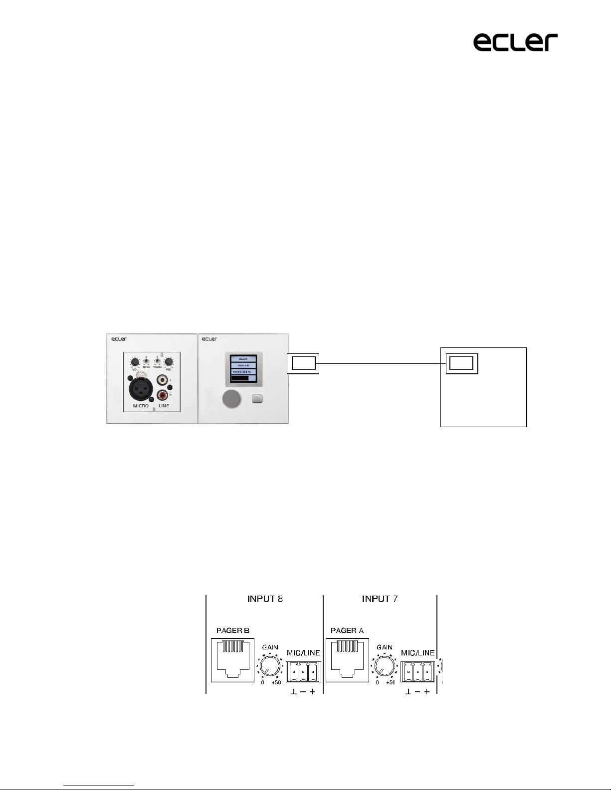
In the event of using an eMCONTROL1 remote panel to control a zone of the
installation, the eMCONTROL1 panel itself has an internal connector to receive the
audio signal from an adjacent, complementary panel, such as the WPaMIX-T, on the
pair from the example below. This configuration type is ideal for remote control of
the zone and audio from the zone itself: a single CAT5 standard cable is connected
between the eMCONTROL1 panel and a REMOTE port on the eMIMO1616 unit, to
provide the DC power supply, transmit digital control data, and send remote audio
signals from a physical input on the eMCONTROL1 complementary panel to the
eMIMO1616 unit.
5.5. PAGER A, PAGER B connections and priority PAGER / DUCKER
modules
In the local inputs section on the rear panel there are 2 ports called PAGER A and
PAGER B, with audio inputs internally matching INPUT 7 and INPUT 8
(respectively).
eMIMO1616
REMOTE ports
RJ45 connector on
eMCONTROL1
CAT5
Pair of wall panels, on which eMCONTROL1 (right) receives the balanced
audio from its complementary panel, WpaMIX-T (left)

14
The PAGER ports are used for point to point connection to 2 eMPAGE messaging
consoles, through which it is possible to perform functions such as real-time voice
calls (paging) to output zones within the installation, using a priority module on
the eMIMO1616 unit which fades or fully mutes the sound content of the existing
program in those zones at the time of the action.
A standard (crossover) CAT5 or higher cable, with an RJ45 connector on each end,
connects a messaging console point to point to either of ports A or B on the unit,
through which the remote DC supply for the console, control data, and balanced
audio from the messaging console microphone can be transmitted.
A maximum of 2 consoles is allowed; one connected to the PAGER A port, and the
other to the PAGER B port, with each one using a PAGER priority module on the
eMIMO1616 unit.
Note: it is it not possible to perform the following connections simultaneously,
and the connections listed below are mutually exclusive:
a messaging console to the PAGER A port + an audio signal to the INPUT7
Euroblock connector
a messaging console to the PAGER A port + an audio signal to the INPUT7
Euroblock connector
The total number of PAGER (to messaging console) or DUCKER (without
messaging console) priority modules for the eMIMO1616 is 4, assignable to the
local inputs 5 to 8. These 4 modules may be activated or deactivated, and each of
them may use one of the 2 available priority levels, so that the signals with greater
priority will fade the program signal selected in the destination zone, in addition to
the signals of lesser priority sent to these zones, if there are any, at the time when
the maximum priority module is activated.
See the eMIMO1616 web application manual to find out more about programming
the PAGER / DUCKER priority modules.
15
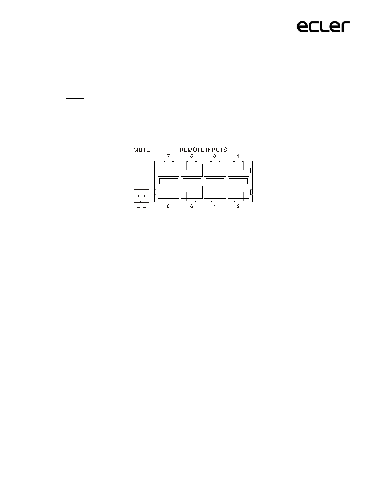
5.6. REMOTE INPUTS 1 to 8 connections
On the eMIMO1616 rear panel there are 8 control ports, REMOTE INPUTS 1 to 8,
which are enabled for the connection of eMCONTROL1 zone control wall panels.
Each port has an RJ45 connector, and each eMCONTROL1 panel also has an RJ45
connector, such that the physical connection between a remote panel and a
REMOTE port on the eMIMO1616 unit can be made, point to point, via a CAT5
standard or higher (crossover) cable.
This physical connection provides a DC power supply to the remote panel from the
eMIMO1616 unit, and establishes a digital communication bus between the two
pieces of equipment. It also allows the reception of balanced mono audio from a
potential remote sound source (connected on the side of the control panel) on the
eMIMO1616 unit.
The wall control panels are configured by the Administrator user via the
eMIMO1616 web application(see web application manual for the eMIMO1616), so
that it is possible to fully disable them, or enable them to function as user controls
for an installation zone, including all or some of the following functions:
Selection of sound source (program audio), from a customised list for each
panel that includes some local sources and/or the remote source itself.
Volume adjustment (with a maximum and minimum adjustment margin)
and mute control
Equalisation adjustment, with 3-band EQ (BASS-MID-TREBLE).
Alternatively, these inputs may receive, exclusively, a balanced mono signal via the
RJ45 connector, while respecting the corresponding assignation of pins (see
section 3.4):
Hot or direct signal > Terminal 8 on the RJ45 connector
Cold or inverted signal > Terminal 7 on the RJ45 connector
Earth > Terminal 6 on the RJ45 connector
16
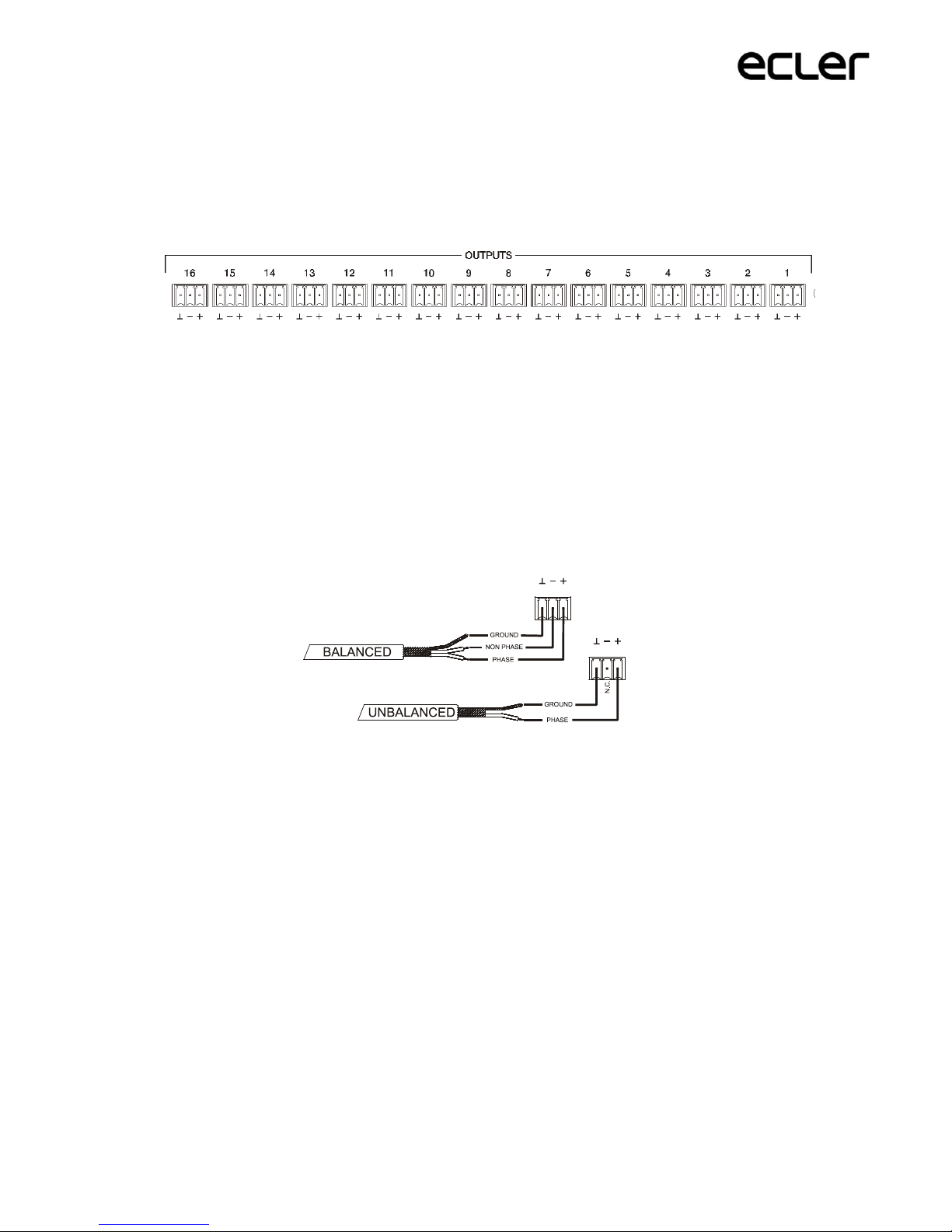
5.7. Audio output connections
The eMIMO1616 has16 audio output channels (zone outputs), with independently
configurable balanced line, such as:
mono outputs (1 channel per output)
stereo outputs (2 channels per output, natural pairs, 1-2, 3-4, 5-6, etc.)
Each output has a 3-contact Euroblock connector,
Hot or direct signal > + Terminal
Cold or inverted signal > −Terminal
Earth > Terminal
In the event of connecting an output channel to an amplifier or audio device with
balanced input, it is recommended to connect terminals +, − and point to point
between the two units. In the event of connecting an output channel to an amplifier
or device with an unbalanced audio input, do not connect the − terminal.
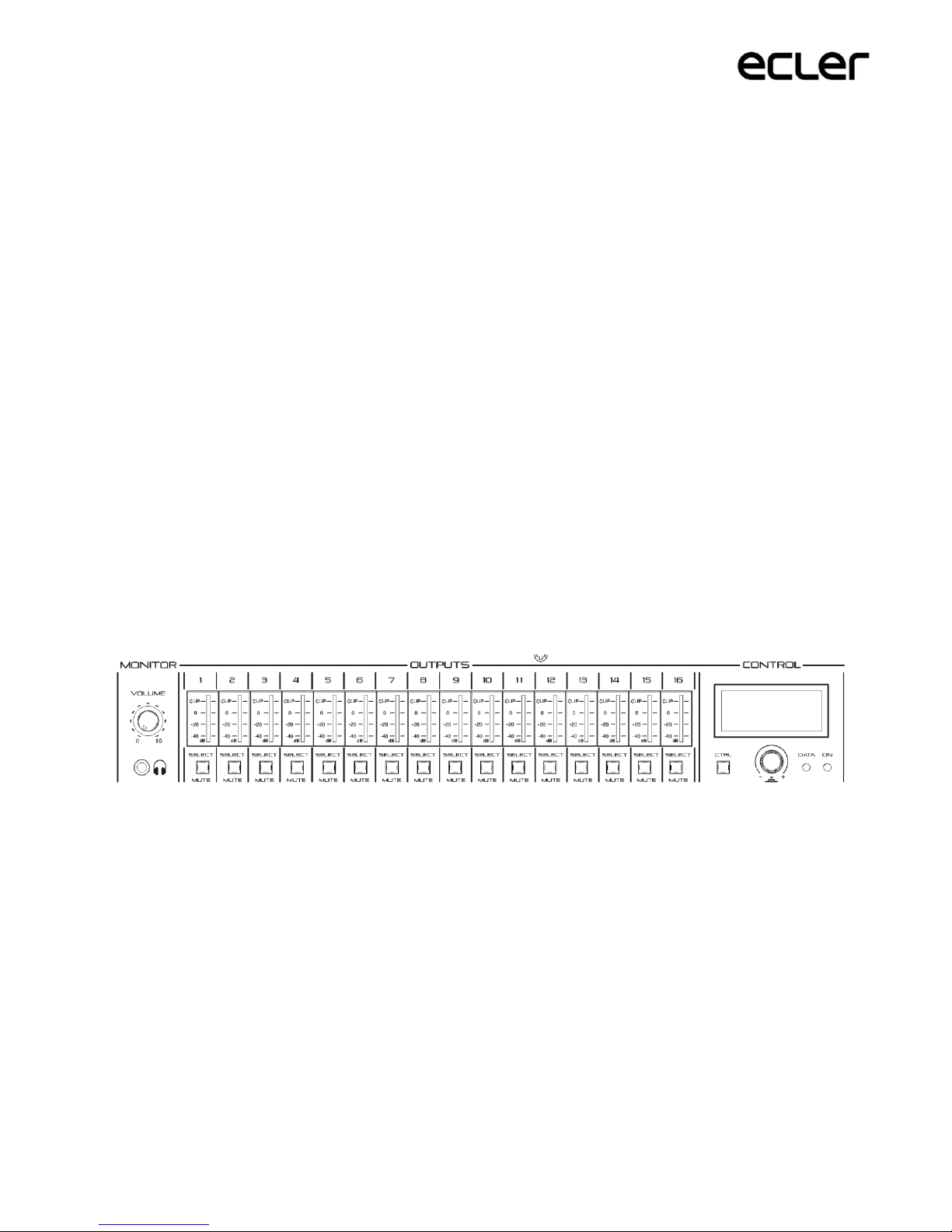
MONITOR output (marked with a headphones symbol): 3.5mm stereo mini-jack
connector with rotary level control to listen via headphones. It is particularly
useful for listening to output signals from the unit without disturbing its normal
operation. The selection of the signal to listen to is made via the front panel, simply
by pressing the “select” button for the zone you wish to monitor. The volume
control for the headphones signal is after the volume control for the zone, so that
the volume of the zone, or whether it is in MUTE, will have to be taken into
account.

17
5.8. ETHERNET and RS-232 ports for programming and control
The RJ45 ETHERNET connector on the rear panel allows the connection of the unit
to an Ethernet network, either directly to a computer or to another device with an
Ethernet interface, point to point. This connection enables, within a local network,
the following:
The Programming and overall management of the eMIMO1616 unit via the
embedded web application and a standard web browser running on a
computer, a tablet, etc.
The connection of client devices for the end user in installation zones via
the eMIMO pilot application, which is compatible with Android and iOS, or
via standard web browsers running on computers, tablets, etc.
The connection of third-party equipment for integration within control
systems (Crestron®, Extron®, AMX®, Vity®, Medialon®, etc., brands
registered by their manufacturers), using the TP-NET protocol embedded in
the eMIMO1616. See the TP-NET protocol manual for further information.
The DB9 RS-232 connector on the rear panel allows the connection of the unit
point to point to a computer or other control device. This connection exclusively
uses the integration via series port with third-party equipment and control
systems (Crestron®, Extron®, AMX®, Vity®, Medialon®, etc., brands registered
by their manufacturers), using the TP-NET protocol embedded in the eMIMO1616.
See the TP-NET protocol manual for further information.
The parameters necessary for a correct series connection are the following:
Baud rate: 115200 (fixed, no autonegotiation)
Data bits: 8
Parity: None
Stop bits: 1
Flow control: None

18
5.9. MUTE port
The eMIMO1616 has a control input, or MUTE port, on the rear panel, which allows
the enabling / disabling of mute for audio outputs (zones) from the unit via a
button, relay or the closing of an external potential-free contact.
The allocation of outputs affected by the MUTE port is set via the eMIMO1616 web
application. See the eMIMO1616 web application manual for further information.
6. CONFIGURATION AND CONTROL
6.1. Configuration via embedded web application
Once the physical connections have been made, the eMIMO1616 must be
configured via the embedded web application, from a computer, tablet, or similar
device on which it is possible to open a standard web browser, connected to the IP
address of the unit (by default 192.168.0.100, but may be changed). This task is
reserved exclusively for the system installer or Administrator, who must be
identified by “admin” user credentials:
See the eMIMO1616 web application manual for full information regarding
configuration of the unit.

19
Note: the eMIMO1616 has an information screen which is activated by pushing and
holding simultaneously (>3 seconds) the CTRL key and the encoder on the front
panel:
The screen shows the following information:
Firmware version being used by the unit
NAME: name of the eMIMO1616 unit
Network connection parameters: IP address, subnet mask and network
gateway
Bank1: memory bank in use (1 or 2). Useful information for the detection of
and solution for various problems with the unit
Admin: number of admin users connected to the unit (0 or 1)
Users: numbers of client users, via the eMIMO pilot application or web
browsers (0 to 20)
The main parameters, settings and functions which are accessible on the
eMIMO1616 from its web application are:
General configuration; unit name, network parameters, recording and
recovery of projects (overall equipment configuration), start mode,
firmware updates, default parameter reset, connection status, etc.
Management of user accounts, which will allow access to external clients
(end users) via the eMIMO pilot application or web browsers: names,
passwords and enabled / disabled status
Front panel parameters:
oadjustments to LCD screen: brightness, contrast, stand-by mode
ooverall access / blocking (for all front controls)
oindividual access / blocking for specific controls, and for specific
output zones. It is possible to allow access to the settings for some
zones and block them for others, or even decide which parameters
are accessible for each of them: volume adjustment and MUTE
and/or selection of sound source and/or equalisation via 3-band EQ
(BASS-MID-TREBLE)
Local and remote audio input parameters; names, polarity, volume, MUTE,
equalisation via 3-band EQ (BASS-MID-TREBLE), noise gate, high-pass filter,
etc.
Parameters for audio output (zones): names, mono / stereo mode, polarity,
selection of sound source, volume, accessible volume range for end users
(maximum and minimum levels), MUTE, equalisation via 3-band EQ (BASS-
MID-TREBLE), noise gate, high-pass filter, effect of MUTE port activation
(closing of external contact), etc.
20
Configuration of the 4 PAGER / DUCKER priority modules (with eMPAGE
messaging consoles / activated via audio level detection on the input in
question, respectively)
Configuration of the eMCONTROL1 physical control panels connected to the
eMIMO1616 unit; connection status, enabled / disabled status; zone under
control, enabled functions (volume adjustment and MUTE and/or selection
or sound source and/or equalisation via 3-band EQ (BASS-MID-TREBLE),
etc.
Creation, edition and configuration of the pilot panels, accessible from
external devices via the eMIMO pilot application or web browsers: public or
private panel (accessible only for specific users), enabled / disabled status,
zone under control, enabled functions (volume adjustment and MUTE
and/or selection or sound source and/or equalisation via 3-band EQ (BASS-
MID-TREBLE), graphical appearance (control types, slider or rotary, control
colours, texts and background), etc.
6.2. Front panel control
Using the physical controls on the front panel of the eMIMO1616 it is possible to
make adjustments to the various output zones from the unit. The settings available
for the various zones will be those that the admin user enabled via the web
application, and may range from blocking the entire front panel to complete
freedom to control all zones (volume adjustment, source selection and equalisation
adjustment), or the total or partial blocking of some of them.
Pressing a SELECT key corresponding to one of the outputs on the unit allows it to
be controlled via the CTRL key, the encoder and the LCD screen on the right of the
front panel. In addition, the LED indicator on the SELECT key pressed will flash
with a fixed rhythm (long off, short on), indicating that the output has been
selected for control. After a few seconds without changing the front controls, in
other words, without making any adjustments, the key will stop flashing.
Table of contents
Popular Matrix Switcher manuals by other brands


Kramer
Kramer Sierra Pro XL 1616V5 Specifications

Matrix Switch Corporation
Matrix Switch Corporation MSC-XV3248 product manual

NTI
NTI VEEMUX SM X 15V-LC Series Installation and operation manual

ATEN
ATEN VanCryst VM0404H user manual

Digitus
Digitus DC-48101 user manual

BeingHD
BeingHD TOUCH MANAGER Series user manual