Eco Pacific AussiVent Manual

P a g e | 1
Version10- March 2017 Eco Pacific Pty Ltd
IOS MANUAL
Installation, Operation, and Service Instructions
Fresh Filtered Air Ventilators with Efficient Heat/Cool Recovery from Indoor Air
Models: AussiVent / EcoVent/ FreshVent
Please read these instructions prior to installation
Manufactured by Eco Pacific Pty. Ltd., Australia
www.ecopacific.com.au
Email: sales@ecopacific.com.au
Tel: +61-3-9706 6228 or 1300ecopac

P a g e | 2
Version10- March 2017 Eco Pacific Pty Ltd
Fresh Filtered Air Heat Recovery Ventilator (HRV)
1. INTRODUCTION
The purpose of this guide is to give the installer and service / maintenance personnel a
quick reference to general information they must know when installing the ECO PACIFIC
HRV.
This publication is designed to help the installer. The guide consists of:
•Overview of HRV;
•The dealer / contractor’s responsibilities;
•Installation procedures, and
•Warranty details.
1.1 OVERVIEW OF OUR HRV
This Eco Pacific Heat Recovery Ventilator innovation substantially improves the quality of
indoor air, which is increasingly becoming an issue in densely populated and polluted cities
of India, China, Brazil, Thailand, South Korea, Hong Kong, Malaysia, Vietnam, and many
other fast developing countries.
The HRV extracts the contaminated air inside rooms and introduces outside fresh air to the
rooms at around the same temperature as the air inside the rooms. This enhances the
rooms air quality and reduces the build up of gases such as CO2and unpleasant smells, to
a level that promotes Personal Well Being.
The HRV system employs energy transfer between outgoing and incoming air, utilising a
counter flow Heat Exchanger made of anti-rusting marine grade aluminium alloy, and does
not make use of or replace a traditional air conditioning system.
The heat exchanger transfers the heat (in winter) or the coolness (in summer) of the
expelled indoor air to the incoming fresh air, due to temperature difference. With an energy
recovery effectiveness of up to 85%, the HRV delivers fresh filtered air at near room
temperatures in all seasons irrespective of outdoor temperatures. The HRV operation
assumes that the indoor space is air-conditioned by an existing heating or cooling device,
which usually only recycles the same indoor air within closed doors and windows. There is
no active heating or cooling device fitted in this HRV, but rather a passive Heat Exchanger
that exchanges sensible heat energy between the incoming and outgoing air streams. The
standard HRV operates through a normal 240 V, 10 Amp switch, like a normal ceiling fan.
The incoming outdoor air passes through an externally mounted filter box. The filter box is
connected through a duct to the HRV mounted either on a wall, in a roof cavity, or on the
roof.
Optional: The HRV can also be operated by an Optional Wall Controller fitted with sensors
for either CO2levels of the indoor air, any motions surrounding the wall controller, or
blockage of the outdoor air filter. If the CO2of the room reaches harmful levels and the
ventilator is in auto-off mode, the sensor will automatically activate the ventilator to provide
fresh filtered air at near room temperature. If the filter is blocked, the LED on the On-Off
switch or on the Wall Controller will turn Red to indicate that the filter needs to be cleaned.
A house fitted with this HRV will not require open doors or windows, and will introduce fresh
filtered atmospheric air in the living space at near room temperatures, and assist in keeping
the house clean and hygienic, so as to enhance a Healthy Well Being effect in the house.

P a g e | 3
Version10- March 2017 Eco Pacific Pty Ltd
Standard heating and cooling appliances fitted in houses often recycle the same bad air
that residents inhale and exhale, including the unhealthy emissions coming from kitchens
and toilets, compelling the residents to seriously compromise their health. Constant
exposure to bad air for a long time can lead to lung disorders, and can cause itching of the
throat and eyes, laziness, and poor concentration of mind. The HRV addresses these
indoor air quality issues.
The Fresh Air Ventilator with heat recovery is highly recommended for use in Cool
Rooms, Residential Apartments, Health Clinics, Hospitals, Hotels, Schools, Aged
Care Facilities, and Offices, just to name a few.
All enquiries related to this innovation should be addressed to Eco Pacific Pty Ltd at
1.2 HEAT EXCHANGER
The Eco Pacific Heat Exchanger has been tested to ASHRAE 84 standard for Air -To - Air
Heat/ Energy Exchange, by Australia’s NATA accredited test lab, VIPAC Engineers and
Scientists, for thermal performance and pressure drop (Report ref.30S-15-0158-TRP-
392476-1-2016).
1.3 MODELS AND THEIR DISTINCTIONS
There are three models which all utilise a common thermal transfer process. The fresh air
ventilator is fitted with a Heat Exchanger in the centre of its cabinet, and is connected with
an external filter box to introduce atmospheric air through a duct sized to the installation.
The Filter Box remains accessible to the user for filter service, and filters outdoor polluted
air and introduces it in the living space after passing through the Heat Exchanger which
transfers heat or cool from the higher temperature stream to the lower temperature stream
coming from opposite direction. The HRV removes the contaminated air of the room by
exhausting this air through the Heat Exchanger that recovers the heat or cool of the
contaminated indoor air, and transfers it to the incoming fresh filtered air. The HRV is able
to deliver the fresh filtered air at near room temperature in all seasons irrespective of the
outdoor air temperature.
The 3 models of HRV are;
1. AussiVent designed to provide fresh filtered air with heat recovery to homes.
Two sizes are available, namely AV80 and AV120 that are both suitable from 2 bed
room to 4 bed room apartments and houses accommodating up to 10 people.

P a g e | 4
Version10- March 2017 Eco Pacific Pty Ltd
2. EcoVent designed to provide fresh filtered air with heat recovery to offices, schools,
and hospitals.
Two sizes are available, namely AV80 and AV120.
3. FreshVent designed to provide Ethylene gas extraction from cool rooms and cold
storages and substitute with fresh filtered air and heat recovery.
Two sizes are available, namely FV80 and FV120.
Illustration 1- Physical appearance of the three models with their dedicated controls
1.4 FILTER BOX
The Filter Box is the same for all the models. The filter cassette can be customised to
specific applications.
The standard filter comes with the following characteristics;
•Material: Washable polyester wool
•Grade: G4-18 mm washable polyester wool
•Rated air velocity: 1 m/s
•Clean air resistance: 40 - 50 Pa
•Nominal thickness: 20 mm
•Final Air resistance: 200 Pa
•Maximum average temperature: 120 Deg C
•Average dust arrestance: 90% to dust test #4.
•Colour: White

P a g e | 5
Version10- March 2017 Eco Pacific Pty Ltd
Below are the illustrations of Filter Boxes with 6 inch and 3 inch outlets for duct connections
to the HRV cabinet.
Illustration 2 - Air Filter Boxes with 6 inch and 3 inch outlets
1.5 WALL CONTROLLERS
The standard Wall Controller is a 240 V switch fitted with a filter sensor light. If the filter is
blocked, the light will turn Red. The Optional Wall Controller is fitted with C02sensor,
motion sensor, and filter sensor, and operates the EcoVent model of the fresh air HRV.
Illustration 3: Standard Wall Controller (left).
Illustration 4: Optional Wall Controller for EcoVent CO2sensor (right).
1.6 AIR FLOWS
AV80, EV80, and FV80 provide air flows of 80 l/s at 100 Pa external static pressure (ESP).
AV120, EV120, and FV120 provide air flows of 120 l/s at 100 Pa ESP.
Note the Filter Sensor is fitted to the standard switch to operate the AussiVent and
FreshVent models, however the EcoVent is operated by an Optional Wall Controller.
1.7 OPTIONS
The Wall Controller can be fitted with;
CO2sensor to measure the Carbon dioxide level in the room air and auto-activate the
ventilator with low, medium and high level indicators.
PIR (Photo Infrared) sensor to register any motion surrounding the Wall Controller and
auto-activate the ventilator as may be required in schools, board rooms, hospitals, and
clinics etc.
Filter Sensor to measure when the filter is above 80% blockage, and turns the LED on the
Wall Controller to Red to alert the user to clean the filter.

P a g e | 6
Version10- March 2017 Eco Pacific Pty Ltd
All the PCB electronics of the Optional Wall Controller are fitted into a fire resistant heavy
duty ABS plastic enclosure.
2 CONTRACTOR’S RESPONSIBILITIES
Application
The manufacturer supplying the HRV relies on the Contractor to apply and install the unit so
that it will provide a satisfactory operation. The total system must satisfy the customer’s
needs and operate within the published limits of the HRV.
Installation
The Contractor should ensure HRV units are installed in accordance with the procedures
outlined in this publication, as well as abiding by the HRV’s specific installation
requirements.
Service
If a problem arises, the Contractor is to ensure a qualified repair person resolves the
customer’s difficulties.
2.1 EQUIPMENT INSPECTION
CONDITION OF SALE FOR WARRANTY -
The HRV's are sold through a Supplier Dealer Network with the following responsibilities
entrusted to them;
•Do not install the unit without reading the instructions.
•The unit should be inspected on delivery for possible internal and or external damage
incurred during transport and handling. If any damage is detected, it should be noted
on the delivery docket with photo evidence attached and be sent to the local agent /
dealer. The damage should be claimed within three days from inspection.
•The manufacturer supplying the HRV relies on the dealer / contractor / installer to install
it satisfactorily in accordance with these instructions.
•The installation should allow satisfactory operation of the HRV to provide fresh filtered
air to the indoor environment with the filter box fitted outside in fresh air.
•Ensure that the filter of the filter-box is easily accessible to the user for routine cleaning,
service, and maintenance.
•It is the responsibility of the dealer / contractor to ensure that a suitably qualified and
well trained person is engaged for installation and service of these HRV's.
•IMPORTANT: ensure the electric cord suits local voltage. Do not operate the HRV if
voltages are different.
•Note: If the HRV is not installed and serviced according to these instructions, the
manufacturer will not be able to meet the warranty conditions provided with the HRV.
3 INSTALLATION
3.1 SAFETY
Note: This HRV must only be installed by a fully qualified and licensed electrician.
These HRV's shall be installed in accordance with;
•LOCAL HEALTH AND SAFETY REGULATIONS
•Local plumbing and drainage codes
•Local wiring codes and rules for electrical connections (refer to HRV electrical wiring
requirement shown on specification plate on the cabinet).

P a g e | 7
Version10- March 2017 Eco Pacific Pty Ltd
These HRV's are designed for installation on a hard surface of an external wall, in a loft, in
a roof space, under the floor, in a basement, or on the roof. For maximum effectiveness,
the HRV should be installed halfway between the Return Air Grille and the Supply Air Grille.
3.2 PHYSICAL SPECS
Dimensions of models;
Length collar to collar: 760 mm (AV/EV) 815 mm (FV)
Height: 510 mm
Width: 240 mm
Weight excl. wall brackets: 12.5 kg (EV) 12 kg (AV/FV)
Note: Any ducting and vents for installation are not supplied with the HRV's. Insulated
Flexi/solid ducts are recommended for the Return Air from indoor to the unit.
Inlet outlet collar sizes for ducting
AussiVent and EcoVent models AV80, AV120, EV80, and EV120 are fitted with 6 inch
collars for fresh air intake, fresh air supply, indoor air intake, and indoor air exhaust.
Fresh Vent models FV80 and FV120 are fitted all with 3 inch outlets suitable for cool room
applications.
All the above models are supplied in weather resistant UV stabilised ABS plastic, rugged
enough for long endurance.
Electricians please follow the following three steps to install the HRV on the wall using the
steel brackets and bolts shown below through three illustrations.
Wall brackets- Illustration 5
Fasten the joiner in the middle to the two wall brackets as shown above.

P a g e | 8
Version10- March 2017 Eco Pacific Pty Ltd
Use the M5 bolts 2 each side on the wall brackets
Put the HRV on the bracket, slide it through and fasten it on to the brackets using two
M5 bolts each side threading from the bottom into the nut-serts of the HRV.

P a g e | 9
Version10- March 2017 Eco Pacific Pty Ltd
3.3 FILTER BOX INSTALLATION
A Filter Box as a standard pre-filter is to be installed with every ventilator and has to be
located outside to take fresh air. This Filter Box should be positioned at least one meter,
but not more than 7 meters, away from the exhaust outlet of the HRV for smooth fresh air
inflow. The Filter Box is fitted with a G4 polyester filter cassette that can be cleaned by
removing the grille cover then the filter. Another filter box with HEPA type filter down stream
can also be added for further fine cleaning as required. This may compromise the air flow.
The standard filter is washable and can be vacuumed to keep it clean and clear of any dust
and debris.
Optional filters to meet specific requirement can be sourced from any filter supplier.
Note: Exhaust air outlet has to be away from the fresh air intake to avoid air mixing and
should be wire-meshed for protection from birds and insects. The indoor air inlet should
also be fitted with a wire mesh filter inside the grille to protect the heat exchanger from dirt
scaling and insects and should be cleaned monthly.
3.4 SERVICE CLEARANCES
It is recommended that a clearance of 600 mm be provided at each end of the HRV where
the duct collars are fitted, and 750 mm at one side for easy service of the HRV.
The ducting must not intrude on these clearances for servicing.
Illustration-6: wall installation of HRV with Filter Box below
3.5 IN ROOF AND ON ROOF INSTALLATION
The HRV's can be installed alone or can be added to the existing air handling units or
ducted heaters or coolers, as a fresh air supplement at the design and sizing stage or as a
retrofit. A qualified air-conditioning installation contractor or mechanic should be consulted
on sizing the model and ducting. The HRV should be connected downstream to the existing
ducted heating cooling appliance. The ducting should be connected with return to return
and supply to supply of both- the HRV and the heating /cooling appliance. The installer has
to make sure the ducts are harnessed tight onto the collars using duct tapes.

P a g e | 10
Version10- March 2017 Eco Pacific Pty Ltd
Illustration 7: In Roof or On Roof installation
3.6 COLD ROOM INSTALLATION
Cold rooms are normally fitted with air handling units that can create the low temperatures
required to preserve fruits and vegetables. Ripening of fresh Produce can create pungent
gases such as ethylene that aggravates the ripening process, occasionally culminating with
rotting of the Produce. The FreshVent HRV can remove the ethylene and bring fresh
filtered air into the cold room to slow down the ripening process. The out-door air in the
process condenses water that requires the drainage discharge that is fitted to the FreshVent
units.
Refer to the separate Fresh Vent Installation, Start Up and Service Instruction Manual
for more detailed information on the FreshVent HRV.
Illustration 8: Typical Cold Room Installation of FreshVent HRV

P a g e | 11
Version10- March 2017 Eco Pacific Pty Ltd
3.7 DIRECTION OF AIR FLOW
The units are marked with arrows for “Fresh Air Intake”, “Fresh Air Supply, “Room Air
Intake, and “Room Air Exhaust”. The ducting should be connected according to these
markings. The exhaust air outlet should be at least one meter away from the fresh air
intake of the Filter Box.
3.8 CONDENSATE DRAIN DISCHARGE
The AV and EV series ventilators are for indoor air stand-alone applications and do not
have a condensate drain discharge. However, the FreshVent models are for cold room
applications, where dry bulb temperature of one air stream goes below the dew point of the
other air stream and may condense, hence HRV is fitted with a condensate discharge. The
FreshVent HRV must be installed slightly sloped towards the drain outlet and fixed on a
solid base or steel angle brackets. This is to allow water to drain from the HRV and be
safely discharged to the nearest drain point.
The drain discharge is a half inch outlet and should be vented to the highest point to release
any trapped air. The drain pipe should have gravity fall of at least one inch for every 3
meter length of the drain pipe to the nearest down pipe to the ground. Comply with local
authorities in regards to drain discharge.
3.9 ELECTRICAL REQUIREMENTS
All the HRV models are fitted with fixed single speed direct drive motor and fan wheels, with
one fan at each end at the base for suction from outdoor air and indoor air.
All the models need a 10 Amp, 240V switch with general purpose outlet (GPO) located
within 1.5 meter from the unit for installation and operation. For connecting the HRV to
existing installations, a qualified electrician has to be consulted to ensure compliance with
the local wiring codes specified by the local electrical authorities.
Approximated Amps consumption for all the models:
Rated: 0.6 Amps
Running: 0.5 Amps
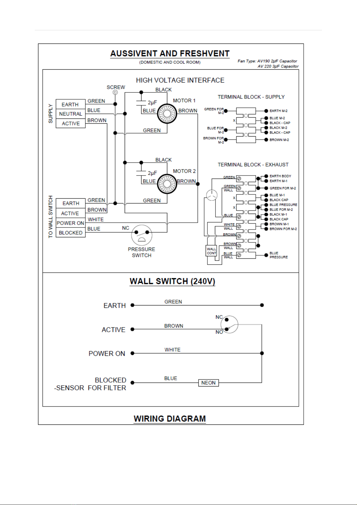
Wiring
The colour coded wires for the motors with their interconnections are shown below in the
wiring diagrams of illustrations 8 and 9.
4. COMMISSIONING
1. Ensure system is switched off at power board and unplugged.
2. The HRV is attached securely to the bracket, and the bracket is fastened to the hard
floor, roof, or wall or on a hard stand.
3. Make sure the filter is connected and all ducts are well harnessed on the collars with
duct tape.
P a g e | 12
Version10- March 2017 Eco Pacific Pty Ltd
Illustration 8: Wiring diagram for AussiVent and FreshVent models with AV fans

P a g e | 13
Version10- March 2017 Eco Pacific Pty Ltd
4. The outdoor air intake and indoor air intake should be well protected from children, and
from intrusion of birds, rodents, or insects.
5. Make sure that for cold room or add on with refrigerated units, the FreshVent HRV's drain
discharge is connected to the nearest ground water drain with appropriate gravity fall as
per these installation instructions.
6. Check load Amp runs are within design specs.
7. Ensure the air flow is in the right direction, is smooth and balanced if using a damper or
diffuser.
8. Ensure the ducts are not interfering any other ducts and are air tight.
9. Check the wall controller is mounted firmly on the wall with clear passage to the power
cord, and tele connector without interfering with its surrounding.
Make sure the wall controller’s vicinity is free for air flow from all sides to allow
natural air flow through its surrounding to sense air particles for CO2, and for any
movement/ motion of anybody around it.
10.On installation;
The installer has to fill in the following information for each installation and give
this manual to the customer;
Installation Details for warranty purpose
•Order number
•Customer Name
•Address of installation
•Delivery date
•Model name
•Model Number
•Serial number
•Installer’s full name
•Installer’s mobile number
•Dealer / Contractor company name address and telephone number
•Installation date
•Installer’s and Customers signatures

P a g e | 14
Version10- March 2017 Eco Pacific Pty Ltd
Illustration 9 wiring diagram for EcoVent with AV fans

P a g e | 15
Version10- March 2017 Eco Pacific Pty Ltd
5 AFTER INSTALLATION AND COMMISSIONING CHECKS
•Provide the customer with this booklet with installer’s signature on the warranty card
and customer’s details.
•Advise the customer of HRV operation and service and filter maintenance
requirements. The filter needs to be cleaned frequently depending upon the location.
•Ensure the installation site has been left clean and tidy with good workman ship.
•
6. TROUBLE SHOOTING
The HRV's are fitted with a pressure sensor inside the cabinet that is sensitive to filter
blockade. Filter blockade will compromise the air flow coming from the HRV. The motors
operate with the capacitors fitted inside the cabinet. If a problem persists, the following
table may help resolve the fault. If the problem cannot be fixed, call a qualified electrician or
factory / dealer authorised service technician.
Switch off the unit first, before the following checks are carried out.
Trouble
Possible solution
1. Fan are not blowing air
•Check the filter
•Check HRV receiving power
•Check power cables are intact
•Check the fans rotate freely
2. Air flow is very poor
•Check the ducting is not squeezed and
indoor air inlet is free to allow air flow.
•Check outdoor air inlet in the filter.
•Clean the filter
•Check fan motor operation
3. HRV is running noisy
•Check the fan wheel is not touching the
cabinet, if yes, call the serviceman
4. HRV is not operating
•Check the wall controller is switched on,
power in on, LEDs are on
5. Wall Controller is not working
•Check it is set to on, or auto, or off
7. WARRANTY
•The Eco Pacific ventilator units are covered with a Parts Only Warranty for 12 months
from the date of delivery to the customer.
•The Parts Only Warranty covers defective components that include fan motors, and
defective HRV and Filter Box.
•The Warranty does not cover damage to unit after delivery, misuse, abuse, normal
wear and tear, dirty filter, blown fuses, tripped circuit breakers, damage due to lightning,
voltage surge, or incorrect voltage supply. The warranty will not cover faults caused by
a faulty installation or maintenance done not in accordance with these instructions.
•Eco Pacific reserves the right to void the warranty where agreed payment terms have
not been met.
Special Note in regards to warranty
No alteration in the wring or in the cabinet is allowed. Any change to these ventilators
including changes to the connections of their wiring needs to be approved by Eco Pacific
Pty. Ltd. in writing. If this condition is not met, the manufacturer will not be able to honour its
expressed warranty.

P a g e | 16
Version10- March 2017 Eco Pacific Pty Ltd
8. SERVICE
8.1 FILTER
Pre-Filter: The standard filter box is fitted with a G4 polyester filter cassette as a standard,
which can be removed by manually opening the front grill cover. The filter can be removed
and gently washed with clean water. Alternatively, the filter can be gently vacuumed. The
filter should be replaced in the filter box with either face up.
Duct Collars: In case of service, no need to remove the duct collar fitted with the filter box.
If the duct connecting from filter to main ventilator needs to be relocated, the filter collar can
be relocated to other sides of the filter box.
Illustration 11: Filter Box and washable filter cassette
8.2 MOTOR
The ventilator is fitted with two motors - one each end of HRV. These motors work
independent of each other. The wiring connected to the motor fitted to the filter side is
shown below in illustration 12.
Note: First switch off the ventilator power from the power outlet.
To access a motor, remove the two base screws and the two lid screws of that motor end of
casing. Lift the side panels slightly above the base and pull out this end panel gently. See
the following view of the EcoVent with transformer and relays to separate 240 V from left
side to 24 V in the right-hand side terminal block. The AussiVent and FreshVent models
have a simple 240 V standard circuit.
To remove the motor, undo the two side bolts on each side of the casing and disconnect the
wires from the 240V terminal block. Please refer illustration 13 to see the base with 2
screws at each end. Now the motor can be removed from the back plate by undoing four
bolts- 2 each side accessed from outside. This will allow the new motor fastening on to the
back plate and repositioned in the cabinet as was previously. Connect the motor wiring to
the 240 V terminal block according to the wiring diagram shown above in the wiring diagram
section. Connect and switch on the power and check that the motor runs. If successful,
place the side panel on the base and fasten the two base screws, and replace the lid and
fasten the two top screws.

P a g e | 17
Version10- March 2017 Eco Pacific Pty Ltd
Illustration 12: Filter side power and wall controller connections for motor, and the H/X
Illustration 13: Base screws- 2 at each end to separate the side panels to service the motors

P a g e | 18
Version10- March 2017 Eco Pacific Pty Ltd
WARRANTY
ECO PACIFIC Heat Recovery Ventilator units are covered under Parts Only Warranty by Eco
Pacific Pty Ltd for a period of Twelve (12) Months from the date of sale.
The Parts Only Warranty covers defective components that include fan motors, and defective
manufacturing workmanship. The ECO PACIFIC heat exchanger is covered by a five-year
warranty.
The Warranty does not cover misuse, abuse, normal wear and tear, dirty filters, blown fuses,
tripped circuit breakers, damage due to lightning, voltage surge or incorrect voltage supply. The
Warranty may not cover faults caused by a faulty installation or maintenance not in accordance
with the recommended ECO PACIFIC maintenance schedule.
Eco Pacific Pty Ltd reserves the right to void the Warranty where the agreed payment terms have
not been met.
Any alterations to the ECO PACIFIC unit including changes or connections to the wiring need to
be approved by Eco Pacific Pty Ltd.
Order number:
Customer name:
Address of installation:
Delivery date:
Model name:
Model number:
Serial number:
Installer’s full name:
Installer’s mobile number:
Dealer / Contractor company name:
Address:
Telephone:
Installation date:
Manufacturer: Eco Pacific Pty Ltd, web: www.ecopacific.com.au
Email sales@ecopacific.com.au | Tel +61 3 9706 6228
Installer signature Signed: __________________
Name: __________________
Customer signature Signed: __________________
Name: __________________
This manual suits for next models
2
Table of contents
Popular Fan manuals by other brands


Lasko
Lasko M16900 Important instructions & operating manual

iLiving
iLiving ILG8WD24-2P owner's manual

Soltronic
Soltronic LTG-CF7007 Installation instruction

Tornado
Tornado Windshear 98782 Operation & maintenance manual

Anslut
Anslut 004840 operating instructions

Kendal Lighting
Kendal Lighting AC-24060 installation instructions

Rowan Elettronica
Rowan Elettronica 5314 instruction manual

Carrier
Carrier Idrofan 42GR ATM installation instructions

Sonnet
Sonnet FV-05VF2 installation instructions

Ebmpapst
Ebmpapst S6E710-AR03-01 operating instructions

Ebmpapst
Ebmpapst W2S130-AB03-34 operating instructions

Ebmpapst
Ebmpapst W4S250-DI02-01 operating instructions