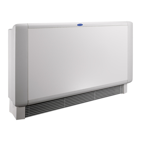
Carrier Idrofan 42GR ATM User manual
Other Carrier Fan manuals
Carrier
Carrier VL3A Guide
Carrier
Carrier CRECOMZR067A01 User manual
Carrier
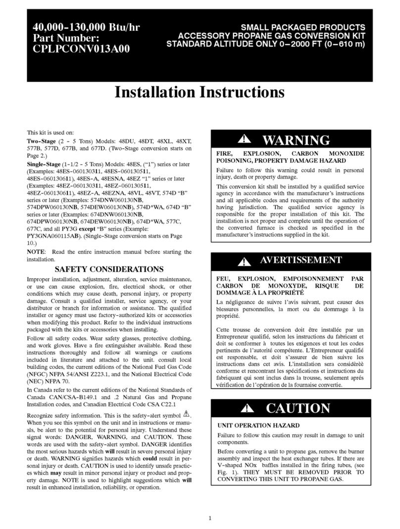
Carrier CPLPCONV013A00 User manual
Carrier
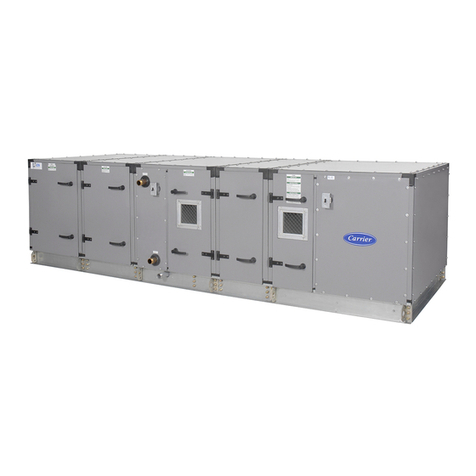
Carrier Aero 39MN Series Dimensions and installation guide
Carrier
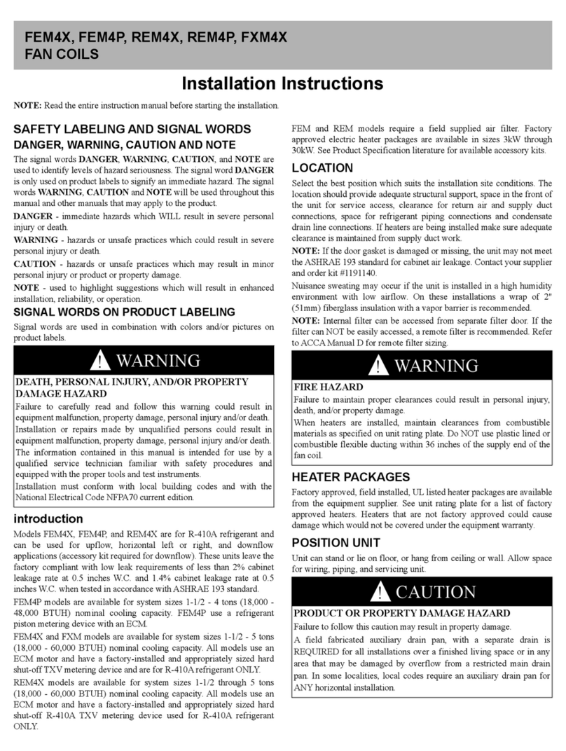
Carrier FEM4X User manual

Carrier
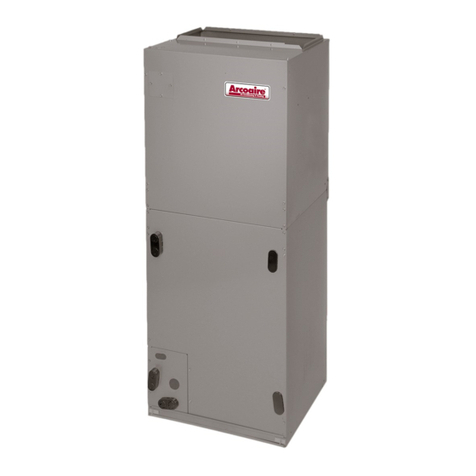
Carrier 40VM Series User manual

Carrier
Carrier 62X 03-35 User manual
Carrier
Carrier FXM4X User manual
Carrier
Carrier FB4CNP User manual
Carrier
Carrier AIRSTREAM 42BHC Operation manual
Carrier
Carrier CRECOMZR067A00 User manual
Carrier
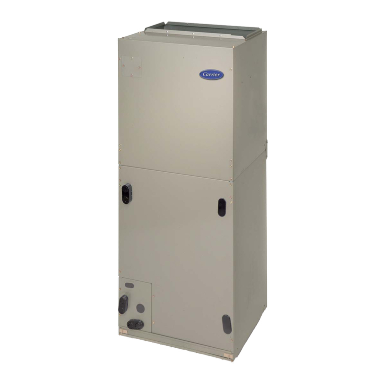
Carrier DLFSDA Series User manual
Carrier
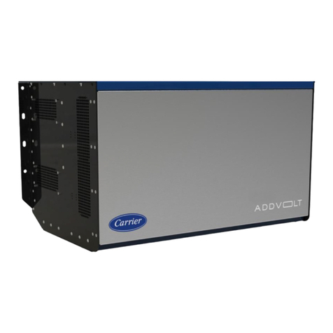
Carrier fb4c User manual
Carrier
Carrier AddVolt User manual

Carrier
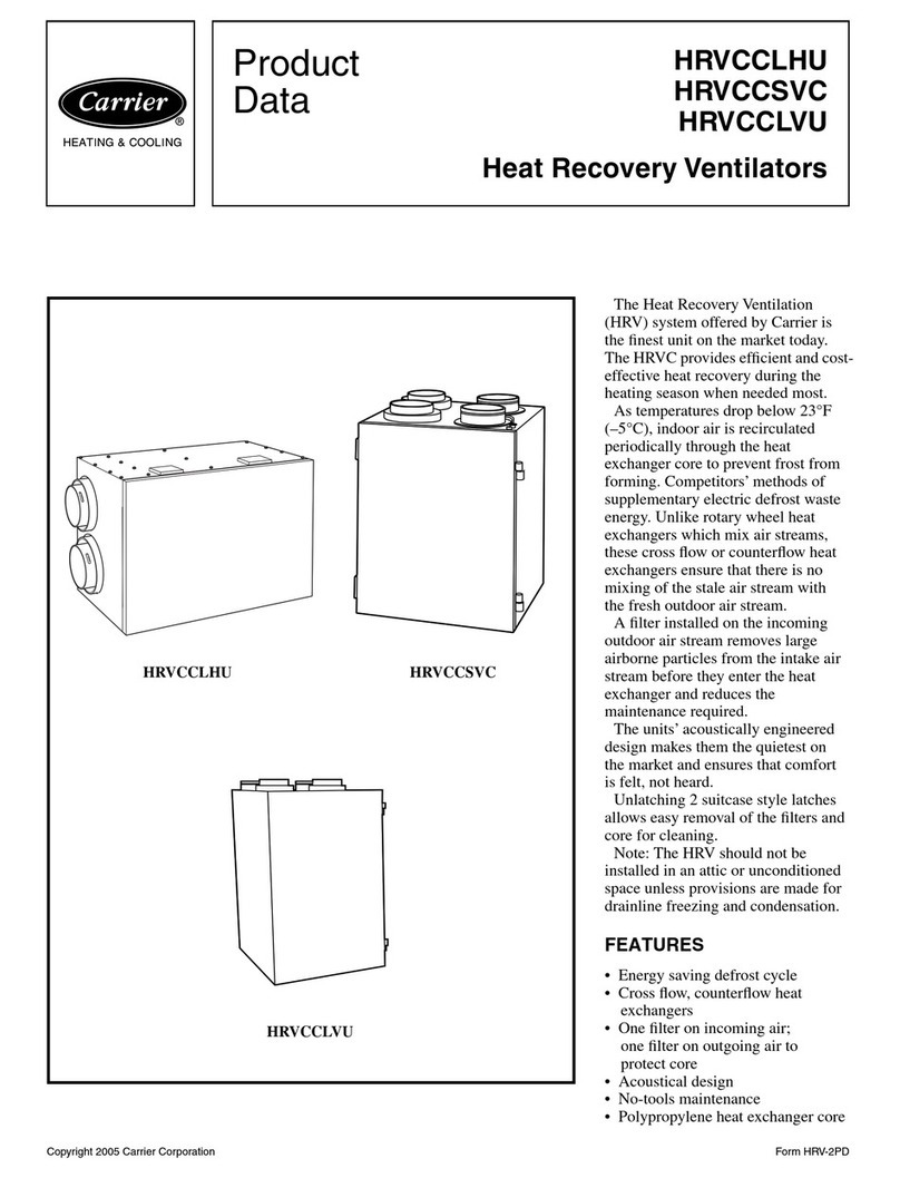
Carrier FSFXXAOA1180 Guide
Carrier
Carrier HRVCCLHU Operation manual

Carrier
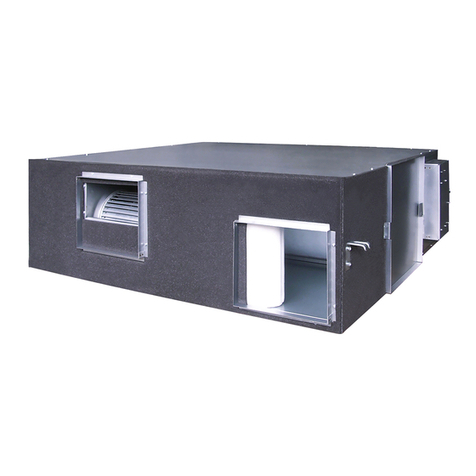
Carrier HRVCCLHU Instructions and recipes
Carrier
Carrier XCT7 40VH A-7G Series Installation instructions
Carrier
Carrier 38MPRA Series User manual
Carrier
Carrier HRVCCLHA User manual
Popular Fan manuals by other brands

ELTA FANS
ELTA FANS H03VV-F installation guide

Hunter
Hunter 20714 Owner's guide and installation manual

Emerson
Emerson CARRERA VERANDA CF542ORB00 owner's manual

Hunter
Hunter Caraway Owner's guide and installation manual

Panasonic
Panasonic FV-15NLFS1 Service manual

Kompernass
Kompernass KH 1150 operating instructions
