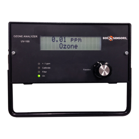
ECO Sensors UV-100 User manual

Eco Sensors Ozone Analyzer, Model UV-100 1
Division of KWJ Engineering Inc. User Manual, Rev. 2.0
sales@ecosensors.com or (800) 472-6626
USER MANUAL
OZONE ANALYZER
Model UV-100
Overview
The model UV-100 is a UV absorption analyzer designed specifically for ozone. It uses a mercury lamp
filtered for absorption at 254 nm. The Eco Sensors design is compact and uses the latest digital
microprocessor technology. The standard calibrated range of the UV-100 is 0-999 PPM. Its outputs are
an LCD digital display, 0-2.5 VDC, 4-20 mA, and a time and date stamped digital data stream for
external readout and data logging. The data output are via serial port and USB. There is also an
internal data logger which can store and forward approximately 90 hours of data. The theory of
operation is described in Appendix D.
Panel LEDs indicate: power, low Lamp output, low pump flow rate, and ozone concentration at the
sampling point exceeds 0.1 PPM.
The instrument is conditionally warranted for one year. Read the warranty statement at the end of this
manual.
Operation
Plug the AC adapter into AC power and plug the adapter's output plug into the power jack on the
instrument. Find the power switch on the rear panel and turn the instrument on. The green LED
"Power" indicator and the LCD display backlighting should illuminate. Allow at least 30 minutes
warm-up. More than 1 hour is preferred if time permits. Initial PPM readings may start out high and
possibly drop to zero for a few minutes. Then the readings will tend towards the actual value as the
systems settles into equilibrium.
The compact, high-speed sample pump in the instrument makes a buzzing sound. This is
normal.
Connect your sample feed tubing to the instrument's 1/4" input compression fitting. The inlet tubing
should be made of PTFE (Teflon), PFA, FEP, PVDF or some other inert material that does not destroy
ozone and that does not desorb plasticizers and other organics that can contaminate the flow path. The
length of tubing should be kept as short as possible (preferably not more than a few feet) to minimize
ozone destruction within the inlet tubing. Tygon, polypropylene (which may look like Teflon) and metal
tubing should not be used. FEP-lined Tygon tubing, which is used inside the instrument provides the
flexibility of Tygon with the inertness of FEP. A Teflon or PVDF inlet filter is highly recommended to
prevent internal contamination of the tubing and absorption cell by particulate matter. Filters and filter
holders are available through Eco Sensors.

Eco Sensors Ozone Analyzer, Model UV-100 2
Division of KWJ Engineering Inc. User Manual, Rev. 2.0
sales@ecosensors.com or (800) 472-6626
Front Panel
Back Panel
Power Input
12-24 VDC
@ 400mA
USB
Serial
Output
RS-232 Serial
2.5 VDC Output
4-20 mA Output
Control Relays
N/C COM N/O
Power Switch
Gas Sample Fitting
¼” nylon Swagelok

Eco Sensors Ozone Analyzer, Model UV-100 3
Division of KWJ Engineering Inc. User Manual, Rev. 2.0
sales@ecosensors.com or (800) 472-6626
Front Panel
LCD Display
The data displayed on the LCD depends on a variety of settings that are available via the Instrument
Menu and Function Knob.
By default, when the instrument starts, the front panel LCD will display the software version number
and the date & time, followed by ozone measurements, temperature & pressure measurements and the
date & time. Also available are average & instantaneous ozone measurements, log sample number and
flow rate.
LED Indicators
> 0.1 PPM:Measurement is above the OSHA Limit for 8-hour exposure to ozone
Low Flow:Input sample draw is less than the average of 1 LPM. Check the inlet tubing and filter for
obstruction.
Low Lamp:UV Lamp output is below normal levels. This can be caused by internal contamination or a
fault in the lamp or lamp circuitry. Contact our Technical Support if this light turns on.
Power:UV-100 is powered and operating.
Function Knob
The Function Knob is used to navigate the instrument menu. The knob rotates clockwise or
counterclockwise to move the selection cursor around the menu. The knob depresses like a pushbutton
to enter the menu and activate a cursor selection.

Eco Sensors Ozone Analyzer, Model UV-100 4
Division of KWJ Engineering Inc. User Manual, Rev. 2.0
sales@ecosensors.com or (800) 472-6626
Instrument Menu
To access the instrument menu, push and hold the Function Knob on the front panel until:
Menu
is displayed, then release the knob. After a few seconds, the menu selections will appear:
Menu
Dat Avg Cfg Lmp
Dat (Data Logging), Avg (Averaging), Cfg (Configuration), and Lmp (Lamp) are submenus that may be
selected. The blinking cursor at the bottom of the display indicates which submenu item is selected.
Rotating the Function Knob in either direction will move the cursor between items. Pushing the
Function Knob will enter the submenu of the selected item. To exit the menu or submenu, select the
back arrow () and press the knob.
Averaging (Avg) Submenu:
From the instrument menu, select Avg and push the Function Knob. The averaging submenu will
appear:
Avg Menu
10s 1m 5m 1h
The options are represented in terms of averaging times. The minimum measurement cycle of the
UV-100 is 10 s, therefore the default selection of 10 s represents no additional averaging. A 1 m
average time will average 6 discrete measurements. A 5 m averaging time will average 30 discrete
measurments. A 1 h averaging time will average 360 discrete measurements. While in averaging mode,
the front panel display will alternate between the instantaneous 10 s measurement and the averaged
value at 5 s intervals.
Data (Dat) Logging Submenu:
From the instrument menu, select Dat and push the Function Knob. The data submenu will appear:
Dat Menu
Xmt Log End

Eco Sensors Ozone Analyzer, Model UV-100 5
Division of KWJ Engineering Inc. User Manual, Rev. 2.0
sales@ecosensors.com or (800) 472-6626
Start Log:
To start logging to the internal memory, select Log. You will be prompted to overwrite any data that is
stored in the instrument:
Overwrite Data?
No Yes
If there is data stored in the instrument that you need to keep, select No and follow the instructions
below to download the data to a computer. Otherwise, to erase all previous data and start a new log,
select Yes. This will start the log and return to the Dat menu. The UV-100 will now store all readings
until the internal memory is filled.
Power Loss:
The log data is retained when the UV-100 loses power or when it is turned off with the power switch. In
these circumstances, when power is returned to the UV-100, the note: “Data Interruption” is written to
the log file and then logging is resumed. This allows the UV-100 to be used remotely in one or multiple
locations and then returned to a computer for download.
Logging with Averaging Enabled:
The UV-100 can store up to 32,736 lines of data. When averaging is enabled, data is logged at the
same rate as the averaging. The approximate log duration is indicated below for each setting.
Averaging
Approximate
Log Duration
10 s
3.8 days
1 m
22.7 days
5 m
113 days
1 h
3.7 years
Stop Log:
To stop logging to the internal memory, select End from the Dat menu.
Transmit Log:
To transmit the contents of the log to a computer, setup the USB connection as described in the
section: “Digital Data Output” and then select Xmt from the Dat menu.
If you select Xmt prior to stopping the log with End, then the UV-100 will automatically execute the End
command prior to transmitting the log.

Eco Sensors Ozone Analyzer, Model UV-100 6
Division of KWJ Engineering Inc. User Manual, Rev. 2.0
sales@ecosensors.com or (800) 472-6626
Configuration (Cfg) Submenu:
From the instrument menu, select Cfg and push the Function Knob. The configuration submenu will
appear:
Cfg Menu
D/T Cal I/O Unt
Date and Time (D/T):
From the Cfg submenu, select D/T and push the Function Knob. The D/T submenu will appear:
D/T: 14:32:21
17/10/2016
The time format is 24-hour, military time (HH:MM:SS). The date format is European standard
(DD/MM/YYYY). To change a value, rotate the knob to move the cursor to the value you want to
change, push the knob to activate the value, rotate the knob to change the value, and then push the
knob again to store the value. You may then rotate the knob to select a different value and repeat the
process.
Calibration (Cal):
The instrument is calibrated at the factory where slope and offset parameters are entered into the
instrument’s memory. These preset calibration parameters are given in the instrument’s Birth Certificate
and recorded on the calibration sticker on the back of the instrument. However, the calibration
parameters may be changed by the user.
The instrument zero may drift by a few ppb over time. For this reason, frequent zeroing of the
instrument using an external ozone scrubber, to determine the offset, may be desirable. Any change in
the slope (gain) of the instrument is likely due to a serious problem such as contamination, an air leak,
obstruction of air flow, or loss of catalytic activity by the internal ozone scrubber. The slope can be
adjusted by the user but in most cases, it is recommended that the instrument is returned for service
and recalibration.
From the Cfg submenu, select Cal and push the Function Knob. The Cal submenu will appear:
Cal Menu
Fm O3

Eco Sensors Ozone Analyzer, Model UV-100 7
Division of KWJ Engineering Inc. User Manual, Rev. 2.0
sales@ecosensors.com or (800) 472-6626
To change the calibration factor for the flow meter, select Fm from the Cal Menu and push the
Function Knob. The submenu will appear:
Fm Cal Menu
Fm= 0.92
This is a multiplicative factor that will increase the flow rate if you increase the value. Adjust this value
to correct the flow value when comparing it to a calibrated volumetric flow meter connected to the inlet
of the instrument.
To change the calibration factors for the ozone measurement, select O3 from the Cal Menu and push
the Function Knob. The submenu will appear:
Cal Menu
Z= -3 S= 1.01
Zis the offset applied (in this case -3 ppb) and Sis the slope applied (in this case 1.01). The value of Z
is added to the measured ozone value, and the value of Sis then multiplied by the measured ozone
value. During calibration, Zis set to 0 and Sis set to 1.00. If the instrument reads an average of 3 ppb
with the external scrubber in place, the value of Zshould be set to -3. If after correction for the zero, the
instrument consistently reads 2% low (in the presence of a precisely known ozone concentration), the
value of Sshould be set to 1.02.
To change a value, rotate the knob to move the cursor to the value you want to change, push the knob
to activate the value, rotate the knob to change the value, and then push the knob again to store the
value. You may then rotate the knob to select a different value and repeat the process.
Inputs & Outputs (I/O):
From the Cfg submenu, select I/O and push the Function Knob. The I/O submenu will appear:
I/O Menu
Bdr Ext Hrs
Baud (Bdr):
The baud rate is not adjustable at this time.

Eco Sensors Ozone Analyzer, Model UV-100 8
Division of KWJ Engineering Inc. User Manual, Rev. 2.0
sales@ecosensors.com or (800) 472-6626
External Outputs (Ext):
The UV-100 includes analog voltage & current outputs as well as a relay that may be used to interface
with other devices. Select Ext from the I/O submenu and push the Function Knob. The submenu will
appear:
Ext Menu
REL1 REL2 V_OUT
Relays (REL1 & REL2):
To set the ON/OFF limits of the relays, select REL1 or REL2 from the I/O submenu and push the
Function Knob. The settings will appear:
On= 0009.90 ppmv
Off= 0010.10
To change a value, rotate the knob to move the cursor to the value you want to change, push the knob
to activate the value, rotate the knob to change the value, and then push the knob again to store the
value. You may then rotate the knob to select a different value and repeat the process.
With the settings in the example, the relay will close (pass current) until the ozone concentration
exceeds 10.10 ppm. Above this concentration the switch relay will open. The relay will not close again
until the ozone concentration drops below 9.90 ppm. In this way, for example, ozone concentration from
an ozone generation could be controlled in the range 9.90 to 10.10 ppm.
Physical connections to the relays are made via the supplied screw connectors. When viewing the
connectors from the rear of the instrument, REL1 is on the bottom and REL2 is on the top. The right
terminal is normally open (N/O), the center terminal is common (COM), and the left terminal is normally
closed (N/C).
Analog Voltage and Current Outputs (V_OUT):
To change the scaling of the analog voltage and current outputs, select V_OUT from the I/O submenu
and push the Function Knob. The settings will appear:
2.5V=0001.00 ppm
20mA=0001.00 ppm
To change a value, rotate the knob to move the cursor to the value you want to change, push the knob
to activate the value, rotate the knob to change the value, and then push the knob again to store the
value. You may then rotate the knob to select a different value and repeat the process.

Eco Sensors Ozone Analyzer, Model UV-100 9
Division of KWJ Engineering Inc. User Manual, Rev. 2.0
sales@ecosensors.com or (800) 472-6626
While any scaling factor may be defined, the analog voltage and current scaling factors are tied
together and cannot be adjusted independently.
With the settings in this example, the output scaling factor is set as 2.5 V (full scale) = 1.00 ppm; that is,
1 V = 0.40 ppm. Also, the current output will be scaled such that the full scale of 20 mA corresponds to
1.00 ppm. A reading of zero ozone concentration will be output as 0 V and as 4 mA.
The analog output are available as part of the DB9 connector on the back of the UV-100. When viewing
the connector from the rear of the instrument, the pin numbers are:
The analog voltage signal is measured across pins 1 (+) and 5 (GND). The analog current signal is
measured across pins 9 (+) and 5 (GND).
Hours of Operation (Hrs):
The UV-100 logs the total number of hours that it has been in use. This is helpful for determining when
the instrument should be serviced. Select Hrs and push the Function Knob. The total number of hours
will be displayed.
Units (Unt):
From the Cfg submenu, select Unt and push the Function Knob. The Unt submenu will appear:
Unt Menu
T/P O3
Changing units for ozone is not available at this time. To change the units for temperature and
pressure, select T/P and push the Function Knob. The submenu will appear:
T/P Units Menu
T:KP:torr
For temperature, the units of °C or K may be selected. For pressure, the units of mbar or torr may be
selected. To change a value, rotate the knob to move the cursor to the value you want to change, push
the knob to activate the value, rotate the knob to change the value, and then push the knob again to
store the value. You may then rotate the knob to select a different value and repeat the process.
1 2 3 4 5
● ● ● ● ●
● ● ● ●
6 7 8 9

Eco Sensors Ozone Analyzer, Model UV-100 10
Division of KWJ Engineering Inc. User Manual, Rev. 2.0
sales@ecosensors.com or (800) 472-6626
Lamp (Lmp) Submenu:
If the instrument measurements are excessively noisy (with a standard deviation above 2 ppb) or are
always near zero in the presence of ozone, it is useful to perform a UV lamp check. Before performing
the test, allow the instrument to warm up for 30 minutes.
From the instrument menu, select Lmp and push the Function Knob. The display will momentarily
read:
Lamp Test
The diagnostic results will then be displayed after a short delay, for example:
PDV= 0.89801 V
1.2 +/- 4.85
The PDV value should be in the range: 0.6 to 2.2 V and the +/- value should be less than 2.5. If either
of these values are out of range, please contact our Technical Support.
Digital Data Output
The UV-100 may be connected to a computer (via USB or serial cable) to transmit real-time data or
internally logged data. 3rd-party terminal programs such as TeraTerm or puTTY are available online for
interfacing with the UV-100. These programs should be setup for serial communication with the UV-100
on the correct COM port with the following settings:
Baud rate: 9600
Data Bits: 8
Parity: None
Stop Bits: 1
When the UV-100 is connected to a computer with these settings, the instrument will output a line of
data at the rate defined by the averaging setting (Menu > Avg).
When the instrument is not in logging mode, the data output will be in the following form:
0.00,304.7,739.6,731,1.057,07/03/16,15:14:39
0.00,304.7,739.6,745,1.059,07/03/16,15:14:49
0.00,304.7,739.6,742,1.060,07/03/16,15:14:59
0.00,304.7,739.6,746,1.060,07/03/16,15:15:09
0.01,304.7,739.6,748,1.061,07/03/16,15:15:19
0.01,304.7,739.5,761,1.061,07/03/16,15:15:29
0.01,304.7,739.5,764,1.061,07/03/16,15:15:39
where the columns of data are:
PPM, Cell Temperature (K), Cell Pressure (torr), Flow Rate, Photodiode Voltage, Date, Time

Eco Sensors Ozone Analyzer, Model UV-100 11
Division of KWJ Engineering Inc. User Manual, Rev. 2.0
sales@ecosensors.com or (800) 472-6626
When the instrument is logging, the data output will be in the following form:
1,0.00,304.7,739.6,750,1.060,07/03/16,15:16:59
2,0.00,304.7,739.6,738,1.059,07/03/16,15:17:09
3,0.00,304.7,739.6,743,1.059,07/03/16,15:17:19
4,0.00,304.6,739.6,736,1.058,07/03/16,15:17:29
5,0.00,304.6,739.6,743,1.058,07/03/16,15:17:39
6,0.00,304.6,739.5,737,1.057,07/03/16,15:17:49
7,0.01,304.6,739.5,739,1.057,07/03/16,15:17:59
8,0.01,304.6,739.6,727,1.056,07/03/16,15:18:09
Logging Ended
where the columns of data are:
Sample Number, PPM, Cell Temperature (K), Cell Pressure (torr), Flow Rate, Photodiode Voltage, Date, Time
To download internally logged data, navigate to Menu > Dat > Xmt. This will print all the stored data
lines to the terminal program.
Logged Data
1,0.00,304.6,739.5,749,1.059,07/03/16,15:16:59
2,0.00,304.6,739.5,737,1.059,07/03/16,15:17:09
3,0.00,304.6,739.5,743,1.058,07/03/16,15:17:19
4,0.00,304.6,739.5,735,1.058,07/03/16,15:17:29
5,0.00,304.6,739.5,742,1.057,07/03/16,15:17:39
6,0.00,304.6,739.5,737,1.057,07/03/16,15:17:49
7,0.01,304.6,739.5,738,1.056,07/03/16,15:17:59
8,0.01,304.6,739.5,727,1.056,07/03/16,15:18:09
End of Log
where the columns of data are:
Sample Number, PPM, Cell Temperature (K), Cell Pressure (torr), Flow Rate, Photodiode Voltage, Date, Time
Different programs have different methods for saving or logging this data to a file. Please refer to the
user manual of the terminal program you are using for more details.
Accessing the Serial Menu
When the UV-100 is connected to a computer (via USB or serial cable), as described above,
commands can be sent to adjust instrument parameters and initiate logging tasks. Listed below are the
lower case command letters for performing operations while the instrument continues to measure.
l Start logging and delete previously logged data
t Transmit logged data
e End logging
h Output serial data line header
m Serial menu

Eco Sensors Ozone Analyzer, Model UV-100 12
Division of KWJ Engineering Inc. User Manual, Rev. 2.0
sales@ecosensors.com or (800) 472-6626
If the letter m is sent as a command, menu> will be displayed in the terminal emulator window. When
the serial menu is accessed, the instrument is no longer making measurements; it is waiting for the next
command to be entered. The following is the list of menu items accessible from this point:
x Exit menu and return to measuring
l Start logging and delete previously logged data
t Transmit logged data
e End logging
h Output serial data line header
a Displays list of possible averaging times and the number that must be entered to change to the
desired averaging time
z Displays current zero calibration setting and waits for new setting followed by a carriage return
s Displays current slope calibration setting and waits for new setting followed by a carriage return
c Clock menu, displays current date and time and waits for d or t to be entered
From clock menu,
d Asks to enter date in DDMMYY format
t Asks to enter time in HHMMSS format
REL2 can operate as an ON/OFF limit switch, as described in the Configuration section, above.
Alternatively, REL2 can be set to operate when certain diagnostic tests have failed (cell temperature,
cell pressure, flow rate, photodiode voltage). The following are related commands that can be set from
the serial menu:
oChange relay 2 operation for temperature, pressure, flow, and photodiode voltage
qChange relay 2 operation for ozone
1Enable temperature inclusion for relay 2
!Disable temperature inclusion for relay 2
2Enable pressure inclusion for relay 2
@Disable pressure inclusion for relay 2
3Enable flow inclusion for relay 2
#Disable flow inclusion for relay 2
4Enable pdv inclusion for relay 2
$Disable pdv inclusion for relay 2
? Indicates the enable/disable status of the diagnostic tests
The limits for each of the diagnostic tests are listed below:
Temperature LOW: 5 HIGH: 50
Pressure LOW: 500 HIGH: 1100
Flow LOW: 400 HIGH: 2000
Photodiode Voltage LOW: 0.6 HIGH: 2.45

Eco Sensors Ozone Analyzer, Model UV-100 13
Division of KWJ Engineering Inc. User Manual, Rev. 2.0
sales@ecosensors.com or (800) 472-6626
Calibration
The Eco Sensors, Inc., UV-100 is calibrated to a reference instrument whose calibration is traceable to
the US government standards agency, NIST. The UV-100 has internal sensors and programming to
correct its calibration for temperature and pressure. Calibration data and date for your UV-100 are
included in the document package included with the instrument.
Recalibration can be done simply and quickly at Eco Sensors, Inc.
Service and Maintenance
The Ozone Monitor is designed to be nearly maintenance-free. There are no user serviceable parts
inside the UV-100. Opening the enclosure will void the warranty.
Input Filter: The input sample tubing filter is recommended for any operational environment. A length
of Tygon TE-200 Teflon coated tubing and a disposable micromesh disk filter is provided. It is
recommended that the input filter is replaced at 6 month intervals or more frequently in dusty or harsh
environments.
In severe condensing humidity environments a small moisture trap may be needed on the input to
protect the UV-100’s internal tubing from condensing moisture internally. Contact Technical support for
more information.
Components with a limited lifetime are the air pump (~5,000 hours), lamp (~20,000 hours) and solenoid
valve (rarely fails). It is recommended that the instrument be returned to Eco Sensors if any of these
components fail.
The following are indications of various instrument malfunctions.
Air Pump Failure: The instrument will not make a humming sound. Also, the circuit breaker may
prevent the instrument from powering up if the motor in the air pump develops a short.
Lamp Failure: The ozone measurements will be erratic and the Lamp Test will show 0.0 volts for the
photodiode voltage.
Solenoid Valve Failure: The ozone readings will be low and average to close to zero if the solenoid
valve is not switching. Partial switching of the solenoid valve will cause the instrument to read low but
not zero.
Contaminated Flow Path: The instrument will typically have a large positive or negative offset and the
ozone readings will be low once corrected for the measured offset.

Eco Sensors Ozone Analyzer, Model UV-100 14
Division of KWJ Engineering Inc. User Manual, Rev. 2.0
sales@ecosensors.com or (800) 472-6626
AC Adapter
The Eco Sensors P-20-15 adapter is included with every UV-100. This adapter is suitable for Type A
power outlets (North America). Adapters for other locations may be available for special order from Eco
Sensors. Otherwise, adapters should be purchased locally that fit local wall sockets and conform to
local codes. The output should be 12 VDC at 1250 mA. The DC plug is 5.5/2.1 mm x 10 mm, center
positive (+). For more details, see our Tech Note P-101.
Precautions
Allow at least 30 minutes warm-up.
Read all instructions in this manual.
Keep the instrument dry. Never let water or other liquids into the sensor.
Do not drop the instrument or subject it to continuous vibration.
Do not store in high levels of dust.
Do not clean the instrument with cleaning chemicals or solvents. Clean it with a damp cloth.
Do not operate near heavy aerosols (spray) usage or where oxygen is being administered.
Call a qualified electrician if you have any doubts about voltages, currents, electrical practice, etc.
While not necessary for typical uses, for highest precision results in electrically noisy locations, the
instrument should be grounded to earth to achieve maximum stability.
UV-100 Options
Pelican case PN: 20-0598
Hi Efficiency Sample Line Filter and Housing PN: FLTRS(LARGE)
Hi Efficiency Sample Line Filter Elements, 10pcs PN: FILTERPAK(LARG)
Heavy Duty External Pump(replaces internal pump) PN: EXT PUMP(HD)

Eco Sensors Ozone Analyzer, Model UV-100 15
Division of KWJ Engineering Inc. User Manual, Rev. 2.0
sales@ecosensors.com or (800) 472-6626
Specifications
Sensor Technology:
UV Absorption
Measurement Range:
0-999 ppm
Resolution:
0.01 ppm
Precision:
± 2% of reading or ± 0.01 ppm, whichever is greater
Accuracy:
± 2% of reading or ± 0.01 ppm, whichever is greater
Response Time:
< 60 s
Measurement Rate:
10 s
Temperature Compensation:
Yes
Recommended Temperature Range:
10-40 °C
Recommended Humidity Range:
0-80% RH
Power Requirements:
11-28 VDC, nominally 500 mA at 12 V, 6.0 watt
Enclosure Size:
3.75 x 8.5 x 8.5 in (9.5 x 21.6 x 21.6 cm)
Weight:
4.0 lb (1.8 kg)

Eco Sensors Ozone Analyzer, Model UV-100 16
Division of KWJ Engineering Inc. User Manual, Rev. 2.0
sales@ecosensors.com or (800) 472-6626
Warranty
This product is warranted against defects in materials and workmanship for one year following the date
of purchase by the original owner. This warranty does not include damage to the product that results
from misuse, accident, dropping, modifications or alterations, and it does not apply if the instructions in
this manual are not followed, or if the unit is otherwise used outside its intended specifications.
If a defect develops during the warranty period, Eco Sensors, in its sole discretion, will repair the
instrument or replace it with a new or reconditioned model of equivalent quality. In the event of
replacement with a new or reconditioned instrument, the replacement unit will continue the warranty of
the original unit.
If the product should become defective during the warranty period, please return it through your
distributor, or call Eco Sensors at (800) 472-6626 or e-mail at sales@ecosensors.com to receive return
instructions and a Return Materials Authorization (RMA) number.
Except as provided herein, Eco Sensors makes no warranties, expressed or implied, including
warranties of merchantability and fitness for a particular purpose. Eco Sensors shall not be liable for
loss of use of this instrument or other incidental or consequential damages, expenses or economic loss,
or claims for such damage or economic loss.
RECORD YOUR SERIAL NUMBER HERE
__________________________________
KEEP THIS MANUAL AND WARRANTY FOR YOUR RECORDS.
Eco Sensors is a registered trademark of Eco Sensors, Division of KWJ Engineering, Inc.
© Eco Sensors, Division of KWJ Engineering, Inc. 2015.
For brochures, application and tech notes, and other useful information, visit our extensive website at

Eco Sensors Ozone Analyzer, Model UV-100 17
Division of KWJ Engineering Inc. User Manual, Rev. 2.0
sales@ecosensors.com or (800) 472-6626
APPENDIX A
USB Driver Installation
Items Required
UV-100 Ozone Monitor
USB Cable
PC Computer
USB to UART Driver Disk
(or download drivers from the Firmware and Software Section on our support webpage:
www.ecosensors.com/support/)
Driver Installation
With the UV-100 off, attach USB cable from the instrument to a USB port on the computer.
Turn the UV-100 on. The computer will fail to locate drivers on its own.
On a Windows computer, locate the Device Manager.
Within the list on the device manager, locate the device that is not correctly installed
Right-click on the device and choose “Update Driver Software”
In the window that opens, choose “Browse my computer for driver software”
In the next window, click the “Browse” button and then navigate to the driver file (unzip this file first)
Select the unzipped file: cdc_NTXPVista7.zip and click “Ok”
Follow any other remaining on-screen instructions.
APPENDIX B
Using the USB Connection
Determining the COM Port
With the instrument connected, turned on, and the drivers installed, determine which COM port the
connection is using:
If using Windows, locate the “Device Manager”
Press the “+” sign next to “Ports”.
The COM port number is indicated in parenthesis, next to the “USB to UART” listing. This number
will be used for the settings for the terminal program.
Using the Connection
The UV-100 may be connected to a computer (via USB or serial cable) to transmit real-time data or
internally logged data. 3rd-party terminal programs such as TeraTerm or puTTY are available online for
interfacing with the UV-100. These programs should be setup for serial communication with the UV-100
on the correct COM port with the following settings:
Baud rate: 9600
Data Bits: 8
Parity: None
Stop Bits: 1

Eco Sensors Ozone Analyzer, Model UV-100 18
Division of KWJ Engineering Inc. User Manual, Rev. 2.0
sales@ecosensors.com or (800) 472-6626
APPENDIX C
Pinout of the DB-9 Connector
Rear view of the UV-100 DB-9 Connector (Male)
Pin Description:
1 0-2 V Analog Signal Out
2 TXD RS-232 Transmit
3 RXD RS-232 Receive
4 No Connection
5 Ground
6 No Connection
7 No Connection
8 No Connection
9 4-20 mA Analog Signal Out
1 2 3 4 5
● ● ● ● ●
● ● ● ●
6 7 8 9

Eco Sensors Ozone Analyzer, Model UV-100 19
Division of KWJ Engineering Inc. User Manual, Rev. 2.0
sales@ecosensors.com or (800) 472-6626
APPENDIX D
Application Examples
Two examples of common applications for the UV-100 are described below. These are shown for
reference only. For more details contact Eco Sensors Tech Support.
Remediation Example
Ozone’s cleaning and disinfecting properties are well known. Its ability to break down bacteria and a
wide range of contaminants with almost no residue is just beginning to be used in real-world
applications. The following is an example of one of Eco Sensor’s Customer setup to remove mold from
rooms and combined spaces in flooded homes:
Items:
UV-100
Ozone generator(s) (UV 550 Pro or similar)
Power relay (s) for generator and fan (optional)
Indicator light for OSHA limit
4-20 mA current loop
To destroy mold the space is held at a very high Ozone level for a predetermined amount of time. The
generator is controlled using the set point relay on the back of the UV-100 to hold Ozone.
After the Ozone “dwell” interval is complete, generator power is shut off or UV-100 generator ON level
is set to zero. Over the course of a few hours the Ozone will decay to zero. In this particular installation
an indicator light was tied to the 4-20 mA output to give an “all clear” indication when the space was
reading under the OSHA immediate limit of 0.3 PPM. 4-20 mA scale is set to 4 mA = 0 PPM, 20 mA = 1
PPM.
Remediation Space
UV-100
Ozone
Generator
4-20mA
Current
Loop
Safety
Indicator
Relay Output
4-20 mA Output

Eco Sensors Ozone Analyzer, Model UV-100 20
Division of KWJ Engineering Inc. User Manual, Rev. 2.0
sales@ecosensors.com or (800) 472-6626
Cold Condensing Example
Items:
UV-100
Tygon SE-200 Teflon lined tubing, length variable
Small moisture trap
Ozone generator (if Ozone control is required)
In some applications the environment under measurement is outside the temperature and/or humidity
range of the UV-100. Several methods can used to shield the UV-100 from theses extremes.
The UV-100 is kept isolated by being outside the cold space and by using a long length of inlet tubing,
the majority of which coiled outside the cold space. This allows for the inlet sample to be warmed to an
acceptable level before measurement.
Condensation from the temperature change is eliminated using a small moisture trap spliced into the
inlet line.
Due to the extra length of inlet tube and moisture trap, offsets will need to be made for measurements.
The reading will be delayed depending on the length of tube, as much as an extra minute or more.
Testing with high Ozone pulses can determine this delay.
The reading will also be attenuated as much as 5% due to the inlet length and loss from the moisture
trap.
Ozone
Generator
UV-100
Cold/Hot
Ozone Space
Moisture
Trap
Cooling/Warming
Coil
Other manuals for UV-100
1
Table of contents
Other ECO Sensors Measuring Instrument manuals
