ECO Sensors UV-100 User manual

ECO SENSORS, INC.
OZONE ANALYZER
Model UV-100
INSTRUCTIONS FOR USE
GENERAL
The model UV-100 is a UV absorption analyzer
designed speci ically or ozone. It uses a mercury
lamp iltered or absorption at 254 nm as is typical o
other commercial instruments. The Eco Sensors, Inc.,
design is very compact and uses the latest digital
microprocessor technology. The UV-100 covers three
ranges: 0-1, 0-10 and 0-999 PPM. Its outputs are a
LCD digital display, 0-2.5 VDC, 4-20 mA, and a time
and date stamped digital data stream or external
readout and data logging. The data output are via
serial port and USB. There is also an internal data
logger which can store and orward approximately 36
hours o data. The theory o operation is described in
Appendix D.
Panel LEDs indicate "on", low lamp output, low low rate, and the ozone concentration at
the sampling point exceeds 0.1 PPM.
The instrument is conditionally warranted or one year. Read the warranty statement at
the end o this manual.
OPERATION
Plug the AC adapter into AC power and plug the adapter's output plug into the power
jack on the instrument. Find the power switch on the rear panel and turn the instrument
on. The green LED "on" indicator and the LCD display backlighting should illuminate.
Allow at least 1/2 hour warm-up. More than 1 hour is pre erred i time permits. Initial
PPM readings may start out high and possibly drop to zero or a ew minutes. Then the
readings will tend towards the actual value as the systems settles into equilibrium.
The compact, high-speed sample pump in the instrument makes a buzzing sound.
This is normal.
1

Connect your sample eed tubing to the instrument's 1/4" input compression itting or via
a small optional sample line ilter. The Tygon eed tubing is Te lon lined polyethylene so
that the ozone is lowing through Te lon, but the tubing is more lexible than pure Te lon.
The range is selected automatically by the instrument unless it is set to a pre erred
range by the Function control on the ront panel. See urther instructions on Range
Selection below.
Front Panel
Back Panel
Use only the sample air ilter supplied with the instrument. Other ilters, especially those
with a greater pressure drop, can materially a ect the readings. This will be noticed i the
instrument's zero is signi icantly above 0 ppm with no ozone present.
2
12-24 V C @
400mA Input
USB Serial
Output
RS232 Serial
2.5 V C Output
4-20 mA Output
Ozone Control Relay
N/O COM N/C
DATA READOUT
Ozone readings are displayed continuously on the panel liquid crystal display (LCD).
The displayed data is updated every 10 seconds. Voltage, current loop, and digital
outputs on the rear panel are described in Outputs to External Equipment below.
FUNCTION CONTROL
The panel Function Control is to access the internal microprocessor. The knob is gently
but irmly pushed in, held there until a response is seen in the LCD display, released,
turned to select a unction, and then pressed momentarily to activate the selected
unction.
MENU SECTIONS
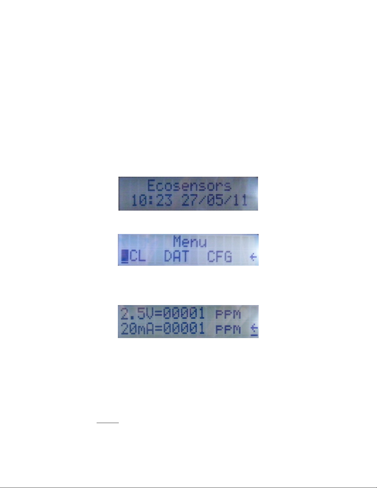
Upon start up, the UV-100 will display so tware version number then date and time.
Pressing the unction knob will open the main menu.
Scale (SCL) Menu:
Pressing the unction knob again enters the scale menu.
The UV-100 independently controls the 0-2.5 VDC and 4-20mA scales. This eature is
very use ul in multi-level control applications. See the Application Examples section or
more in ormation.
The scale can be set to ull scale = to 1 PPM to 999 PPM. Setting the scale maximum
near the normal operational Ozone levels will better resolution at lower readings.
Selecting the <- arrow returns to the previous menu.
NOTE: The SCL function affects ONLY the analog output (0-2.5V an 4-20mA).
This isplay always rea s 0.00-999 ppm.
3
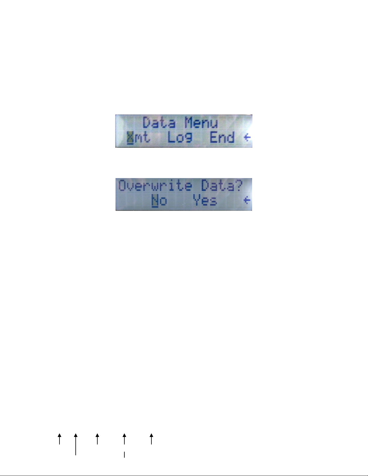
ata ( AT) Menu:
The Data menu controls the internal logging eature o the UV-100. The UV-100 can
store approximately 36 hours o readings. For long term data logging techniques see the
Application Examples section.
To begin logging, select LOG. You will be prompted to overwrite and data already
stored.
The UV-100 will now store all readings at 10 second intervals until internal memory is
illed. The data is retained even i the unit is powered down or unplugged so the UV-100
can be used remotely and returned to a computer or download.
END command stops storage o measurements. Data will be kept in memory until an
Overwrite command is given.
Output
To connect the UV-100 to the computer, re er to Connections To External Equipment
section.
To download, connect the UV-100 to a computer and select XMT. The UV-100 will
output all measurement records in memory in a comma delimited serial stream.
Output Examples:
Normal Mode:
0.00,298.4,575.8,09:34:38,27/05/2008
0.00,298.4,575.8,09:34:48,27/05/2008
0.04,298.4,575.7,09:34:58,27/05/2008
0.02,298.4,575.8,09:35:08,27/05/2008
0.03,298.4,575.8,09:35:18,27/05/2008
0.03,298.4,575.8,09:35:28,27/05/2008
0.03,298.4,575.8,09:35:38,27/05/2008
0.03,298.4,575.8,09:35:48,27/05/2008
0.03,298.4,575.8,09:35:58,27/05/2008
4

Ozone Temperature (Kelvin) Date (DD/MM/YYYY)
Pressure (Torr) Time (24H)
Logging Mode:
Logging Started
1,0.00,298.4,575.7,09:39:29,27/05/2008
2,0.00,298.4,575.8,09:39:39,27/05/2008
3,0.00,298.4,575.8,09:39:49,27/05/2008
4,0.07,298.4,575.8,09:39:59,27/05/2008
5,0.02,298.4,575.8,09:40:09,27/05/2008
6,0.03,298.4,575.8,09:40:19,27/05/2008
7,0.03,298.4,575.8,09:40:29,27/05/2008
8,0.03,298.4,575.8,09:40:39,27/05/2008
Sample Number
Configuration (CFG) Menu:
Use to set the relay set points and date and time.
Relay:
The relay set points are used to control a variety o external equipment such as Ozone
generators, circulation ans, indicator lights and alarms.
CAUTION: The relay is rated at 240V and 5A. For controlling large motors and other
heavy electrical loads a power relay will need to be cascaded o the UV-100’s internal
relay.
Date and Time Adjust (D/T):
5

Time is in 24 hour ormat. Date is in DD/MM/YYYY ormat.
CALIBRATION
The Eco Sensors, Inc., UV-100 is calibrated to a re erence instrument whose calibration
is traceable to the US government standards agency, NIST. The UV-100 has internal
sensors and programming to correct its calibration or temperature and pressure
Calibration data and date or your UV-100 are included in the document package
included with the instrument.
Recalibration can be done simply and quickly at Eco Sensors, Inc.
IMPORTANT NOTE: The calibration o the UV-100 is pressure (P) and temperature (T)
compensated. Many other UV analyzers on the market are not P and T compensated
even though their calibration is certi ied as traceable to an international standard. The
major di erence that will be observed rom the lack o P and T compensation is at high
altitudes the UV-100 will read a higher ozone concentration inversely proportional to the
barometric pressure at the higher altitude versus the barometric pressure at sea level. A
convenient ormula or approximating the correction or Ozone analyzers other than the
UV-100 is:
For every 1,000 meters o altitude, add 14% to the uncorrected reading.
For every 1,000 eet o altitude, add 5% to the uncorrected reading.
PANEL LE IN ICATORS
>0.1 PPM: Reading is above the OSHA Limit or 8 hour exposure to Ozone
Low Flow: Input sample draw is less than the average o 1 Liter/Min. Check inlet
tubing and ilter or obstruction.
Low Lamp: Lamp output is below normal levels. This is normally caused by internal
contamination or ault in the lamp or lamp circuitry. Contact our Technical Support i
this light turns on.
Power: UV-100 is powered and operating.
TRANSMITTING ATA TO COMPUTER
Data rom the UV-100 is easily transmitted to the PC using the Microso t Windows® operating
system. The program used or this is HyperTerminal ound in Windows XP and previous versions.
For Windows 7 a third party terminal program will have to be installed. Shareware sites such as
www.download.com have ree terminal emulator programs or Windows 7. To set up the PC to
receive and display UV-100 data, see the procedure shown in Appendix A.
OUTPUTS TO EXTERNAL EQUIPMENT
6
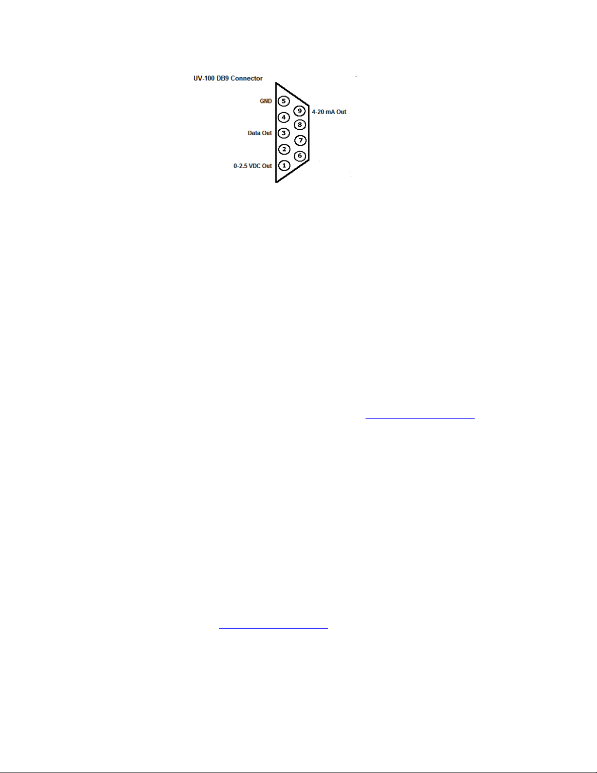
0-2.5 volts C: (2.5V = ull ppm scale) Pins 1 and 5 o the RS-232 connector.
4-20 mA: (4 mA = 0 ppm, 20 mA = ull scale) Pins 9 and 5 o the RS-232 connector.
ata output via RS-232 Connector: This output is ozone concentration in PPM,
temperature, pressure, and time and date sent in ASCI via the RS-232 connector on the
rear panel o the UV-100. This can be directly connected to the serial COM port o many
computers.
irect USB Output: Data is also available via the USB port on the rear panel o the UV-
100. A CD disc with drivers or Windows Vista, Windows XP and Windows 7 are
included in this shipment or can be emailed to you by our tech support department. Set
up is shown in Appendix B. Output is shown as ozone concentration (PPM), temperature
in degrees K, pressure in Torr, and time and date. Some computers will ind an already
existing USB driver installed that will accept the UV-100 USB output. Due to the many
variations o operating systems in use, i you have problems installing or using the
drivers on our disc, contact Tech Support at Eco Sensors ([email protected]).
Set Point Relay Contacts: A wiring plug is provided to enable component control via
relay. Re er to Appendix X or application examples using this relay.
SERVICE AN MAINTENANCE
There are no user serviceable parts in this instrument. Opening the enclosure will void
the warranty.
Filter/Input: The input sample tubing ilter is recommended or any operational
environment. A length o Tygon TE-200 Te lon coated tubing and a disposable
micromesh disk ilter is provided. It is recommended that the input ilter is replaced at 6
month intervals, more o ten in dusty and more complex environments.
In severe condensing humidity environments a small moisture trap may be needed on
the input to protect the UV-100’s internal tubing rom condensing moisture internally.
AC A APTER
For use in North America and other areas with 120 V 60 HZ, the Eco Sensors P-20
adapter should be used. For other areas adapters should be purchased locally that it
7

local wall sockets and con orm to local codes. The output should be 12 volts DC
unregulated, 500 mA. The plug to our instrument should it a 5.5/2.5 mm socket with the
center pin +. For urther details see our Tech Note P-102.
SPECIFICATIONS
Sensor: Narrow band ilter to UV detector at 254 nm.
Sensitivity: First responds at approximately .01 ppm
Accuracy: 0-100 ppm, 2 %. 100-999 ppm 5%
Response time: Within one minute o when gas reaches the sensor
Temperature and humidity range: 10-40 deg C and 0-80% relative humidity.
Fuse: Sel -resetting. Not user replaceable.
Filter (sample inlet): 30 micron disposable.
Supply voltage required: 12-24 volts DC, 500 mA.
Size of instrument (H W D): 95 X 210 X 216 mm (3 3/4" X 8 1/4" X 8 1/2").
Weight of instrument: 2.1 kg (4.7 lbs.).
PRECAUTIONS
• Allow at least 30 minutes warm-up.
• Read all instructions in this manual.
• Keep instrument dry. Never let water or other liquids into the sensor.
• Do not drop the instrument or subject it to continuous vibration.
• Do not store in high levels o dust.
• Do not clean the instrument with cleaning chemicals or solvents. Clean it with a damp
cloth.
• Do not operate near heavy aerosols (spray) usage or where oxygen is being
administered.
• Call a quali ied electrician i you have any doubts about voltages, currents, electrical
practice, etc.
• While not necessary or typical uses, or highest precision results in electrically noisy
locations, the instrument should be grounded to earth to achieve maximum stability.
WARRANTY
This product is warranted against de ects in materials and workmanship or one year
ollowing the date o purchase by the original owner. This warranty does not include
damage to the product as a result o misuse, accident, damage, modi ications or
alterations, and it does not apply i the instructions in this manual are not ollowed.
I a de ect develops during the warranty period, Eco Sensors at its election will repair the
instrument or replace it with a new or reconditioned model o equivalent quality. In the
event o replacement with a new or reconditioned instrument, the replacement unit will
continue the warranty o the original unit.
To return the instrument contact your distributor, or call Eco Sensors at (800) 472-6626
or e-mail at [email protected] to receive return instructions and a Return Material
Authorization (RMA) number. Except as provided herein, Eco Sensors makes no
warranties, express or implied, including warranties o merchantability and itness or a
particular purpose. Eco Sensors shall not be liable or loss o use o this instrument or
8

other incidental or consequential damages, expenses or economic loss, or claims or
such damage or economic loss.
RECORD YOUR SERIAL NUMBER HERE__________________________________
KEEP THIS MANUAL AND WARRANTY FOR YOUR RECORDS.
Eco Sensors is a registered trademark o Eco Sensors, Inc.
© Eco Sensors, Inc. 2004. Revision 08/11
For brochures, application and tech notes, and other use ul in ormation, visit our
extensive website at www.ecosensors.com. E-mail us at [email protected].
APPEN IX A
RS232 SERIAL DATA SETUP AND READOUT EXCLUDING WINDOWS 7
1. Open HYPERTERMINAL rom the ACCESSORIES older o the PROGRAMS
directory.
9
2. You will be asked or a CONNECTION DESCRIPTION. Click OK.
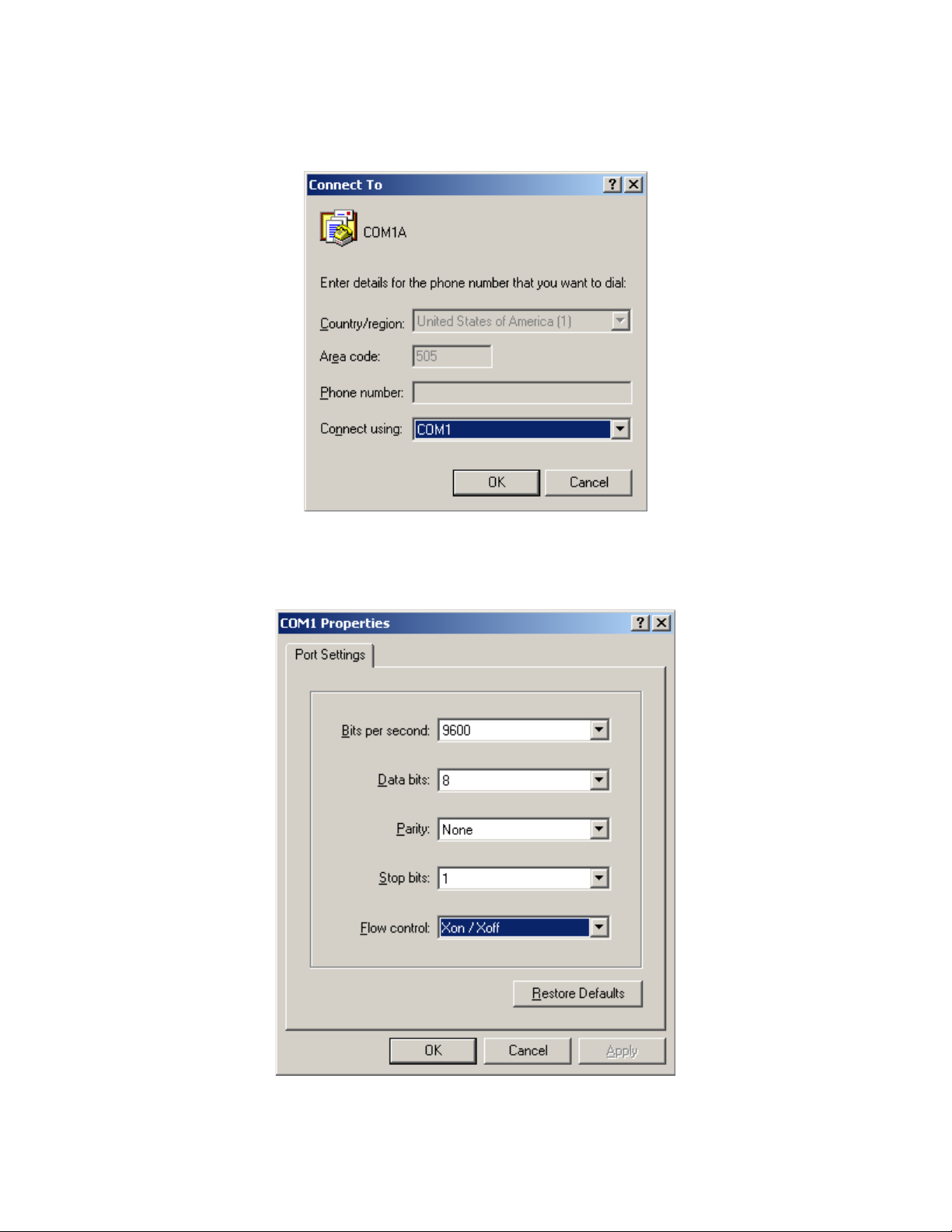
3. Choose which port you will use to connect to the computer. The de ault serial COM
port on most PC computers is COM1. Click OK.
4. Enter PORT SETTINGS as above: Bits per second – 9600 data rate, Data bits - 8,
10

Parity - None, Stop bits - 1, Flow control - XON/XOF. Click OK.
RS232 SERIAL DATA SETUP AND READOUT FOR WINDOWS 7
Windows 7 does not include a terminal program. Third party shareware programs such
as TerraTerm are available rom websites such as www.download.com . These
programs vary in operation slightly but the procedure is approximately the same as
above.
I a Windows XP installation disk is available, Hyperterminal can be trans erred to
Windows 7. Copy hypertrm.exe rom Program Files\Windows NT directory and
hypertrm.dll rom the Windows\System32 directory o the Windows XP disk to
APPEN IX B
UV-100 USB DIRECT CONNECT PROCEDURE
Items:
• UV-100
• USB Cable
• PC Computer with Windows 2000, Vista or XP
• USB to UART Driver Disk
1. Install USB to UART Driver Disk in the computer’s CD ROM drive.
2. With the UV-100 o , attach USB cable rom UV-100 to a USB port on the computer.
3. Turn on UV-100.
4. The computer should recognize the USB connection
5. Select the “Install rom a speci ic location” option.
6. Navigate to the CD ROM drive.
11
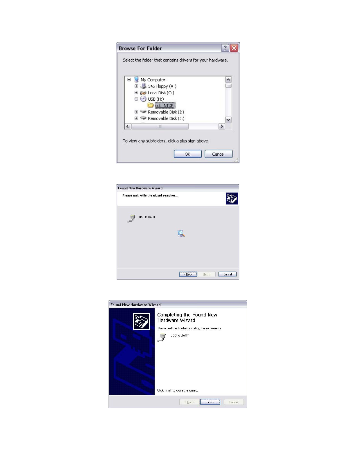
7. Run the Installation wizard.
8. Finish the driver installation.
12
9. Re er to Appendix A or connection steps via Hyperterminal or other terminal
programs.
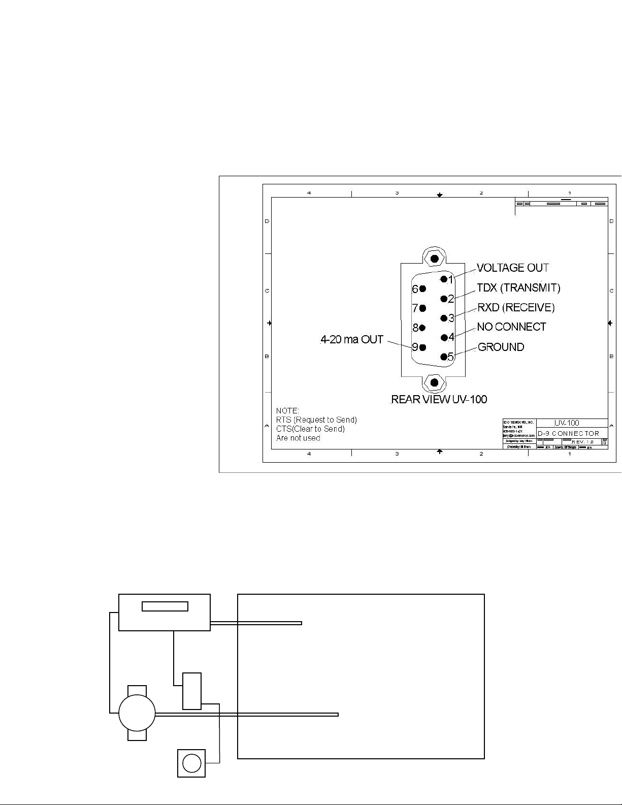
APPEN IX C
PINOUT OF DB9 CONNECTOR
APPEN IX
APPLICATION EXAMPLES
Here are 3 widely used examples installed by many users o the UV-100. These are
shown for reference only; or more details contact Eco Sensors Tech Support.
REMEDIATION EXAMPLE
Ozone’s cleaning and disin ecting properties are well known. Its ability to break down
bacteria and a wide range o contaminants with almost no residue is just beginning to be
used in real-world applications. The ollowing is an example o one o Eco Sensor’s
Customer setup to remove mold rom rooms and combined spaces in looded homes:
Items:
UV-100
Ozone generator(s) (UV 550 Pro or similar)
Power relay (s) or generator and an (optional)
Indicator light or OSHA limit
4-20 mA current loop
To destroy mold the space is held at a very high Ozone level or a predetermined
amount o time. The generator is controlled using the set point relay on the back o the
UV-100 to hold Ozone.
A ter the Ozone “dwell” interval is complete, generator power is shut o or UV-100
generator ON level is set to zero. Over the course o a ew hours the Ozone will decay to
zero. In this particular installation an indicator light was tied to the 4-20 mA output to give
an “all clear” indication when the space was reading under the OSHA immediate limit o
0.3 PPM. 4-20 mA scale is set to 4 mA = 0 PPM, 20 mA = 1 PPM.
COL CON ENSING EXAMPLE
Items:
UV-100
Tygon SE-200 Te lon lined tubing, length variable
Small moisture trap
13
Remediation Space
UV-100
Ozone
Generator
4-20mA
Current
Loop
Sa ety
Indicator
Relay Output 4-20 mA Output

Ozone generator (i Ozone control is required)
In some applications the environment under measurement is outside the temperature
and/or humidity range o the UV-100. Several methods can used to shield the UV-100
rom theses extremes.
The UV-100 is kept isolated by being outside the cold space and by using a long length
o inlet tubing, the majority o which coiled outside the cold space. This allows or the
inlet sample to be warmed to an acceptable level be ore measurement.
Condensation rom the temperature change is eliminated using a small moisture trap
spliced into the inlet line.
Due to the extra length o inlet tube and moisture trap, o sets will need to be made or
measurements. The reading will be delayed depending on the length o tube, as much
as an extra minute or more. Testing with high Ozone pulses can determine this delay.
The reading will also be attenuated as much as 5% due to the inlet length and loss rom
the moisture trap.
LONG TERM ATA LOGGING EXAMPLE
The internal memory or data storage or the UV-100 is limited to approximately 36
hours. For long-term logging the best method is voltage data logging using the Eco
Sensors DL-3 and the 0-2.5 VDC output on the 9 pin connector.
Items:
UV-100
Computer
Eco Sensors DL-3 Voltage Data Logger
D9 cable with pin breakout
HOBO Data Logger So tware
Wiring:
A DB9 connector with discreet wiring will be needed to connect the DL-3. The 0-2.5V
output on the D9 Connector (Pin 1 +V, Pin 5 GND) is connected to a mini stereo jack to
one channel o the DL-3. Custom DL-3 voltage cables can be purchased rom Eco
Sensors as an option with the DL-3.
The DL-3 has 4 channels that could be used to log multiple UV-100’s or other
parameters such as temperature and relative humidity.
UV-100 Scaling:
Set the 0-2.5 VDC scale to the anticipated maximum Ozone level in the measurement
environment. This will give the highest possible resolution to the Voltage output or
logging.
14
Ozone
Generator
UV-100
Cold/Hot
Ozone Space
Moisture
Trap
Cooling/Warming
Coil

DL3 Scaling:
Install the the HOBOware so tware supplied with the DL-3 and connect the DL-3 to a
computer using the USB cable. Set input type or channel 1 to Voltage, scale to 0 VDC =
0 PPM and 2.5 VDC = to the scale value in the UV-100. For urther details about
HOBOware setup contact technical support.
APPEN IX E
THEORY OF OPERATION
The Eco Sensors Ozone Monitor is designed to enable accurate measurements o
indoor ozone over a wide dynamic range extending rom a limit o detection o .01 ppm
by volume (ppmv) to an upper limit o about 1,000 ppm based on the well established
technique o absorption o ultraviolet light at 254 nm. The Ozone Monitor is light weight
(4.7 lb., 2.1 kg.) and has low power consumption (≈5 watt) relative to conventional
instruments and is there ore well suited or applications such as:
• Industrial hygiene monitoring where ozone may be present in the workplace.
• Control o ozone generators and systems.
• Research and quality checking o ozone emitting equipment.
• Monitoring high ozone concentrations such as process o -gassing.
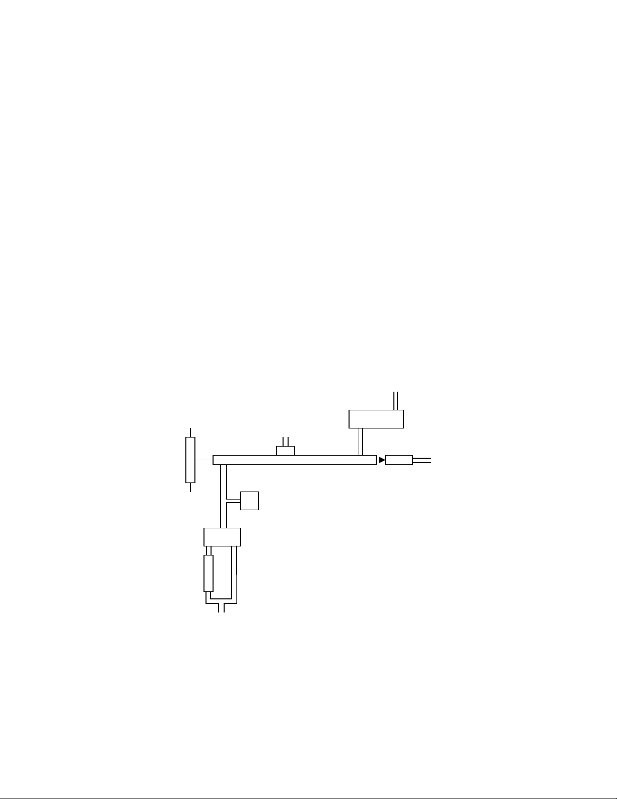
Theory of Operation
Absorption o UV light has long been used or measurements o atmospheric ozone with
high precision and accuracy. The ozone molecule has an absorption maximum at 254
nm, coincident with the principal emission wavelength o a low-pressure mercury lamp.
Fortunately, ew molecules ound at signi icant concentrations in the atmosphere absorb
at this wavelength. However, inter erences, such as organic compounds containing
aromatic rings, can occur in highly polluted air.
Figure 1 is a schematic diagram o the ozone monitor. Ozone is measured based on the
attenuation o light passing through a 6.2 cm long absorption cell itted with quartz
windows. A low-pressure mercury lamp is located on one side o the absorption cell, and
a photodiode is located on the opposite side o the absorption cell. The photodiode has a
built-in inter erence ilter centered on 254 nm, the principal wavelength o light emitted by
the mercury lamp. An air pump draws sample air into the instrument at a low rate o
approximately 1 L/min. A solenoid valve switches so as to alternately send this air
directly into the absorption cell or through an Ozone scrubber and then into the
absorption cell. The intensity o light at the photodiode is measured in air that has
passed through the Ozone scrubber (Io) and air that has not passed through the
scrubber (I). Ozone concentration is calculated rom the measurements o Io and I
according to the Beer-Lambert Law:
15
Where l is the path length (6.2 cm) and σ is the absorption cross section or ozone at
254 nm (1.15 x 10⁻¹⁷ cm2 molecule-1 or 308 atm-1 cm-1), which is known with an
accuracy o approximately 1%. The Eco Sensors instrument uses the same absorption
cross section (extinction coe icient) as used in other commercial instruments.
The logarithm o equation 1 is approximated in the microprocessor o the instrument with
su icient accuracy to provide ive orders o dynamic range; ozone mixing ratios are
measured up to 1,000 ppmv, as compared to 1 ppmv or most commercial ozone
instruments.
The pressure and temperature within the absorption cell are measured so that the ozone
concentration can be expressed as a mixing ratio in parts-per-million by volume (ppmv).
In principle, the measurement o ozone by UV absorption requires no external
calibration; it is an absolute method. However, non-linearity o the photodiode response
and electronics can result in a small measurement error. There ore, each instrument is
compared with a NIST-traceable standard ozone spectrophotometer in the laboratory
over a wide range o ozone mixing ratios. These results are used to calibrate the Ozone
Monitor with respect to an o set and slope (gain or sensitivity). Calibration data is
supplied with the instrument. It is recommended that the instrument be recalibrated at
least once every year and pre erably more requently. The o set may dri t due to
temperature change or chemical contamination o the absorption cell. An accurate o set
correction can be measured rom time to time using the ozone scrubber ("zero ozone
ilter") available or use with the instrument.
16
Hg Lamp
Temperature Sensor
Air Pump
PhotodiodeAbsorption Cell
Pressure Sensor
Solenoid Valve
Ozone
Scrubber
Air Inlet
Basic UV Instrument System

OPTIONS Available or UV-100
Pelican case PN 20-0598 $ 180.00
Hi E iciency Sample Line Filter and Housing PN FLTRS(LARGE) $ 126.00
Hi E iciency Sample Line Filter Elements 10pcs PN FILTERPAK(LARG) $ 63.00
Heavy Duty External Pump(replaces internal pump) PN EXT PUMP(HD) $ 440.00
C Type Power Plug 240 VAC 50Hz Adapter $ 75.00
17
Other manuals for UV-100
1
Table of contents
Other ECO Sensors Measuring Instrument manuals


