ECO Sensors A-22 User manual

11-07
ECO SENSORS, INC.
OZONE SENSOR AND MONITOR
Model A-22
INSTRUCTIONS FOR USE
Sensor
A-22
SM-X precalibrated
sensor module.
Replacement easily
sent by mail.
Data and
power jacks
on the side.
Rubber “boot” to
protect against
mechanical damage.

2
GENERAL
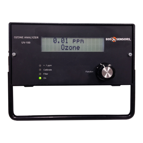
The Eco Sensors A-22 is a general purpose ozone sensor and monitor. It is designed for rugged
indoor use, factories, pilot plants, process facilities and general sensor and monitoring uses. It
uses the same precalibrated sensor modules as our OS-4 permanent monitor and controller. The
internal signal processing is done by digital microprocessors. The A-22 automatically selects the
.030-1.999 or 2.00-20.00 ppm range as required. Its outputs are USB, 4-20 mA, 0-2 VDC and a
digital display that can be back lighted. The plug-in replaceable sensors are precalibrated. The
user can select continuous reading, or the maximum, average or minimum over a period of time.
The hard rubber outer case helps protect the instrument from mechanical shocks. It has a tilt
stand which can also be reconfigured to a hanging hook.
The instrument can be powered by its internal rechargeable batteries or by its AC
charger/adapter.
Do not open or service the instrument or replace the sensor module when the instrument
is turned on. This will damage the sensor calibration memory and possibly other circuits
in the instrument.
The instrument is conditionally warranted for one year. Save a copy of your purchase document
as a proof of purchase and date, and read the warranty statement at the end of this manual.
OPERATION
First, verify that the instrument is working as received. Turn the function switch to on. Digits
should appear on the display and assuming no ozone is present, should stabilize at 0.000. If the
display does not activate, the batteries may have discharged during shipping and storage.
Charge the batteries by rotating the control to the off position. Plug in an AC adapter/charger to
the jack located on the right side of the instrument, and charge overnight.
In order to burn off any chemicals that the sensor may have absorbed during shipping and
storage, you should let the A-22 run with power on and the sensor module connected for 1 hour
before response testing or overnight before the first use on site.
After the instrument has warmed up, you can read the
output with the range of .030-1.999 or 2.00-20.00
automatically selected by the A-22. The output will
also appear as RS-232 at the USB port, 0-2 V for
data logging and 4-20 mA for PLCs.
To read maximum, minimum or average of a data
stream, first turn the control to Reset for a few
seconds until the display reads 0.000. Then, turning
the control switch to Max,Avg or Min will give
corresponding readouts of the data stream maximum value, average value or minimum value
since the instrument was reset. Turning the control to Reset again destroys all previous data.
Maximum, average and minimum data are not stored in memory or outputted from the instrument.

3
The display light button is near the rotary switch control. Pushing that button will activate a
backlight on the LCD display which will remain on for 6 seconds. It will only be visible when the
instrument is in a dark area and should not be used excessively because it creates a large drain
on the batteries.
Note: For best results in moving air, turn the instrument sideways (at 90 deg angle) to the air
flow. Air flow into the sensor will cool it, lowering its temperature, and changing the reading.
CHARGING THE BATTERIES
For the quickest charge (4-5 hours) use a 12-24 VDC adapter, 1 A. A 300 mA adapter, which is
more commonly available, will charge the batteries in about 8 hours (over night). The batteries
should last for 16-24 hours of continuous use (2-3 work days).
CALIBRATION
The A-22 uses a calibration concept that is somewhat novel: The ozone sensor is mounted on a
sensing board, called the SM-X, includes a microprocessor and EEPROM memory. The exact
calibration curve for that particular ozone sensor is burned into the EEPROM. The A-22 host
instrument adjusts the sensor readings for temperature and relative humidity based on data sent
from the sensor module.
In most cases, it is probably cheaper and faster to replace the SM-X sensor board with a freshly
calibrated one than to send the current old one back for recalibration. Also the SM-X board can
NOT be recalibrated in the field. It can only be done by a special computer at Eco Sensors, Inc. It
is more expensive to recalibrate the SM-X than to by a new precalibrated one because the
original SM-Xs are calibrated with semiautomatic equipment.
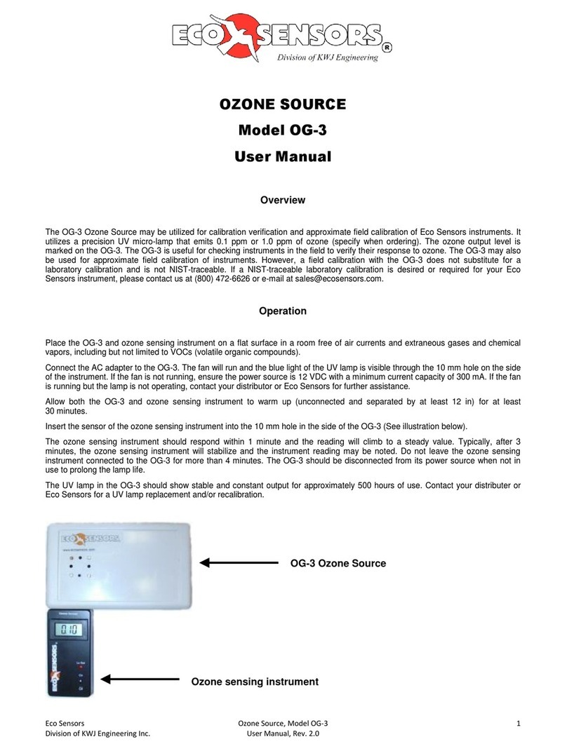
The SM-X calibration can be checked by the Eco Sensors OG-3 calibration checker. The
calibration is within 15% over the sensor's range. For the OG-3 to mate with the A-22 sensor, it
will be necessary to remove the orange protective “boot” that surrounds and protects the
instrument.
OUTPUTS TO EXTERNAL EQUIPMENT
The A-22 has a variety of outputs to external equipment. Referring to the jacks on the right side
of the instrument, these are:
AC Adaptor USB 2 Circuit output jack:
Tip: 0-2 VDC
Ring: 4-20 mA

4
Connecting the USB output to your computer is shown in Appendix B. This is designed for
Microsoft 2000and XP. It may work on some other Microsoft operating systems. Some computers
will find a deriver in their system that works with our USB. Otherwise, drivers can be emailed to
you by our tech support department reached at tech@ecosensors.com.
MOUNTING STAND
The A-22 outer case includes a removable stand which can be used two ways:
As tilt stand Hung from wall hook
SERVICE AND MAINTENANCE
Do not attempt to do board level repairs or microprocessor programming yourself. This will void
the warranty. We recommend checking the calibration monthly and replacing the sensor module
annually. General repairs should be done at the factory or by an Eco Sensors authorized service
representative.
Calibration of the sensor on its board (SM-X) is done by computer in a special laboratory at the
factory. Therefore in most cases it is lowest cost to replace the SM-X board than to request that it
be recalibrated.
Instruments with problems during the warranty period should be returned as system (OS-4 and
SM-4) to the factory or authorized service representative for diagnosis and repair.
AC ADAPTER
For use in 120 V 60 HZ areas, the Eco Sensors P-20 adapter should be used. For other areas
adapters should be purchased local that fit local wall sockets and conform to local codes. The
output should be 12 volts DC unregulated, 300-500 mA. For fast charge, the adapter output
should be 1 amp. The plug to our instrument should fit a 5.5/2.5 mm socket with the center pin +.
For further details see our Tech Note P-101.
SPECIFICATIONS
Sensor: Heated metal oxide semiconductor.
Ranges. 0-1.999 ppm and 2.00-20.00 ppm autoselected.
Sensitivity: First responds at .01 ppm

5
Response time: Within one minute of when gas reaches the sensor.
Temperature and humidity range: 0-40 deg C and 0-80% relative humidity.
Supply voltage required: 8-24 volts DC, 300-500 mA. Ground -.
Adapter plug: 5.5 mm/2.5 mm female, center +.
Size of instrument: 219 (H) X 111 (W) X 61 mm (D) (8.63" X 4.38" X 2.38").
Weight of instrument: 745 grams (1.64 lbs.).
SAFETY FEATURES
Sensor: Heated element is flame arrestor protected.
Electrical: (a) Circuits operate at 12-24 volts (b) Self-resetting fuse to protect against excess input
current flow. (d) Overvoltage protection diode barrier to protect against supply voltage surges,
spikes, overvoltage, and reverse polarities.
PRECAUTIONS
xAlways have the function switch in the off position with the adapter disconnected when
servicing the instrument or changing the sensor module.
xAllow at least 1-4 hours warm-up for functionality testing and 24 hours warm-up for
operational use.
xRead all instructions in this manual.
xKeep instrument dry. Never let water or other liquids into the sensor.
xDo not drop the instrument or subject it to continuous vibration.
xDo not store in high levels of dust.
xDo not clean the instrument with cleaning chemicals or solvents. Clean it with a damp
cloth.
xDo not operate near heavy aerosols (spray) usage or where oxygen is being
administered.
xCall a qualified electrician if you have any doubts about voltages, currents, electrical
practice, etc.
xDo not operate the instrument or rely on its readings where there are high concentrations
of:
- Chlorine or other halogen compounds
- Sulfur compounds
- Strong VOCs such as solvent vapors.
- Silicone compounds such as RTV.
- Urine residues and ammonia compounds
- Acid gases such as sulfuric acid or nitric acid fumes.
xKeep at least a meter above fruit in food storage applications to avoid the negative
influence of ethylene ripening agent emitting from the fruit.
When in doubt, operate the instrument in your worst case conditions for at least 24 hours to see if
it will operate properly.

6
WARRANTY
This product is warranted against defects in materials and workmanship for one year following the
date of purchase by the original owner. This warranty does not include damage to the product as
a result of misuse, accident, damage, modifications or alterations, and it does not apply if the
instructions in this manual are not followed.
If a defect develops during the warranty period, Eco Sensors at its election will repair the
instrument or replace it with a new or reconditioned model of equivalent quality. In the event of
replacement with a new or reconditioned instrument, the replacement unit will continue the
warranty of the original unit.
If the product should become defective during the warranty period, please return it through your
return instructions and a Return Goods Authorization (RGA) number.
Except as provided herein, Eco Sensors makes no warranties, express or implied, including
warranties of merchantibility and fitness for a particular purpose. Eco Sensors shall not be liable
for loss of use of this instrument or other incidental or consequential damages, expenses or
economic loss, or claims for such damage or economic loss.
This warranty gives you specific legal rights, and you may also have other rights which vary from
state to state.
RECORD YOUR SERIAL NUMBER HERE__________________________________
KEEP THIS MANUAL AND WARRANTY FOR YOUR RECORDS.
Eco Sensors is a registered trademark of Eco Sensors, Inc.
© Eco Sensors, Inc. 2007. A-22 REV 1, SM-X, Manual rev 2/07
For brochures, application and tech notes, and other useful information, visit our extensive

7
APPENDIX A
REPLACING THE SENSOR MODULE
1 - Always have the function switch in the off position with the adapter disconnected when
servicing the instrument or changing the sensor module.
2 - Remove instrument from the orange boot and then
remove the sensor module access cover.
3 - Locate the sensor module board. Care note its
location on the main board. It can be unplugged
by pulling it up.
4 - Select a replacement sensor module holding it
by the edges as shown to avoid static electricity
being transferred from your fingers to the
delicate semiconductor chips.
5 - Plug it into the main circuit board so that all the pins
on the main board fit into socket holes on the
module board. The replaced sensor module
should appear as in the photo for step 3.
6 – Replace the sensor module access cover.
7 – Replace the orange “boot.”

8
8 – Power the instrument and after 15 minutes check to see if the sensor seems to be responding
to ozone.
9 – Leave the instrument on for at least an hour and preferably overnight to burn-in the new
sensor (to restore it to its original calibration by burning off VOCs which could be absorbed by the
sensor during storage).

9
APPENDIX B
A22 USB Direct Connect Procedure
Items:
xA22
xUSB Cable
xPC Computer with Windows 2000 or XP
xUSB to UART Driver Disk
1. Install USB to UART Driver Disk in the computer’s CD ROM drive.
2. With the A22 off, attach USB cable from A22 to a USB port on the computer.
3. Turn on A22.
4. The computer should recognize the USB connection
.
5. Select the “Install from a specific location” option.
6. Navigate to the CD ROM drive.

10
7. Run the Installation wizard
8. Finish the driver installation.

11
A22 Communication with the Computer
1. Open HyperTerminal in Windows.
2. Title Connection “A22”.

12
3. Set communication parameters as shown. The COM port will be the highest one. i.e,
COM6
4. The A22 will output at 1 second intervals.
A22 Reading 1.296 PPM:
Table of contents
Other ECO Sensors Measuring Instrument manuals
