Eco-Smart EcoWave EcoTouch Owner's manual

EcoWave Featuring the EcoTouch
Installation, Operation& Maintenance Guide

Table of Contents
Table of Contents ............................................................................................................... i
Introduction......................................................................................................................1
Conventions Used in this Guide.............................................................................................1
The EcoSmart Energy Management System ...............................................................................2
Regulatory Compliance ......................................................................................................2
Overview: EcoWave Remote Thermostat/Controller Package..........................................................3
EcoSource ........................................................................................................................5
Wiring..........................................................................................................................5
High/Low Voltage Options ..................................................................................................6
High Voltage Installation ....................................................................................................6
Low Voltage Installation................................................................................................... 14
Instructions Common to All Three Low Voltage Options .............................................................. 21
EcoTouch....................................................................................................................... 24
EcoTouch Location Planning .............................................................................................. 24
Installation .................................................................................................................. 26
EcoTouch Guest Screen Controls & User Interface..................................................................... 29
Device Association ............................................................................................................ 31
Pair EcoTouch with EcoSource............................................................................................ 31
EcoTouch Configuration Changes ........................................................................................... 32
Change Channel ............................................................................................................ 32
Unpair EcoTouch............................................................................................................ 32
Activate “Display Mode” Option.......................................................................................... 32
System Status Screen ...................................................................................................... 32
Regular Maintenance ......................................................................................................... 33
Troubleshooting ............................................................................................................... 34
Troubleshooting ............................................................................................................... 35
Troubleshooting ............................................................................................................... 36
Index ......................................................................................................................... 37
Appendix A .................................................................................................................. 39
EcoWave Featuring EcoTouch IO&M Guide Telkonet,Inc.
For Use with Firmware Version 2.x 20800 Swenson Drive,Suite 175
Table of Contents Waukesha, WI 53186
Revision 2 (800) 380-9640
Page i www.telkonet.com

Company Headquarters:
Customer Support:
EcoSmart Sales:
Telkonet, Inc.
(800) 380-9640
(888) 703-9398
20800 Swenson Drive
Email:
Email
Suite 175
ecosmartsupport@telkonet.com
sales@telkonet.com
Waukesha, WI 53186
P (414) 223-0473
F (414) 258-8307
EcoWave Featuring EcoTouch IO&M Guide Telkonet,Inc.
For Use with Firmware Version 2.x 20800 Swenson Drive,Suite 175
Table of Contents Waukesha, WI 53186
Revision 2 (800) 380-9640
Page ii www.telkonet.com

Introduction
Conventions Used in this Guide
This is an informationaltip,usedto convey
relevant but not necessarily urgent
information.
This is a warning,usedtoconvey important
information.
This is a strong warning,usedtoconvey
urgent andoftensafety-relatedinformation.
ChapterNames
Mainchapters inthis manualwill haveheadings inlargegreen
font as shownabove.Mainchapter namesalsoappear inthe
footer.
Sub-Chapter Names
Withinthemain chapterswill be relevant sub-chapters,which
arepresentedwith bold,black headings as shown above.
Footers
Footers containthedocument name,chapter name,document
versionnumber andpagenumber, as shownhere:
Procedure: Steps Described Here
ProceduralSteps are indicatedas suchintheheading,which
begins withtheword,“Procedure:”asshownabove.Thesteps
areoutlined as shownin the following example:
Step 1 Navigate totheConfig Menu> Alert Setup.
Step 2 Click the Add New AlertTrigger buttonin
thetopleft corner oftheAlert SetupScreen.
Step 3 Enter a descriptive Alert Name.
IntroducingaNew Screen
Whena screen is introduced, a screen printis provided. Below
the screenprint willbe its locationand anexplanationof the
screen’s intendedpurpose as shownin this example:
Screenand TabNames
ScreenandTab names areunderlined, as shownin this example:
The ThermostatStatusScreenshowsall rooms and
their statusinformationat aglance.
FieldNames
Field names appear in bold font; field explanations appear next
tothe field name as shownin this example:
Device Select thedevicetype.
Position The order inwhich attacheddevices are
associated.
MAC Address MAC address of the attached device.
Field SelectionChoices
Fieldselectionchoices are in italics as shownin this example:
Select theAlerting DeviceTypefromthedropdown
menu. Choices are:AllThermostats,AllPipeSensors,
SingleDevice andOutdoor Temperature.
The “>” Symbol
The ">" symbolis used to describe a menu choice and command
selection.For example:
ConfigurationMenu >Alert Setupmeans click on the
ConfigurationMenu, thenclick on Alert Setup.
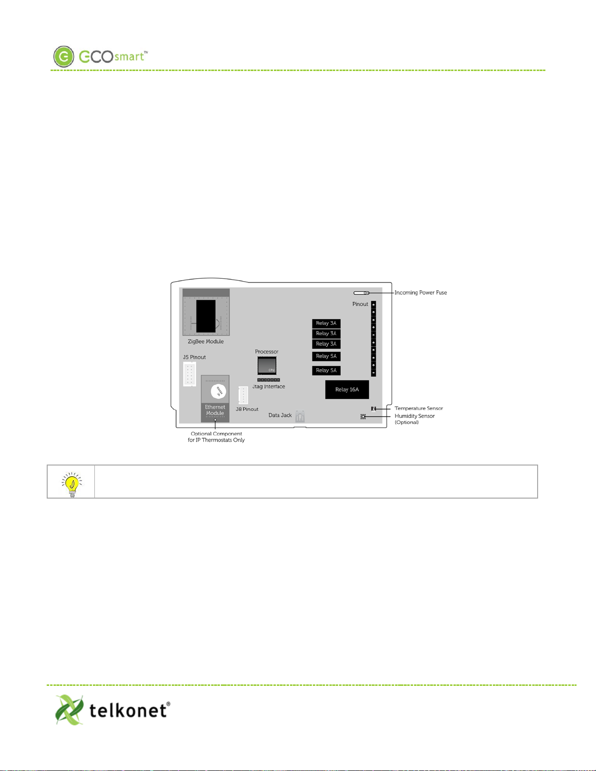
Tables
Tables provide visualpresentations ofrelateddata such as
hardwarecomponentsandexplanationsas showninthis
example:
Pin Labelon Backplate Function
1 iaculis Lorem ipsum dolor sit
amet.
2 velit
Fusce pharetra risus eu
nibh consequatvolutpat.
3 sagittis Uisque laoreet augueeu
elit dignissimfeugiat.
Troubleshooting
Assistancewithtroubleshooting beginswiththeredheader as
shownabove.
EcoWave Featuring EcoTouch IO&M Guide Telkonet,Inc.
For Use with Firmware Version 2.x 20800 Swenson Drive,Suite 175
Introduction Waukesha, WI 53186
Revision 2 (800) 380-9640
Page 1 www.telkonet.com

EcoWave Package Overview
The EcoSmartEnergy Management System
The EcoSmart Energy Management System reduces HVAC energy consumption without interfering with occupant
comfort.
EcoSmart thermostats such as the EcoTouch automatically learn and adapt to the heating and cooling patterns
of each room. For example, a room on the east side of a building will receive direct sunlight in the morning and
will either need less HVAC heating or more HVAC cooling. However, as the day progresses, the room will need
more HVAC heating or less HVAC cooling as it moves into the shade. An EcoSmart thermostat will continually
monitor the room, learn its patterns, and adjust its heating and cooling profiles accordingly.
EcoSmart thermostats also learn and adapt to occupant schedules. When a room is unoccupied, the EcoTouch
will enter an energy saving mode, allowing the room to drift away from the desired set point. During this drift
period, the thermostat will operate the HVAC unit less often, reducing energy costs. When the room becomes
occupied again, the RecoveryTime™ technology built into each EcoTouch will return the room to the set point
without occupant interaction.
The EcoWave is available in several configurations to address specific requirements of multiple applications
including hotel, classroom, office, university dormitory, military residence hall, retail, public area, convention
center, and a wide variety of commercial and industrial spaces.
The firmware of standalone EcoWave thermostats is identical to the firmware of networked versions.
Standalone Thermostats can be networked by adding a network module to the base units at any time.
Programming features used during installation, maintenance, and troubleshooting are available in the on-
screen Maintenance Menu.
Regulatory Compliance
FCC ID: XV6SS6560
This device complies with Part 15 of the FCC Rules. Operation is subject to the following two conditions: (1)
this device may not cause harmful interference, and (2) this device must accept any interference received,
including interference that may cause undesired operation.
This equipment has been tested and found to comply with the limits for a class B digital device pursuant to
part 15 of the FCC Rules. These limits are designed to provide reasonable protection against harmful
interference in a residential installation. This equipment generates, uses and can radiate radio frequency
energy and if not installed and used in accordance with the instructions, may cause harmful interference to
radio communications. However, there is no guarantee that interference will not occur in a particular
installation. If the equipment does cause harmful interference to radio or television reception, which can be
determined by turning the equipment off and on, the user is encouraged to try to correct the interference by
one or more of the following measures:
•Reorient or relocate the receiving antenna.
•Increase the separation between the equipment and the receiver.
•Connect the equipment into an outlet on a circuit different from that to which the receiver is
connected.
•Consult the dealer or experienced radio/TV technician for help.
EcoWave Featuring EcoTouch IO&M Guide Telkonet,Inc.
For Use with Firmware Version 2.x 20800 Swenson Drive,Suite 175
Waukesha, WI 53186
Revision 2 (800) 380-9640
Page 2 www.telkonet.com

EcoWave Package Overview
In order to maintain compliance with FCC regulations, shielded cables must be used with this equipment.
Operation with non-approved equipment is likely to result in interference to radio and TV reception. The user
is cautioned that changes and modifications made to the equipment without the approval of the manufacturer
could void the user’s authority to operate the equipment.
To satisfyRF exposure requirements, this device and its antennas must operate with a separation distance of at
least 20 cm from all persons and must not be co-located or operating in conjunction with any other antenna or
transmitter.
Overview:EcoWave Remote Thermostat/Controller Package
The EcoWave package is comprised of two hardware components as shown below. Together they form a
wireless programmable controllable thermostat. It can be easily installed on packaged terminal air
conditioners, fan coils, heat pumps, split systems,and more. Withsoftware-based relay control and fan speed
configuration, programming setup is simple and fast.
EcoTouch
•Display unit
•Place in optimum location for temperature measurement and
ease of occupant use
EcoSource
•HVAC Controller
•Install in or on HVAC unit
•Accepts association with 15 total compatible wireless devices
•Each compatible wireless device can be associated to
multiple EcoSources
Accomodates a Variety of Configurations
EcoWave Featuring EcoTouch IO&M Guide Telkonet,Inc.
For Use with Firmware Version 2.x 20800 Swenson Drive,Suite 175
Waukesha, WI 53186
Revision 2 (800) 380-9640
Page 3 www.telkonet.com

EcoWave Package Overview
The EcoWave Package can be configured for many different HVAC
scenarios. For example:
One EcoTouch can control multiple HVAC systems, each equipped
with an EcoSource, but all directed by a single EcoTouch display
unit. This type of installation reduces the complexity of running
multiple HVAC units in a single large space and eliminating the
potential of opposing modes forcing equipment to compete
against each other.
Multiple EcoTouches can control one HVAC system, equipped
with one EcoSource.
The wiring interface conforms to industry standards. Telkonet
can develop specific wiring diagrams, if a complete specification
is provided for the HVAC unit(s) in use at the site.
EcoWave Featuring EcoTouch IO&M Guide Telkonet,Inc.
For Use with Firmware Version 2.x 20800 Swenson Drive,Suite 175
Waukesha, WI 53186
Revision 2 (800) 380-9640
Page 4 www.telkonet.com

EcoSource Installation
EcoSource
Wiring
The EcoSource controller connects to the HVAC system via standard wiring conventions, using 12-277VAC
voltages supplied by the HVAC equipment. The EcoSource can accept three different power sources, which
assist in scenarios where different components (heat, fan) are powered by different voltages. This
simplifies installation on units such as fan coils.
The EcoSource accepts standard thermostat wiring, typically 14-22 AWG. Wiring conventions follow
industry standards; however, it is important to note that the relay configuration is dynamic and can be
modified at the factory or in the field.
Figure 1: Internal View EcoSource
If the EcoSource will be mounted inside a metal HBSC unit or in a room with a large amount of metallic
equipment that may cause RF interference, an external antenna may be necessary.
EcoWave Featuring EcoTouch IO&M Guide Telkonet,Inc.
For Use with Firmware Version 2.x 20800 Swenson Drive,Suite 175
EcoSour ce Waukesha, WI 53186
Revision 2 (800) 380-9640
Page 5 www.telkonet.com

EcoSource Installation
High/Low Voltage Options
High Voltage Installation Option (page 6)
•High Voltage is defined as 48 volt or
greater.
•There are two installation options:
1) JBOX with Vertical Mud Ring Mount:
requires adapter plate as shown in
Figure 2.
2) Factory HVAC Mount
Low Voltage Installation Options (page 14)
•There are 3 options; select based on code
and desired look:
1) Drywall mount: no conduit required;
no JBOX adapter plate required.
2) JBOX with Vertical Mud Ring Mount:
requires adapter plate as shown in
Figure 2.
3) JBOX with Horizontal Mud Ring
Mount: requires wing nut, hole must
be drilled in backplate; no JBOX
plate required.
High Voltage Installation
(For Low Voltage Installation instructions, see page 14).
Mounting Preparation
The back plate type must be defined as low or high voltage prior to shipment.
EcoWave Featuring EcoTouch IO&M Guide Telkonet,Inc.
For Use with Firmware Version 2.x 20800 Swenson Drive,Suite 175
EcoSour ce Waukesha, WI 53186
Revision 2 (800) 380-9640
Page 6 www.telkonet.com

EcoSource High Voltage Installation
CAUTION!
•Weco terminal on-site wiring for high voltage installation is not allowed. You must use the pre-
shipped 16-guage wired backplate provided by Telkonet.
•High voltage installation should only be performed by a qualified heating & air conditioning
contractor or licensed electrician.
•Failure to understand and follow all instructions carefully before installing or operating this
device could cause personal injury and/or property damage.
•All wiring must conform to local and national electrical ordinances and codes.
•Prevent electrical shock, personal injury, and equipment damage: prior to installation or
service, disconnect system’s electric power at main fuse or circuit breaker box.
Figure 2: Telkonet JBOX Adapter Plate
For all high voltage installations a single gang mud ring must be mounted VERTICALLY on a JBOX. A Telkonet
JBOX Adapter Plate (see Figure 2) is required for all JBOX installations.
EcoSource HighVoltage Required Equipment
•EcoSource (P/N: SS6500)
•EcoTouch (P/N: SS6560)
•High Voltage Backplate
•Telkonet High Voltage JBOX Adapter
•Two #6-32 1” screws
•Four #5 ½” coarse thread screws
•Voltmeter
•Level
•Phillips screwdriver
•UL rated insulating tape
•Wire stripper
•Wire cutter
•Wire nuts
EcoWave Featuring EcoTouch IO&M Guide Telkonet,Inc.
For Use with Firmware Version 2.x 20800 Swenson Drive,Suite 175
EcoSour ce Waukesha, WI 53186
Revision 2 (800) 380-9640
Page 7 www.telkonet.com

EcoSource High Voltage Installation
Installation Steps
Step 1 Ensure the JBOX has been installed with a vertical single gang mud ring. See Figure 3.
Figure 3: Vertical Single Gang Mud Ring
Step 2 Turn off power at EcoSource or mounting location using a disconnect switch or breaker
lockout/tag out on appropriate breaker panel.
Step 3 Test that power is off by using a voltmeter.
Step 4 Strip the LINE wire back 0.25 inches.
Step 5 Cap the LINE wire with a wire nut or electrical tape.
Step 6 Cut the COMMON wire so the copper is flush with the insulation.
Step 7 Strip all wires except for COMMON back 0.25 inches.
Reminder: For all high voltage installations, a single gang mud ring must be mounted
VERTICALLY.
Step 8 Determine which end of the adapter plate should be installed as the top, and which end should
be installed as the bottom. As shown in Figure 4, the notch in the main display should be in the
upper left corner, and the smaller, vertical rectangle should be in the lower right corner.
Figure 4: Determine Top & Bottom of Plate
Step 9 Level the high voltage Telkonet JBOX adapter plate and mount to the mud ring with two #6-32
1” screws. See Figure 5.
EcoWave Featuring EcoTouch IO&M Guide Telkonet,Inc.
For Use with Firmware Version 2.x 20800 Swenson Drive,Suite 175
EcoSour ce Waukesha, WI 53186
Revision 2 (800) 380-9640
Page 8 www.telkonet.com

EcoSource High Voltage Installation
Figure 5: JBOX, Mud Ring, Adapter Plate
Step 10 Remove the safety screw from the left side of the thermostat using the hex wrench. See Figure
6.
Figure 6: EcoSource Side View
Step 11 Separate the high voltage back plate from the thermostat: Use a flathead screwdriver to
GENTLY press the tab next to the screw hole to allow the thermostat to pop open.
WARNING: Using too much force can break the tab.
Step 12 Place thermostat backplate against the JBOX adapter plate. The adapter plate and backplate
holes should align if both are correctly oriented.
Thermostat wiring cannot touch or be placed in close proximity to the J7 pins! This can occur if
the wiring enters the thermostat from the J8 hole and is placed diagonally, directly over the J7
pins.
Step 13 Connect each 16-gauge wire (pre-installed on the thermostat’s high-voltage back plate) to the
matching functional wire within the JBOX, using appropriately sized wire nuts or a NEC-
Safety Screw
Tab
EcoWave Featuring EcoTouch IO&M Guide Telkonet,Inc.
For Use with Firmware Version 2.x 20800 Swenson Drive,Suite 175
EcoSour ce Waukesha, WI 53186
Revision 2 (800) 380-9640
Page 9 www.telkonet.com

EcoSource High Voltage Installation
approved electrical connection inside the junction box. If a site-specific wiring diagram was
provided, refer to this for wiring. If no diagram was provided, refer to Figure 7.
. (If controlling proportional valve or ECM fan, see Appendix A.) Any unused wires must be capped according
to NEC standards.1
For variable output connections, see Appendix A on page 39.
Figure 7: Wiring
1The High Voltagebackplatecomes withR,SwitchedPower 1 and SwitchedPower 2jumped together witha RedWire nut. Thesecanbe
connectedto thesamepower sourceassuming all controlledFans andValves will be controlledat the samevoltagethat will be powering
thethermostat. Ifa different voltagewillbe usedfor any of theControlled elements ofthe HVAC thentheappropriatepower source
should be connectedto the SwitchedPower 1 (W1,Y1) andSwitchedPower 2(G,O,W2) terminals.
EcoWave Featuring EcoTouch IO&M Guide Telkonet,Inc.
For Use with Firmware Version 2.x 20800 Swenson Drive,Suite 175
EcoSour ce Waukesha, WI 53186
Revision 2 (800) 380-9640
Page 10 www.telkonet.com

EcoSource High Voltage Installation
Table 1-Wiring:
Pin Label on Backplate Function
1 R (Power) 12-277VAC power from HVAC, used to power the thermostat
2 C (Common) AC Common
3 AUX (Auxiliary) User defined
4 W1 (Heat) (Strip) Heat call or strip heat call (depends on programming)
5 Switched Power 1 (W1/Y1) Provides alternate power for W1 and Y1
6 Y1 (Cool) (Comp) Cool/Compressor call
7 G (Fan) Fan Call - Low speed
8 O (B) (G2) (Y2) (Changeover)
Multi-use - depends on programming and site requirements:
•Changeover
•2nd StageFan
•
2
nd
Stage Cooling
9
Switched Power 2
Provides alternate power for G, O, and W2
10 W2 (Y2) (G2) (G3) (Multi-speed)
Multi-use - depends on programming and site requirements:
•2nd stage heat
•Electric heat (for HPs with strip heat, etc.)
•
Emergency heat
Step 14 Carefully push the wired connections back into the JBOX.
Step 15 Mount pre-wired 16 gauge SS6000 backplate on top of JBOX adapter, using four #5 ½” coarse
thread screws. See Figure 8.
Figure 8: Backplate on Adapter Plate
Step 16 Ensure no airflow from JBOX or wall cavity is able to seep into the thermostat through the wire
harness. Telkonet recommends the use of UL caulk or UL rated insulating tape as shown in
Figure 9 to avoid false temperature readings.
EcoWave Featuring EcoTouch IO&M Guide Telkonet,Inc.
For Use with Firmware Version 2.x 20800 Swenson Drive,Suite 175
EcoSour ce Waukesha, WI 53186
Revision 2 (800) 380-9640
Page 11 www.telkonet.com

EcoSource High Voltage Installation
Figure 9: Backplate with UL-Rated Insulating Tape
Step 17 Line up the hinges on the thermostat to the notches on the backplate:
Figure 10-Line Up Hinges on Right
Step 18 Press the right side of the thermostat tightly against the back plate.
Step 19 Slowly bring the left side toward the wall. Use care not to force the faceplate closed. If you
encounter resistance, check to make sure no wires are pinched between components.
Caution: the metal pins (as shown in Figure 11) can be bent when replacing faceplates if too
much force is used.
EcoWave Featuring EcoTouch IO&M Guide Telkonet,Inc.
For Use with Firmware Version 2.x 20800 Swenson Drive,Suite 175
EcoSour ce Waukesha, WI 53186
Revision 2 (800) 380-9640
Page 12 www.telkonet.com

EcoSource High Voltage Installation
Figure 11: Metal Pins
Step 20 Return the electrical circuit to operation. Remove all lockouts or tags from the circuit breaker
and enable any disconnects.
Step 21 Verify the EcoSource thermostat display is active.
Step 22 Test all components to make sure that you can engage both the heat and air conditioning, and
all supported fan settings (high, low, etc.). Wiring is complete.
Step 23 Once the thermostat has been snapped onto the backplate, use a hex wrench to insert the
safety screw.
EcoWave Featuring EcoTouch IO&M Guide Telkonet,Inc.
For Use with Firmware Version 2.x 20800 Swenson Drive,Suite 175
EcoSour ce Waukesha, WI 53186
Revision 2 (800) 380-9640
Page 13 www.telkonet.com

EcoSource Low Voltage Installation
Low Voltage Installation
Always ensure power has been turned off before starting installation.
EcoSource Low Voltage RequiredEquipment
•EcoSource (P/N: SS6500)
•EcoTouch (P/N: SS6560)
•Voltmeter
•Level
•Phillips Head Screwdriver
•Precision Screwdriver
•UL rated insulating tape
•Wire stripper
•Wire nuts
Additional Hardware Required for Drywall Mount
•Four 50 lb. EZ-Lock anchors and provided screws
Additional Hardware Required for VERTICAL JBOX Mount
•Telkonet JBOX Adapter Plate
•Two #6-32 1” screws
•Four $5 ½” coarse thread screws
Additional Hardware Required for HORIZONTAL JBOX Mount
•Two #6-32 1” screws
•1 Speed Nut (flat-type speed nut fastener that accommodates a #6-32 1” screw as shown in Figure
12.
Figure 12-Speed Nut
Installation Instructions Common to All Three Low Voltage Options
Step 1 If applicable, determine the location in the room where the thermostat will be installed. (See
EcoTouch Thermostat Location Planning section, page 24.)
EcoWave Featuring EcoTouch IO&M Guide Telkonet,Inc.
For Use with Firmware Version 2.x 20800 Swenson Drive,Suite 175
EcoSour ce Waukesha, WI 53186
Revision 2 (800) 380-9640
Page 14 www.telkonet.com

EcoSource Low Voltage Installation
Step 2 Turn off power at EcoSource mounting location using a disconnect switch or breaker lockout/tag
out on appropriate breaker panel.
Step 3 Test that power is off by using a voltmeter.
Step 4 Remove the safety screw from the left side of the thermostat using the hex wrench. See Figure
13.
Figure 13: EcoSource Side View
Step 5 Separate the backplate from the thermostat: Use a flathead screwdriver to GENTLY press the
tab next to the screw hole to allow the thermostat to pop open. WARNING: Using too much
force can break the tab.
Step 6 For drywall mounting instructions, go to Step 7.
For JBOX vertical installation instructions, go to Step 19
For JBOX horizontal installation instructions, go to Step 30
Thermostat wiring cannot touch or be placed in close proximity to the J7 pins! This can occur if
the wiring enters the thermostat from the J8 hole and is placed diagonally, directly over the J7
pins.
Drywall Mounting Instructions
•Requires four 50 lb. EZ-Lock anchors and provided screws
Step 7 Hold backplate against wall at appropriate height. Using a pen, level-mark your 4 holes.
Step 8 Use appropriate drill for anchor and insert anchors into holes.
Step 9 Screw backplate to the wall and into the anchors. Re-check that it is still level.
Step 10 Strip the LINE wire back 0.25 inches.
Step 11 Cap the LINE wire with a wire nut or electrical tape.
Step 12 Cut the COMMON wire so the copper is flush with the insulation.
Step 13 Strip all wires except for COMMON back 0.25 inches.
Step 14 Verify the wiring now looks similar to Figure 14.
EcoWave Featuring EcoTouch IO&M Guide Telkonet,Inc.
For Use with Firmware Version 2.x 20800 Swenson Drive,Suite 175
EcoSour ce Waukesha, WI 53186
Revision 2 (800) 380-9640
Page 15 www.telkonet.com

EcoSource Low Voltage Installation
Figure 14-Wiring
Step 15 Starting at the bottom of the terminal block and working up, use a precision screwdriver to
secure each of the wires into the appropriate pins on the terminal block. Low voltage only:
Using 20-18 gauge wire, leave a minimum of 8” of spare wire exposed from the wall for
connection directly to the thermostat’s back plate screw terminals.
Step 16 Low voltage only: Ensure backplate has appropriate jumpers between R, SW1 and SW2. If
installing on a heat pump, ensure there is a jumper between Y1 and W1. See Figure 15.
Figure 15: EcoSource Backplate with Appropriate Jumpers
Step 17 Verify each wire is secure by gently tugging on it.
Step 18 Continue to Step 41
JBOX Using Vertical Mud Ring Instructions
•Requires Telkonet JBOX Adapter Plate and two #6-32 1” screws
Step 19 Strip the LINE wire back 0.25 inches.
Step 20 Cap the LINE wire with a wire nut or electrical tape.
Step 21 Cut the COMMON wire so the copper is flush with the insulation.
Step 22 Strip all wires except for COMMON back 0.25 inches.
EcoWave Featuring EcoTouch IO&M Guide Telkonet,Inc.
For Use with Firmware Version 2.x 20800 Swenson Drive,Suite 175
EcoSour ce Waukesha, WI 53186
Revision 2 (800) 380-9640
Page 16 www.telkonet.com

EcoSource Low Voltage Installation
Step 23 Determine which end of the adapter should be situated on top, and which end should be
situated on the bottom. As shown in Figure 16, the notch in the main display should be in the
upper left corner, and the smaller, vertical rectangle should be in the lower right corner.
Figure 16: Determine Top & Bottom of Plate
Step 24 Mount the Telkonet JBOX adapter plate to the mud ring with two #6-32 1” screws. See Figure
17.
Figure 17: JBOX, Mud Ring & Adapter Plate
Step 25 Mount SS6000 backplate on top of JBOX adapter, using four #5 ½” coarse thread screws. See
Figure 18.
EcoWave Featuring EcoTouch IO&M Guide Telkonet,Inc.
For Use with Firmware Version 2.x 20800 Swenson Drive,Suite 175
EcoSour ce Waukesha, WI 53186
Revision 2 (800) 380-9640
Page 17 www.telkonet.com
Table of contents
Other Eco-Smart Thermostat manuals