Eco Consul+35 Troubleshooting guide

CONSUL+
Wall hung high efficiency water heater
Installation, user and service instructions
BASE VERSION
E93.0901EN.A
Models:
•Consul+35
•Consul+55


E93.0901EN.A Manual Consul+
3
TABLE OF CONTENTS
INTRODUCTION ……………………….………………………............................................................................6
SAFETY GUIDELINES ..................................................................................................................................... 6
1.1 IMPORTANT TECHNICAL WARNINGS AND GUIDELINES................................................................................ 7
1.2 SAFETY VALVE....................................................................................................................................... 9
TECHNICAL DATA CONSUL+ WATER HEATERS...................................................................................... 10
2.1 FUNCTIONAL INTRODUCTION ................................................................................................................ 10
2.2 TABLE TECHNICAL SPECIFICATIONS....................................................................................................... 11
2.3 TABLE TECHNICAL SPECIFICATIONS ERP .............................................................................................. 12
2.4 ERP SPECIFICATIONS ECOHS WATER TANKS......................................................................................... 12
DIMENSIONS.................................................................................................................................................. 13
3.1 WATER HEATERS CONSUL+35 .......................................................................................................... 13
3.2 WATER HEATERS CONSUL+55 .......................................................................................................... 14
3.3 TANK EWD150 –EWD230 -EWD300 -EWD450 -EWD750............................................................. 15
ACCESSORIES AND UNPACKING............................................................................................................... 18
4.1 UNPACKING......................................................................................................................................... 18
4.2 ACCESSORIES..................................................................................................................................... 18
4.3 FLUE GAS AND AIR SUPPLY PARTS ........................................................................................................ 19
INSTALLATION OF THE CONSUL+.............................................................................................................. 20
5.1 GENERAL NOTES ................................................................................................................................. 20
5.2 MOUNTING THE WATER HEATER AND TANK ............................................................................................ 21
5.2.1 Water heater mounting.................................................................................................................. 21
5.2.2 Tank positioning............................................................................................................................. 21
FLUE GAS AND AIR SUPPLY SYSTEM....................................................................................................... 22
6.1 GENERAL............................................................................................................................................ 22
6.2 TYPE OF FLUE GAS SYSTEMS................................................................................................................ 23
6.3 C63 CERTIFIED.................................................................................................................................... 24
6.4 AIR SUPPLY......................................................................................................................................... 25
6.4.1 Combustion air quality................................................................................................................... 25
6.4.2 Air supply through humid areas..................................................................................................... 25
6.5 HEIGHTS ABOVE THE ROOF. ................................................................................................................. 26
6.6 FLUE GAS AND AIR SUPPLY RESISTANCE TABLE...................................................................................... 27
6.6.1 Flue gas and air supply resistance table....................................................................................... 27
6.6.2 Six typical examples...................................................................................................................... 28
6.6.3 Example A: Twin pipe system (C63). ............................................................................................ 28
6.6.4 Example B: Twin pipe system with separate pipes and concentric roof terminal (C33). .............. 28
6.6.5 Ex. C: Single pipe for flue gas and air supply from water heater room. (B23, B23P) ................... 30
6.6.6 Ex. D: concentric pipe with roof outlet (C33)................................................................................. 31
6.6.7 Ex. E: concentric system (wall outlet C13)................................................................................... 31
6.6.8 Air supply and flue gas outlet at different pressure zones (C53) .................................................. 33
ELECTRICAL INSTALLATION ...................................................................................................................... 34
7.1 GENERAL............................................................................................................................................ 34
7.2 ELECTRICAL CONNECTIONS.................................................................................................................. 34
7.3 FUNCTION OF THE ELECTRICAL CONNECTIONS OF THE WATER HEATER ................................................... 34
7.4 SENSOR VALUES.................................................................................................................................. 35
7.5 ELECTRICAL SCHEMATICS .................................................................................................................... 36
DE CONSUL+ WATER HEATER ................................................................................................................... 38
8.1 WATER QUALITY .................................................................................................................................. 38
8.2 FROST PROTECTION ............................................................................................................................ 38
8.3 LEGIONELLA PROGRAM ........................................................................................................................ 38
8.4 FLOW MONITORING.............................................................................................................................. 39
8.5 WATER PRESSURE SWITCH .................................................................................................................. 39

E93.0901EN.A Manual Consul+
4
THE CONSUL+ SANITAIRY SYSTEM: INSTALLATION INSTRUCTIONS.................................................. 40
9.1 THE CONSUL+ SYSTEM ..................................................................................................................... 40
9.1.1 Stand-alone set-up ........................................................................................................................ 40
9.2 CONTROL............................................................................................................................................ 41
9.2.1 Tank sensor................................................................................................................................... 41
9.2.2 General control.............................................................................................................................. 41
9.3 WATER HEATER AND TANK:CONNECTIONS AND CONNECTION SIZES........................................................ 42
9.3.1 Connecting the tank to the water heater ....................................................................................... 42
9.3.2 Connecting the tank to your DHW installation............................................................................... 43
9.3.3 Condensate drain connection........................................................................................................ 44
9.3.4 Pipe length and Diameters............................................................................................................ 45
USER INTERFACE......................................................................................................................................... 46
10.1 CONTROL PANEL /DISPLAY UNIT........................................................................................................... 46
10.2 CONTROL PANEL MENU STRUCTURE ..................................................................................................... 47
10.3 DISPLAY DURING OPERATION................................................................................................................ 49
10.4 MONITOR SCREENS ............................................................................................................................. 50
10.5 SERVICE FUNCTION ............................................................................................................................. 52
10.6 SCHORNSTEINFEGER FUNCTION ........................................................................................................... 53
10.7 PROGRAMMING IN STANDBY MODE........................................................................................................ 54
10.8 SETTING THE TIME &DATE ................................................................................................................... 54
10.9 SET POINTS......................................................................................................................................... 55
10.10 SETTING THE TIMER PROGRAMS ........................................................................................................... 56
10.11 CHECKING THE OPERATING HISTORY .................................................................................................... 59
10.12 CHECKING THE FAULT HISTORY ............................................................................................................ 60
10.13 SETTING THE MAINTENANCE SPECIFICATIONS........................................................................................ 61
10.14 SETTING THE USER LOCK ..................................................................................................................... 64
10.15 SETTING THE PARAMETERS AT THE CONTROL PANEL.............................................................................. 65
10.16 FAULT CODES DISPLAY......................................................................................................................... 72
10.16.1 Lock-out codes ........................................................................................................................... 72
10.16.2 Blocking codes............................................................................................................................ 73
10.16.3 Messages ................................................................................................................................... 75
CONTROLLING OPTIONS AND SETTINGS................................................................................................. 76
11.1 GENERAL............................................................................................................................................ 76
11.1.1 Max cooling time......................................................................................................................... 76
11.1.2 temperature display on/off.......................................................................................................... 76
11.1.3 Gas type selection...................................................................................................................... 76
11.1.4 Soft start option........................................................................................................................... 77
11.1.5 Tank sensor sensitivity ............................................................................................................... 77
11.2 WATER HEATER OPTIONS..................................................................................................................... 77
11.2.1 0-10 VDC remote flow temperature set point............................................................................. 77
11.2.2 anti-Legionnaires’ disease (pasteurization) function .................................................................. 78
COMMISSIONING THE WATER HEATER .................................................................................................... 79
12.1 FIRST:FLUSHING THE WATER HEATER WITH WATER ............................................................................... 79
12.2 SECOND:FILLING &VENTING THE WATER HEATER AND THE SYSTEM ....................................................... 79
12.3 THIRD:CHECK THE WATER FLOW.......................................................................................................... 79
STARTING THE WATER HEATER................................................................................................................ 81
13.1 GENERAL............................................................................................................................................ 81
13.2 FIRING FOR THE FIRST TIME.................................................................................................................. 81

E93.0901EN.A Manual Consul+
5
ADJUSTING AND SETTING THE BURNER.................................................................................................. 82
14.1 INTRODUCTION.................................................................................................................................... 82
14.1.1 Gas valve adjustment: tables ..................................................................................................... 82
14.1.2 adjustment values....................................................................................................................... 83
14.1.3 Setting screws gas valve(s): drawings ....................................................................................... 84
14.1.4 Adjustment actions: general scheme.......................................................................................... 85
14.2 ADJUSTING IN CASE OF A NEW WATER HEATER,OR AFTER SERVICE (CASE A).......................................... 85
14.2.1 General remark........................................................................................................................... 85
14.2.2 Adjusting at maximum load ........................................................................................................ 85
14.2.3 Adjusting at minimum load ......................................................................................................... 85
14.3 ADJUSTING AFTER GAS VALVE REPLACEMENT,OR IN CASE OF GAS CONVERSION (CASE B)....................... 86
14.3.1 General remarks......................................................................................................................... 86
14.3.2 Adjusting at minimum load Consul+35 & Consul+55................................................................. 86
14.4 ADJUSTING PROCEDURES .................................................................................................................... 87
PUTTING THE WATER HEATER OUT OF OPERATION ............................................................................. 88
15.1 OUT OF OPERATION:ON/OFF FUNCTION ................................................................................................ 88
15.2 OUT OF OPERATION:POWER OFF.......................................................................................................... 88
FAULT CODES, BLOCKING CODES............................................................................................................ 89
16.1 LOCK-OUT CODES................................................................................................................................ 89
16.2 BLOCKING CODES................................................................................................................................ 94
16.3 MAINTENANCE ATTENTION FUNCTION.................................................................................................... 97
MAINTENANCE.............................................................................................................................................. 98
17.1 GENERAL............................................................................................................................................ 98
17.2 INSPECTION &MAINTENANCE ............................................................................................................... 98
USER INSTRUCTIONS................................................................................................................................. 101
INDEX............................................................................................................................................................ 102
E93.0901EN.A Manual Consul+
6
INTRODUCTION
This manual is written for:
The installer
The system design engineer
The service engineer
The user
abbreviations
EHS
NB
Eco Heating Systems Groningen B.V.
NOTICE
symbols
Warning: important information related to the safety
of persons and/or the appliance
terminology
Flow
Return
Water heater hot water out
Water heater cold water in
SAFETY GUIDELINES
Carefully read all these instructions before commencing installation.
Keep this manual near the water heater for quick reference.
The appliance should be installed by a skilled installer according to all applicable standards and regulations.
Failure to comply with these regulations could deem the warranty invalid.
Without written approval of the manufacturer the internals of the water heater may not be changed. When these
changes are executed without approval, the water heater certification is invalid.
Commissioning, maintenance and repair must be done by a skilled installer/engineer, according to all applicable
standards and regulations.
What to do if you smell gas:
Do NOT use any electrical equipment
Do NOT press any switches
Close the gas supply
Ventilate the room (open the windows and/or outside water heater room doors)
Immediately warn the installer.
The manufacturer/supplier is not liable for any damage caused by inaccurately following of these
mounting instructions. Only original parts may be used when carrying out any repair or service works.
This appliance is not intended for use by persons (including children) with reduced physical, sensory
or mental capabilities, or lack of experience and knowledge, unless they have been given supervision
or instruction concerning use of the appliance by a person responsible for their safety. Children should
be supervised to ensure that they do not play with the appliance.

E93.0901EN.A Manual Consul+
7
1.1 Important technical warnings and guidelines
For FAULT CODES see Ch. 16 on page 82
The EHS Domestic Hot Water systems will, for a long period, comfortably meet your requirement of hot water of
the right temperature at the right hour, provided that a few important conditions have been fulfilled regarding the
installation.
Please follow all instructions and recommendations presented in this manual by EHS, especially the ones con-
cerning the next important topics:
- Water quality (also see § 8.1 on page 32)
A first necessary condition is the quality of the water to be heated in the DHW water heater. Three values
matter: hardness, total amount of dissolved solids and acidity. If water quality does NOT meet the requirements
the system may be seriously damaged in time!
♦Hardness should not exceed 205 PPM CaCO3(11,5°dH)
♦TDS (Total Dissolved Solids) should not exceed 450 PPM
♦Hardness and TDS together may not exceed 450 PPM
♦pH value should be between 6,5 and 7,5, measured cold
The actual values can be retrieved at your local water supplier.
If water quality doesn’t meet the abovementioned requirements, a water treatment installation should be in-
stalled to improve water quality to the required levels, if possible.
- Water flow velocity and pump
Always use the supplied pump for this heater, the software and parameters are specially set for this type of
pump. All specifications and settings in this manual also refer to this specific pump.
The maximum water flow velocity must be lower as 1 m/sec when using copper pipes.
- Cascading.
We advise NOT to cascade heaters and/or tanks because different pumps and pipe diameters are needed,
please use the CD heater instead.
Should for any reason cascading still be needed, please contact your supplier. Connect all water heaters and
tanks according to the scheme below (Tichelmann system).
Following the instructions and recommendations given in the referred paragraphs will highly improve the function-
ing and considerably lengthen the life time of your DHW system.
The applied pump must be controlled by the Consul+ water heater control only. If, for any reason, an
external pump control is applied without written approval of EHS, then the complete warranty on the
Consul+ water heater and all delivered parts will become invalid.

E93.0901EN.A Manual Consul+
8
Warnings and guidelines (continuation)
Furthermore, for all EHS appliances the next instructions and recommendations apply:
!Never use aluminum or aluminum containing flue gas outlet
!Always fill the siphon before commissioning the water heater
!Always set the gas valves during commissioning the water heater, for the first time and after maintenance
and/or installation changes
!Never change the parameters P4AD, P4AA and P5BI
!Never place a valve between the safety valve and the water heater
!In a log, keep track of all situations regarding the appliance:
what, when, by whom, what actions and/or changes, what communication has been performed
EHS is not liable for any damage caused by inaccurately following these mounting instructions.
Only EHS parts may be used when carrying out any repair or service works.
Do not use chlorine based products for brazing.
When commissioning the water heater, the running of the water heater pump must be checked before leav-
ing the installation.
By pressing the service button during a couple of seconds the water heater can be fired independently from
the thermostat circuit. Firing the water heater without water flow (but filled with water) will cause a boiling
noise.
The flow and return temperature are checked continuously. The temperature difference may not exceed the
programmed value belonging to the actual power mode. If it does, the water heater will go in a lock-out.
The applied DHW pump must be controlled only by the CONSUL+ water heater control. If, for
any reason, an external pump control is applied without written approval of EHS, the complete
warranty on the CONSUL+ water heater and all supplied parts will become invalid.
Minimum water pressure 1 bar.
Fuel used should have Sulphur rates that comply with the next values: a maximum annual peak over a short
period of 150 mg/m3and an annual average of 30 mg/m3 maximum.
Combustion air must be free of contents of chlorine, ammonia, alkali agents. The air near a swimming pool,
a washing machine or a laundry is containing these contents.
The water heater is used in combination with a hot water tank without any other heat exchanger; the water
heater should be equipped with a safety relief valve. In some cases, also the tank should be equipped with
a T&P relief valve. Always apply all applicable installation standards and regulations.
The connection for a remote DHW Stat isbased on an OpenTherm bus system or an on/off timer.
For correct connections of the thermostat see page 36.
At first installation, the built-in automatic air vent should be open.
LEGIONNAIRES’ DISEASE
An anti-Legionella function is present in the software but is default turned OFF.
See § 8.3 on page 32 and for the programming options § 11.2.2 on page 72.
PROPANE GAS
If propane gas is to be used for this water heater, fan speed must be reduced by altering param-
eter P4BD. See § 11.1.3 at page 76.

E93.0901EN.A Manual Consul+
9
1.2 Safety valve
Between the water heater and the safety valve, DO NOT apply a closing valve or any other form of narrowing,
because this might disturb the correct functioning of the safety valve.
There is no Safety relief valve or other safety relevant component shipped with the heater. It’s up to the judgement
of the installer/system-designer and applicable standard(s) to subscribe and mount a right safety valve
The CONSUL+ water heater and tank should be installed by a skilled installer according to all applicable standards
and regulations for tap water installations. Use the next scheme as guideline. When multiple water heaters and
tanks are applied, every combination should be equipped with its own safety valve.
A) Service pipe inlet
B) Hot water supply circulation
C) Circulation return
1) Pressure relief valve (man-
datory in case service wa-
ter pressure is too high)
2) Inlet combination with valve
(mandatory)
3)
Apply filter if necessary
(recommended)
4)
A suitable safety valve
must be mounted near the
water heater (mandatory)
This safety valve may
never be isolated from the
water heater by means of a
ball valve
5) Remote tank sensor (nec-
essary) →mounting
hereof: see § 9.2.1 on page
35
6) Drain valve (recom-
mended)
7) Hot and cold water mixers
SAFETY COMPONENTS
NB! The picture shows an example of a functional installation. The safety components as shown
in the picture are NOT necessarily conform all applicable standards and regulations.
ALWAYS have the system installed by a skilled installer. Safety must be added according to all
applicable standards and regulations.
PUMP
NON RETURN VALVE
VALVE
SAFETY VALVE
AUTOMATIC AIRVENT
FILTER
INLET COMBINATION
- Overflow
- Controllable return valve
- Valve
PRESSURE REGULATING
VALVE
MANUAL AIRVENT

E93.0901EN.A Manual Consul+
10
TECHNICAL DATA CONSUL+ WATER HEATERS
2.1 Functional introduction
The CONSUL+ water heater is standard set for Natural gas G20
Gases used must meet the European standard EN 437.
Fuel used should have Sulphur rates according to the European standard, a maximum annual peak over a short
period of 150 mg/m3and an annual average of 30 mg/m3.
Water heater control includes the next programmable features:
Remote operation and heat demand indication from each water heater
Anti-Legionnaires’ disease function
0-10 VDC remote flow temperature (set point) control
NB! 0-10 VDC remote burner power input control is NOT possible for this type of direct fired water heaters.
0-10 VDC connection available
The water temperature can be controlled by an external 0-10 VDC signal. A signal of 1.48 Volt will switch on the
water heater(s), less than 1.4 Volt will switch off the water heater(s).
Time program
Time programs with three programmable periods per day are available. These time programs are activated at the
control panel and offer great flexibility in controlling the water heater’s day and night temperatures as well as the
anti-Legionella settings.

E93.0901EN.A Manual Consul+
11
2.2 Table technical specifications
GENERAL
Product Identification number CE 0063 BR3537
Classification Country depending II2EK3P
Gas Appliance Type B23; C13, C33, C43, C53, C63, C83
Type water heater Consul+35 Consul+55
Dimensions (h x w x d) mm 516 x 405 x 310
Water content est. Littre’s 2,3 3,4
Weight dry kg 22 26
In- and outlet water connection inch R 1½ʺ R 1½ʺ
Gas connection inch R ¾ʺ R ¾ʺ
Flue/air concentric mm 80/125 80/125
Flue/air twin pipe mm 80/80 80/80
DOMESTIC HOT WATER Values min-max:
Nominal input (Net) kW 10,1 – 33,7 14,0 – 51,0
Nominal input (gross) (G20 G25.3) kW 11,2 – 37,4 15,6 – 56,6
Nominal input (gross) (G31) kW 11,0 – 36,6 15,2 – 55,4
Nom. output 80/60°C kW 9,6 - 32,1 13,4 - 50,5
Nom. output 50/30°C kW 10,4 – 34,7 14,2 – 53,7
Nom. output 37/30°C kW 10,8 – 36,3 15,1 – 57,1
GAS CONSUMPTION gases acc. to EN437 Values min-max:
Natural gas G25.3 m³st/u 1,22 – 4,05 1,68 – 6,14
Natural gas G20 m³st/u 1,07 – 3,57 1,48 – 5,40
Propane gas G31 1m³st/u 0,41 – 1,38 0,57 – 2,09
Gas supply pressure
nom. 2
G25.3 mbar 25
G20 20
G31 30/37
EMISSION Nominal values at min-max load
CO2flue gas
min-max 3G25.3/G20 % 8,7 -9,0 8,7 -9,0
G31 % 9,5 - 10,5 9,5 - 10,5
NOx class [ EN15502-1] - 6
Temperature flue gas at
combustion air temp = 20°C °C ~ 85-95
Mass flow flue gas [min-max]
Qfluegas condensing g/s 3,86 - 17,48 5,78 - 27,44
Available pressure for the flue system 4Pa 100 120
INSTALLATION
Max. water temperature °C 75
Pressure WW-system min-max bar 1,0 – 8,0
Relief valve pressure max bar 10
Max. available pump pressure for the
installation at ∆T = 17 K mWK 2.8 2.7
E93.0901EN.A Manual Consul+
12
Gas type G25.3 Only applicable to the Dutch manual
2.3 Table technical specifications ERP
Type water heater:
Consul+35
Consul+55
Load profile
XL
XXL
Water heating energy efficiency class
A
A
Unit:
Water heating energy efficiency (ηwh) % 85,5 86,9
Daily fuel consumption (Qfuel) GJ 0,079 0,100
Daily electricity consumption (Qelec) kWh 0,169 0,194
Annual fuel consumption (AFC)
GJ
17
22
Annual electricity consumption (AEC)
kWh
37
43
Emissions (Nox) of nitrogen oxides
(EN15502-1:2012+A1:2015)
mg/kWh 36 33
Thermostat temperature setting
ºC
55 - 70
55 - 70
Sound power level, indoors(Lwa)(EN 15036-1:2006) dB(A) 61 61
A Consul+ water heater appliance should be installed with a water tank.
The efficiency of the complete installation depends on:
·type of water tank. · volume of the water tank.
·type of circulation pump. · length of the connecting pipes.
·insulation of the connecting pipes.
Depending on the applied tank volume, the load profile might be higher.
2.4 ERP specifications Ecohs water tanks.
Type water heater
Consul+35
Consul+55
ELECTRIC
Power consumption (without pump). W 55 90
Power supply V / Hz 230 / 50
Protection class IPX4D
NOTES
1Using propane G31, maximum fan speed needs to be reduced (parameter P4BD)
2Below, a table is given in which the min. and max. gas supply pressures are mentioned acc.
to EN437
p nom.[mbar]
p min [mbar]
p max [mbar]
G25.3
25
20
30
G20
20
17
25
G31
30
25
35
37
25
45
3CO2of the unit measured/set without the water heater front door in place
4Maximum allowed combined resistance of flue gas and air supply piping at high fire
Water Tank Type:
EWD150
EWD230
EWD300
EWD450
EWD750
Energy label
C
C
C
D
n.a.
Standing loss (S)
Watt
61,3
78,8
96,3
114,2
142,08
Storage volume (V)
liter
153
240
305
438
750

E93.0901EN.A Manual Consul+
13
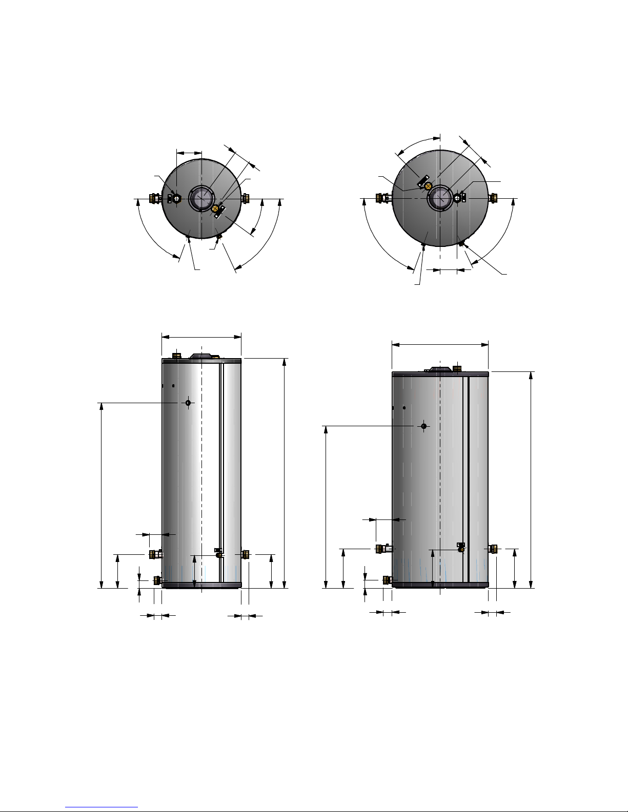
DIMENSIONS
3.1 Water heaters CONSUL+35
TWIN PIPE CONCENTRIC
Connections
Consul+35
twin pipe concentric
flue gas
Ø80
Ø 80
air inlet
Ø80
Ø125
cold water inlet
R 1½” (swivel)
hot water outlet
R 1½” (swivel)
gas R ¾” (male)
condensate
flexible hose Ø25/21 x 750 mm.
E93.0901EN.A Manual Consul+
14
3.2 Water heaters CONSUL+55
TWIN PIPE CONCENTRIC
Connections
Consul+35
twin pipe concentric
flue gas
Ø80
Ø 80
air inlet Ø80 Ø125
cold water inlet
R 1½” (swivel)
hot water outlet
R 1½” (swivel)
gas R ¾” (male)
condensate
flexible hose Ø25/21 x 750 mm.
E93.0901EN.A Manual Consul+
15
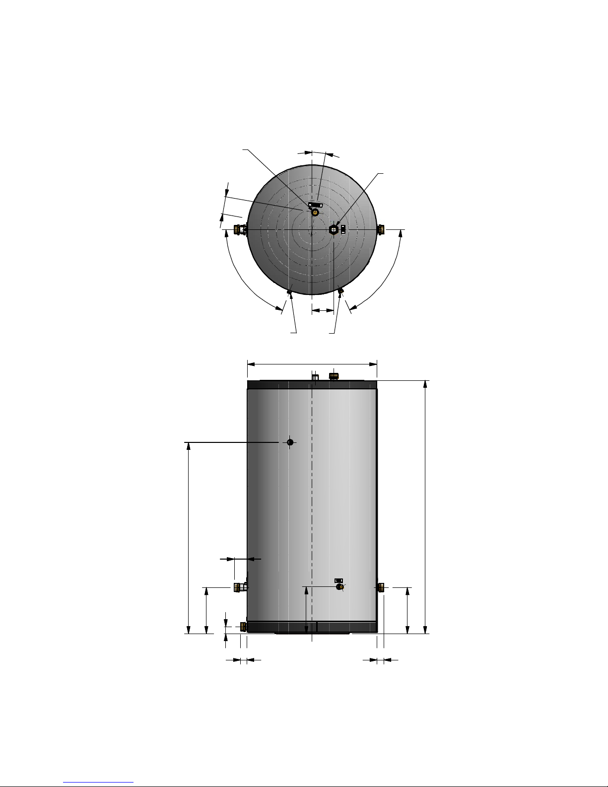
3.3 Tank EWD150 – EWD230 - EWD300 - EWD450 - EWD750
For the connections, marked A-H see § 9.3.2 on page 45-46
EWD150 EWD230
A
B
C
D
E
F
H
A
B
C
D
E
H
F
E93.0901EN.A Manual Consul+
16
EWD300 EWD450
1750
604
60
257
257
56
92
56
36°
70°
65°
734
C
A
B
D
F
H
E
190
128
70°
65°
45°
128
128
C
A
B
63
63
121
60
297
2971646
D
E
F
H
292
244
1412
1232
E93.0901EN.A Manual Consul+
17
EWD750
950
70°
65°
158
10°
128
47
92
47
338
1859
50
338
C
A
B
F
H
D
E
343
1403

E93.0901EN.A Manual Consul+
18
ACCESSORIES AND UNPACKING
4.1 Unpacking
The CONSUL+ water heater will be supplied with the following documents and accessories:
•One “Installation User and Mounting” manual
•One suspension bracket with locking plate and bolts.
•Attached to the front of the gas valve:
-Two spare fuses
-Three spare nuts for mounting the burner plate.
-A gas conversion sticker
•Temperature sensor with connector, Siphon drain hose and a dirt catcher siphon
•Double Nipple (2 pieces) with gaskets and support nipples to be used for the flow and return pipe.
•Pump Grundfos UPXML GEO 25-125-N-180
After delivery, immediately check the water heater package to see if it is complete and without any defects.
Report any imperfections immediately to your supplier.
4.2 Accessories
Depending on the selected way of controlling thesystem, the following items can be supplied with the water heater.
Ask your supplier for the specifications.
Item
Part Nº.
External DHW-Tank threaded temperature sensor 10kOhm@25°C (supplied with the
water heater), to be mounted in the screw hole on the tank outlet to the water heater E04.016.677
External DHW-Tank pipe temperature sensor 10kOhm@25°C for tank types without
screw hole in the outlet to the water heater E04.016.304
Warm water thermostat RCH S04.016.658
Hot water tank, stainless steel, EWD150 E66.000.010
Hot water tank, stainless steel, EWD230 E66.000.011
Hot water tank, stainless steel, EWD300 E66.000.203
Hot water tank, stainless steel, EWD450 E66.000.204
Hot water tank, stainless steel, EWD750 E66.000.205
Baseplate EWD150 - EWD450 tanks E01.000.412
Baseplate EWD750 tank E01.000.411
Pump Grundfos UPXML GEO 25-125-N-180 E04.016.705
Software and interface cable to program the water heater with a computer/laptop S04.016.586

E93.0901EN.A Manual Consul+
19
4.3 Flue gas and air supply parts
Twin pipe Concentric pipe
Twin pipe air and flue diameters:
Ø80
Conversion kit conc. to twin pipe
E61.001.188
Flue gas pipe SS L=1000mm
E04.018.055
Flue gas pipe SS L=500mm
E04.018.054
Flue gas pipe SS L=250mm
E04.018.053
Flue gas pipe PP L=1000mm
410085502
Flue gas pipe PP L=500mm 410085501
Flue gas pipe PP L=250mm
410085500
Adjustable pipe PP
410085027
All-purpose lead tile roof terminal
E04.018.031
Concentric roof terminal SS.
E04.018.015
Tile roof terminal
E04.018.032
Single pipe roof terminal PP
410086883
Condensate drain stainless steel
E04.018.058
Condensate drain PP
410085048
Wall pipe clamps
E04.018.083
Roof deck pipe clamps
(included in roof
term.)
Seal ring rubber
S07.004.023
Bend stainless steel 43-45°
E04.018.057
Bend stainless steel 87-90°
E04.018.056
Bend PP 43-45°
410085042
Bend PP 87-90°
410085041
Concentric wall terminal
E04.018.019
Air supply wall terminal 410082856
Manifold Air-Flue gas
(Twin-Conc)
E04.010.161
Concentric pipe diameters air and flue:
Ø80/125
Conversion kit twin pipe to concentric
E61.001.189
Flue gas pipe SS L=1000mm
E04.018.016
Flue gas pipe SS L=500mm
E04.018.067
Flue gas pipe SS L=250mm
E04.018.066
Flue gas pipe PP L=1000mm
E04.018.020
Flue gas pipe PP L=500mm
E04.018.025
Flue gas pipe PP L=250mm
E04.018.024
Adjustable pipe PP
410084457
All-purpose lead tile roof terminal
E04.018.031
Concentric roof terminal SS
E04.018.015
Roof pipe flashing
E04.018.032
Concentric roof terminal PP
E04.018.018
Air seal ring concentric roof terminal
08 1078 00
Concentric condensate drain SS
E04.018.069
Concentric condensate drain PP
E04.018.028
Wall pipe clamps
E04.018.085
Roof deck pipe clamps
E04.018.030
Seal ring gummi – Flue gas pipe
S07.004.023
Seal ring gummi – Air pipe
E07.004.024
Conc. bend SS 43-45°
E07.004.027
Conc. bend SS 87-90°
E04.018.017
Conc. bend PP 43-45°
E04.018.027
Conc. bend PP 87-90°
E04.018.021
Concentric wall terminal stainless steel
E04.018.019

E93.0901EN.A Manual Consul+
20
INSTALLATION OF THE CONSUL+
5.1 General notes
At every side of the water heater at least 50 mm of clearance should be applied to walls or wall units, 350 mm
above the top side of the water heater and 250 mm from the bottom of the water heater.
The installation area/room must have the following provisions:
•230 V - 50 Hz power source socket with earth connection.
•Open connection to the sewer system for draining condensing water
•Gas connection.
Note:
The wall used for mounting the water heater must be able to hold the weight of the water heater. If this is not the
case it is recommended to mount the water heater on a (cascade) frame.
Other considerations related to the water heater location:
•The ventilation of the plant room must meet all applicable standards and regulations, regardless of the
selected supply of fresh air to the water heater location.
•Both the air supply and the flue gas tubes must be connected to the outside wall and/or the outside roof.
•The installation area must be dry and frost-free.
•The water heater has a built-in fan that will generate noise, depending on the total heat demand. The water
heater location should minimize any disturbance this might cause. Preferably it is suggested to mount the
water heater on a brick wall.
•There must be sufficient lighting available in the plant room to work safely on the water heater.
•Remind the positioning of electrical components in relation to the temperature sensitivity.
•Make sure there is an open connection with the sewer to drain the condensate. This connection should be
lower than the condensate drain level of the water heater.
The water heater must be positioned and installed by a certified installer in accordance with all applicable stand-
ards and regulations. Commissioning of the water heater must be done by a skilled service/commissioning engi-
neer, trained for this type of water heater.
Open connection to the sewer.
This manual suits for next models
1
Table of contents
Popular Water Heater manuals by other brands

Drazice
Drazice OKC 250 NTR/HP Operating and installation instruction manual

Idrogas
Idrogas Celsior Series Instructions for use and maintenance

clage
clage ISX quick start guide

Airxcel
Airxcel SW5EA Operating, installation and service manual

MEGAFLO
MEGAFLO DD Product guide

Bradford White
Bradford White ECO-DEFENDER U130T*FRN Service manual

REXENER
REXENER PR-200 user manual

DAXOM
DAXOM UKDAX-11ST Installation and operating manual

Kenmore
Kenmore 153.321344 Use & care guide

Helios
Helios AIR1 Series Installation and operating instructions

Lochinvar
Lochinvar POWER DIRECT VENTED GAS MODELS instruction manual

Fabdec
Fabdec EXCELSIOR installation manual


