Ecodyne Water Systems IDP30S User manual
7371046 (Rev. A 6/5/18)
Designed, Engineered &
Assembled in the U.S.A.
Manufactured by
Ecodyne Water Systems
1890 Woodlane Drive
Woodbury, MN 55125
OWNER’S MANUA
How to install, operate
and maintain your
Models
IDP30S Water Softener
IDP40S Water Softener
IDP40CC*Chloramine
& Chlorine Water Conditioner
IDP50CC*Chloramine
& Chlorine Water Conditioner
Models IDP30S & IDP40S tested and certified by
NSF International against NSF/ANSI Standard 44
for hardness reduction and efficiency and the
reduction of barium and radium 226/228,
and certified to NSF/ANSI Standard 372.
Models IDP30S & IDP40S tested and certified by
the Water Quality Association against CSA 483.1.
ÙModels IDP40CC & IDP50CC have not been
tested or certified by NSF International or the
Water Quality Association.

2
SAFETY GUIDES
Follow the installation instructions carefully. Failure to
install the water filtration system properly voids the
warranty.
efore you begin installation, read this entire manual.
Then, obtain all the materials and tools you will need to
make the installation.
Check local plumbing and electrical codes. The
installation must conform to them.
Use only lead-free solder and flux for all sweat-solder
connections, as required by state and federal codes.
Use care when handling the water filtration system. Do
not turn upside down, drop, or set on sharp protrusions.
Do not locate the water filtration system where freezing
temperatures occur. Do not attempt to treat water over
120°F. Freezing, or hot water damage voids the
warranty.
Avoid installing in direct sunlight. Excessive sun heat
may cause distortion or other damage to non-metallic
parts.
The water filtration system requires a minimum water
pressure of 30 psi at the inlet. Maximum allowable
inlet water pressure is 125 psi. If daytime pressure is
over 80 psi, nighttime pressure may exceed the maxi-
mum. Use a pressure reducing valve if necessary
(Adding a pressure reducing valve may reduce the flow).
The water filtration system works on 24V DC electrical
power, supplied by a direct plug-in power supply
(included). e sure to use the included power supply,
and plug it into a nominal 120V, 60 Hz household outlet
that is in a dry location only, grounded and properly
protected by an overcurrent device such as circuit
breaker or fuse.
This system is not intended to be used for treating water
that is microbiologically unsafe or of unknown quality
without adequate disinfection before or after the system.
European Directive 2002/96/EC requires all
electrical and electronic equipment to be dis-
posed of according to Waste Electrical and
Electronic Equipment (WEEE) requirements.
This directive or similar laws are in place
nationally and can vary from region to region.
Please refer to your state and local laws for
proper disposal of the equipment.
TAB E OF CONTENTS Page
Specifications . . . . . . . . . . . . . . . . . . . . . . . . . . . . . . . 3
Performance Claims & Dimensions . . . . . . . . . . . . . . 4
efore Starting Installation . . . . . . . . . . . . . . . . . . . . 5
Typical Installation Illustrations . . . . . . . . . . . . . . . . . 6
Installation . . . . . . . . . . . . . . . . . . . . . . . . . . . . . . 7-10
Sanitizing Procedure . . . . . . . . . . . . . . . . . . . . . . . . 10
Setup Procedure . . . . . . . . . . . . . . . . . . . . . . . . . . . 11
Programming the Water Softener . . . . . . . . . . . . 12-25
Wiring Schematic . . . . . . . . . . . . . . . . . . . . . . . . . . . 24
Adding Salt . . . . . . . . . . . . . . . . . . . . . . . . . . . . . . . 26
Routine Maintenance . . . . . . . . . . . . . . . . . . . . . 26-27
Service Information . . . . . . . . . . . . . . . . . . . . . . 23-24
Troubleshooting . . . . . . . . . . . . . . . . . . . . . . . . . 28-31
Repair Parts . . . . . . . . . . . . . . . . . . . . . . . . . . . . 32-37
Warranty . . . . . . . . . . . . . . . . . . . . . . . . . . . . . . . . . 38
Table of Contents, Unpac ing & Safety Guides
UNPACKING
Models IDP30S, IDP40S and IDP40CC are shipped
from the factory in one carton. The carton also includes
a bag of small parts needed to assemble and install the
unit.
Model IDP50CC is shipped from the factory in two car-
tons. One contains the resin tank/controller assembly,
plus a bag of small parts needed to assemble and
install the unit. The other carton contains the assem-
bled brine tank.
Thoroughly check the water softener for possible ship-
ping damage and parts loss. Also inspect and note any
damage to the shipping carton.
Remove and discard (or recycle) all packing materials.
To avoid loss of small parts, we suggest you keep the
small parts in the parts bag until you are ready to use
them.

3
SPECIFICATIONS
Model IDP30S IDP40S IDP40CC*IDP50CC*
Model Code ID30S ID40S ID40C ID50C
Rated Softening Capacity
(grains @ lb. salt dose)
12,000 @ 2.4
25,600 @ 7.5
30,600 @ 12.6
11,800 @ 2.4
31,600 @ 9.0
40,000 @ 15.5
11,800 @ 2.4
31,600 @ 9.0
40,000 @ 15.5
16,600 @ 3.3
44,300 @ 12.3
56,300 @ 21.3
Rated Efficiency
(grains / lb. @ minimum salt dose) 5,090 @ 2.4 4,950 @ 2.4 4,980 @ 2.4 5,090 @ 3.3
Water Used During Regeneration @
Minimum Salt Dose
2.5 gal. /
1,000 grains
3.1 gal. /
1,000 grains
4.1 gal. /
1,000 grains
4.5 gal. /
1,000 grains
Amount of High Capacity Resin 0.79 cu. ft. 1.13 cu. ft. 1.13 cu. ft. 1.56 cu. ft.
Amount of Catalytic Carbon ––0.40 cu. ft. 0.57 cu. ft.
Amount of Gravel –––12 lbs.
Service Flow Rate 7.2 gpm 8.0 gpm 4.0 gpm 5.0 gpm
Pressure Drop at Rated Service Flow 15.0 psig 8.5 psig 10.0 psig 10.0 psig
Intermittent Flow @ 15 psi p7.2 gpm 11.7 gpm 15.0 gpm 15.0 gpm
Intermittent Flow @ 30 psi p11.0 gpm 18.1 gpm 21.0 gpm 21.0 gpm
Water Supply Maximum Hardness 50 gpg 65 gpg 65 gpg 85 gpg
Water Supply Maximum
Clear Water Iron ¢6 ppm 8 ppm 8 ppm 10 ppm
Min. - Max. Water Supply Pressure u20 - 125 psi
Min. - Max. Water Supply Temperature 40 - 120 °F
Minimum Water Supply Flow Rate 3 gpm
Max Drain Flow Rate 2.0 gpm
pIntermittent flow rate does not represent the maximum service flow rate used for determining the unit’s rated capacity
and efficiency. Continuous operation at flow rates greater than the service flow rate may affect capacity and efficiency
performance.
¢Capacity to remove clear water iron is substantiated by independent laboratory test data. State of Wisconsin requires
additional treatment if water supply contains greater than 5 ppm clear water iron.
uCanada working pressure limits: 1.4 - 7.0 kg/cm².
ÙModels IDP40CC & IDP50CC have not been tested or certified by NSF International or the Water Quality Association.
These units conform to NSF/ANSI 44 for the specific performance claims as verified and substantiated by test data.
These models are efficiency rated. The efficiency rating is valid only at the minimum salt dose and the service flow
rate. The softeners have a demand initiated regeneration (D.I.R) feature that complies with specific performance
specifications intended to minimize the amount of regenerant brine and water used in their operation.
These softeners have a rated softener efficiency of not less than 3,350 grains of total hardness exchange per pound
of salt (based on sodium chloride) and shall not deliver more salt than their listed rating or be operated at a sus-
tained maximum service flow rate greater than their listed rating. These softeners have been proven to deliver soft
water for at least ten continuous minutes at the rated service flow rate. The rated salt efficiency is measured by lab-
oratory tests described in NSF/ANSI Standard 44. These tests represent the maximum possible efficiency that the
system can achieve. Operational efficiency is the actual efficiency after the system has been installed. It is typically
less than the rated efficiency, due to individual application factors including water hardness, water usage, and other
contaminants that reduce a softener's capacity.
While testing was performed under standard laboratory conditions, actual performance of the system may vary
based on local water conditions.
Specifications
4
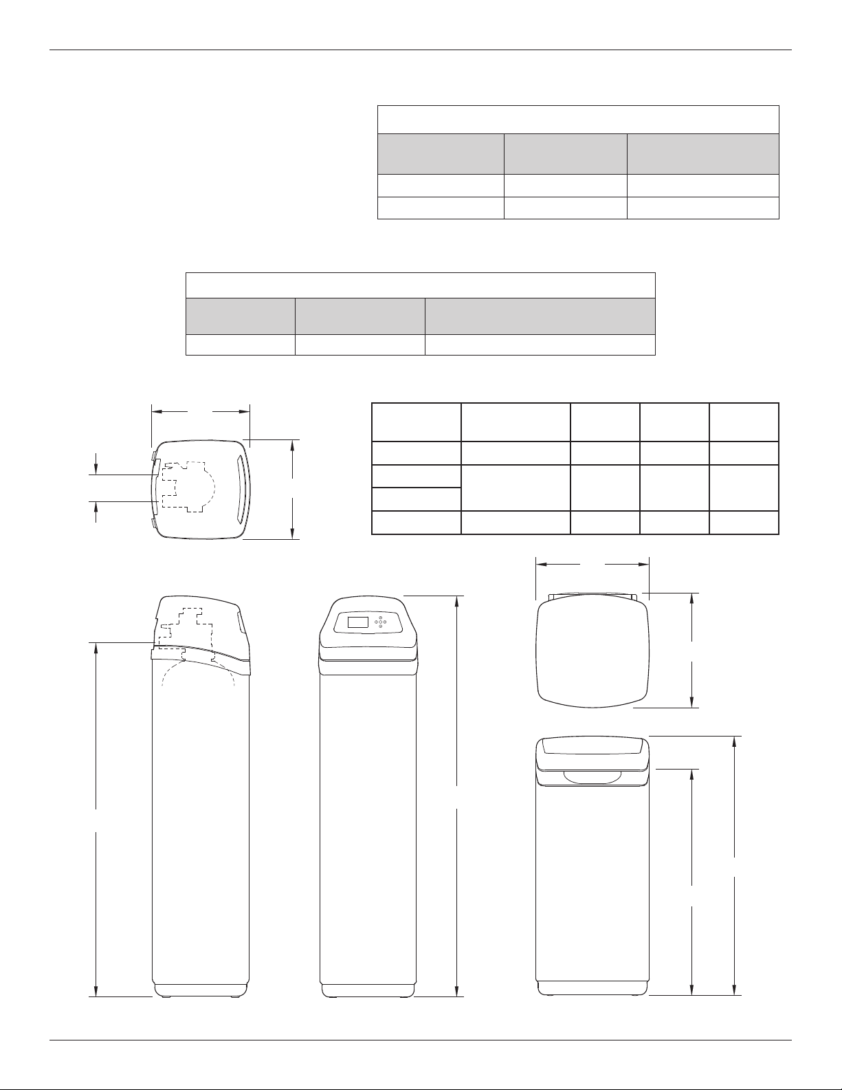
FRONT VIEWSIDE VIEW
IN - OUT
TOP VIEW
14"
14"
IN
OUT
A
16-1/4"
16"
36-9/16"
32"
BRINE TANK
B
C
14”
FIG. 1
SIDE VIEW FRONT VIEW
TOP VIEW
IN
OUT
IN - OUT
A
14”
Model Nominal Resin
Tank Size
Dimension
A
Dimension
B
Dimension
C
IDP30S 8” dia. x 40” 48-3/4” 42“ 3-3/8“
IDP40S 10” dia. x 47” 56-3/4“ 50” 3-3/4“
IDP40CC
IDP50CC 12” dia. x 54” 62-1/2” 55-3/4” 3-3/4“
C
B
16”
16-1/4”
32”
36-9/16”
RINE TANK
PERFORMANCE C AIMS
Contaminant Influent
Challenge evel
Maximum Allowable
Product Water evel
arium 10 ±10% mg/L 2.0 mg/L
Radium 226/228 25 pCi/L 5 pCi/L
Test parameters include: pH = 7.5 ±0.5
flow rate = 7.5 gpm
dynamic pressure = 35 ±5 psig
MODE S IDP40CC & IDP50CC PERFORMANCE C AIM
Substance Influent
Challenge evel Reduction Requirement
Chloramines 3 mg/L >70% @ 10 gpm for 34,000 gal.*
*From manufacturer’s test data.
Models IDP40CC & IDP50CC have not been tested or certified by NSF International or the Water Quality Association.
Performance Claims & Dimensions

5
WHERE TO INSTA THE SOFTENER
= To soften all water in the home, install the water
softener close to the water supply inlet, upstream
of all other plumbing connections, except outside
water pipes. Outside faucets should remain on
hard water to conserve salt and softening capacity.
= Place the softener near a floor drain, or other
acceptable drain point (laundry tub, sump, stand-
pipe, etc.) to carry away regeneration discharge
water.
= Connect the softener to the main water supply
pipe UPSTREAM OF the water heater. DO NOT
RUN HOT WATER THROUGH THE SOFTENER.
The temperature of water passing through the sof-
tener must be less than 120°F.
= Do not install the softener in a place where it could
freeze. Damage caused by freezing is not cov-
ered by the warranty.
= Put the softener in a place water damage is least
likely to occur if a leak develops. The manufactur-
er will not repair or pay for water damage.
= A 120V, 60 Hz electrical outlet, to plug the included
power supply into, is needed near the softener.
e sure the electrical outlet and power supply are
in an inside location, to protect from wet weather.
= If installing in an outside location, you must take
the steps necessary to assure the softener, instal-
lation plumbing, wiring, etc., are as well protected
from the elements, contamination, vandalism, etc.,
as when installed indoors.
= Keep the softener out of direct sunlight. The sun's
heat may soften and distort plastic parts.
TOO S, PIPE & FITTINGS,
OTHER MATERIA S YOU WI NEED
= ALWAYS install a single bypass valve, or a 3-valve
bypass system. ypass valves let you turn off water
to the softener for repairs if needed, but still have
water available to the house pipes.
= Plastic inlet and outlet fittings are included with the
softener, which allow water flow equivalent to 1 inch
nominal pipe. To maintain maximum valve flow, 1”
pipes to and from the softener fittings are recommend -
ed. Do not reduce the pipes to less than 3/4” size.
= Use copper, brass or PEX plastic pipe and fittings.
= Drain hose, 1/2” inside diameter minimum, is needed
for the valve drain.
= If a rigid valve drain is needed, to comply with
plumbing codes, you can buy the parts needed to
connect a 1/2” minimum copper tubing drain.
NOTE: The Commonwealth of Massachusetts plumbing
code 248-CMR shall be adhered to. A licensed plumber
shall be used for this installation.
THE PROPER ORDER TO INSTA WATER TREATMENT EQUIPMENT
FIG. 3
Pressure
Tank
City Water Supply
Well Water Supply
Well
Pump
OR
Optional
Sediment
Filter
Water
Heater
Water
Softener
Untreated Water to
Outside Faucets
Hot Water
to House
Cold Water
to House
FIG. 2
SING E BYPASS VA VE
Pull out for “Service”
(Soft water)
Push in for
“ ypass”
Before Starting Installation
This manual suits for next models
3
Table of contents
Other Ecodyne Water Systems Water Dispenser manuals

Popular Water Dispenser manuals by other brands

IBC Water
IBC Water AST0715MP-960 Installation & operating instructions

Lancaster Water Treatment
Lancaster Water Treatment X FACTOR LX15 Series Installation, operating and service manual

Elkay
Elkay EMABF8 Series Installation & use manual

Oasis
Oasis Osmosis Home installation manual

Monarch Water
Monarch Water ULTIMATE MINI AQUA HE install guide

Haier
Haier HLM-109B instruction manual


