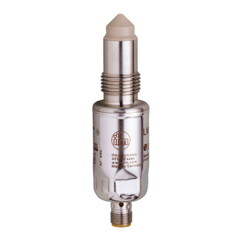
Ecolab Sensopart FT 55-RLAP User manual

PARAMETRY TECHNICZNE| TECHNICAL DATA | DONNÉES TECHNIQUES | DATOS TÉCNICOS (TYP.)
FT 55 -RLAP-...-PNSI-xx -RLAP-...-PNSU-xx
Polaryzacja wyjścia Q Switching output Q FSortie de commutation Q ESalida de conmutación Q detekcja automatyczna/Auto-Detect
Zakres pomiarowy 1) Measurement range 1) Étendue de mesure 1) Campo de medida 1) 0,1 ... 5 m
Rodzaj światła Used light Type de lumière Tipo de luz Laser, klasy 1 (EN60825-1)
Napięcie zasilające +UB2) Operating voltage +UB2) Tension d‘alimentation +UB2) Tensión de servicio +UB2) 18 … 30 V DC
Pobór prądu bez
obciążenia I0
No-load supply current I0Courant hors charge I0Corriente en vacío I0≤ 60 mA
Obciążenie wyjścia Ie Q Output current Ie Q Courant de sortie Ie Q Corriente de salida Ie Q ≤ 100 mA
Sygnał analogowy QAAnalogue output QASortie analogique QASalida analógica QA 4 ... 20 mA 0 ... 10 V
Wejście programowania
IN 3) Control input IN 3) Entrée de contrôle IN 3) Entrada de control IN 3)
+UB= Teach-in/programowanie
-UB=
brak połączenia = detekcja
Ustawienia fabryczne Factory setting Conguration d‘origine Ajuste de fábrica QA: 0,3 ... 3 m
Q: 0,3 ... 3 m
1) Materiał odniesienia, biały
90% odbicia
1) Reference material white,
90% reectance
1) F Matériau de référence
blanc, 90% réexion
1) E Material de referencia blanco,
90% de reexión
D= blokada
przycisku
= button locked F = bouton verrouillée E = tecla bloqueado
2) tętnienia max. 10% , UB,
~50Hz/100Hz
2) max. residual ripple 10%,
within UB, approx. 50Hz/100Hz
2) Ondulation résiduelle maxi
10 % à l‘intérieur de UB, env.
50Hz/100Hz
2) máx. 10% de ondulación
residual, dentro de UB, aprox.
50Hz/100Hz
3) patrz ilustracja K 3) see illustration K; back 3) voir illustration K; verso 3) véase el gráco K; reverso
FT 55-RLAP
Czujnik pomiaru odległości
Distance sensor
Capteur de distance
Sensor de distancia
068-14524 18.03.2014-00
www.sensopart.com
Uważnie przeczytaj instrukcję przed podłączeniem czujnika.
Połączenia, montaż, programowanie tylko przez wykwa-
likowany personel.
Zgodnie z dyrektywą UE nie stosować jako element
układu bezpieczeństwa dla personelu.
Nie stosować na zewnątrz.
FT 55-RLAP-xxx: , Klasa 1; długość fali: 655nm;
Częstotliwość: 45kHz; czas trwania impulsu: 8ns; moc
impulsu: < 930mW (EN60825-1).
Zgodnie z 21 CFR 1040.10 i 1040.11 z wyjątkiem od-
stępstw dotyczących mocy lasera w uwadze nr 50 z
24.06.2007.
Czujnik jest przeznaczony do bezkontaktowego pomiaru
odległości.
Zalecany montaż przy użyciu odpowiednich akcesoriów
(szczegóły, patrz www.sensopart.com).
Połączyć konektor z gniazdem kabla i mocno skręć.
Podłączyć żyły kabla zgodnie ze schematem połączeń.
(patrz rys. B).
Wybór automatycznej detekcji/ PNP/NPN (patrz ilustracja I).
Dołączyć zasilanie → zaświeci się dioda LED zielona.
Przełączanie N.O. ↔ N.C. (patrz ilustracja J).
N.O. = funkcja zwierna; N.C. = funkcja rozwierna.
REGULACJA (PATRZ ILUSTRACJA C)
Skierować czujnik w kierunku wykrywanego obiektu.
Obserwować preferowany kierunek wiązki nadawczej czujnika.
SAFETY INSTRUCTIONS
Read operating instructions before start-up.
Connection, assembly, setting and start-up only by
trained personnel.
No safety component according to EU machinery directi-
ves (not suited for the protection of personnel).
Not for outdoor use.
FT 55-RLAP-xxx: , class 1; wavelength: 655nm;
frequency: 45kHz; pulse duration: 8ns; limit value pulse:
< 930mW (EN60825-1).
Complies with 21 CFR 1040.10 and 1040.11 except for
deviations pursuant to laser Notice No. 50 dated June
24, 2007.
INTENDED USE
Sensor is used for the optical non-contact detection of
objects.
ASSEMBLY
Fix sensor on suitable mounting component
(see www.sensopart.com).
CONNECTION
Insert plug tension-free and screw it tightly.
Connect cable according to the connection diagram (see
illustration B) .
For Auto-Detect / PNP/NPN (see illustration I; back).
Apply voltage → green LED lights up.
Switching N.O. ↔ N.C. (see illustration J; back).
N.O. = normally open; N.C. = normally closed.
ADJUSTMENT (SEE ILLUSTRATION C)
Align sensor to the target object.
Observe the preferential direction of proximity switches.
FINSTRUCTIONS DE SÉCURITÉ
Lire les instructions de service avant mise en service.
Raccordement, assemblage, réglage et mise en service
ne doivent être effectués que par du personnel qualié.
Il ne s‘agit pas de pièces de sécurité selon les directives
européennes en vigueur concernant les machines (inap-
propriées à la protection de personnes).
Nepas utiliser à l‘extérieur.
FT 55-RLAP-xxx: , classe 1; longueur d‘onde:
655nm; fréquence: 45kHz; largeur d‘impulsion: 8ns;
valeur limite impulsion: < 930mW (EN60825-1).
Correspond à 21 CFR 1040.10 et 1040.11 à l‘exception
des différences conformément à la notice du laser n° 50
du 24 juin 2007.
UTILISATION CONFORME
Le capteur est utilisé pour la détection optique des objets
sans contact.
MONTAGE
Monter le capteur sur une équerre de xation appropriée
(voir www.sensopart.com).
RACCORDEMENT
Insérer le connecteur hors tension et visser.
Connecter le câble selon le schéma de raccordement
(voir illustration B).
Pour Auto-Detect / PNP/NPN (voir illustration I; verso).
Mettre sous tension → LED verte est allumée.
Inversion N.O. ↔ N.C. (voir illustration J; verso).
N.O. = ouverture; N.C. = fermeture.
AJUSTEMENT (VOIR ILLUSTRATION C)
Aligner le capteur sur l‘objet à détecter.
Observer la direction préférencielle des capteurs optiques
de proximité.
EINDICACIONES DE SEGURIDAD
Antes de la puesta en marcha, lea las instrucciones de servicio.
La conexión, el montaje, el ajuste y la puesta en marcha
deben correr a cargo únicamente de personal especializado.
No es una pieza de seguridad según la directiva de
máquinas de la UE (no es adecuada para la protección
de personas).
No utilice en el exterior.
FT 55-RLAP-xxx: , clase 1; longitud de onda:
655nm; frecuencia: 45kHz; amplitud de pulso: 8ns; valor
límite de pulso: < 930mW (EN60825-1).
Cumple las normas 21 CFR 1040.10 y 1040.11, a excep-
ción de las desviaciones según la nota sobre láser n° 50
del 24 de junio de 2007.
USO DEBIDO
El sensor se usa para la detección óptica sin contacto
de objetos.
MONTAJE
Fije el sensor a un soporte adecuado (para el soporte
véase www.sensopart.com).
CONEXIÓN
Conecte y atornille el conector cuando no haya tensión.
Conecte el cable. Aplique el esquema de conexión
(véase el gráco B).
Para Auto-Detect / PNP/NPN (véase el gráco I
; reverso
).
Aplique la tensión → el LED verde se enciende.
Conmutación N.O. ↔ N.C. (véase el gráco
J
; reverso).
N.O. = contacto de cierre; N.C. = contacto de apertura.
AJUSTE (VÉASE EL GRÁFICO C)
Oriente el sensor hacia el objeto que deba detectarse.
Tenga en cuenta la dirección preferente en los interruptores.
F E
1LED żółta
1)
Yellow LED
1) LED jaune
1) LED amarillo 1)
2LED żółta 2)
LED zielona
3)
Yellow LED
2)
Green LED
3)
LED jaune 2)
LED verte 3)
LED amarillo 2)
LED verde 3)
3Przyciski 4)
QA / Q
Buttons 4)
QA / Q
Boutons 4)
QA / Q
Teclas 4)
QA / Q
4Oś nadaj-
nika
Emitter axis Axe
d‘émetteur
Eje de
emisión
5Oś odbior-
nika
Receiver
axis
Axe de
récepteur
Eje de
recepción
1) Sygnalizacja wyjścia binarnego Q | switching output indicator Q
afcheur sortie de commutation Q | indicación de salida de conexión Q
2) Sygnalizacja wyjścia analogowego QA | analogue output indicator QA
afcheur sortie analogique QA | indicación de la salida analógica QA
3) Sygnalizacja zasilania | operating voltage indicator
afcheur tension de service | indicación de tensión de servicio
4) QA: programowanie wyj. analog / Q: progr. wyj. binarnego
QA: analogue output / Q: switching output
QA: sortie analogique / Q: afcheur sortie de commutation
QA: salida analógica / Q:indicación de salida de conexión
FT 55-RLAP
A8.6
B28.4
5-pin
+
-
-UB3 BU
Q 4 BK
IN 5 GY
-
+UB
QA
1
2
BN
WH
+Auto-Detect
12
Mx1
23
50
13.95
16
44
46
4.3
50.08
5.8
13
2
4
5
A
B
110 mm
1 m 5 m
70 mm
110 mm
1 m 5 m
70 mm
1 3
2
Q
QA
B. A. ESQUEMA DE DIMENSIONES
C.
Regulacja kierunku wiązki laserowej za pomocą opcjonalnego uchwytu montażowego MA F55 / 579-50007
Adjustment of light spot postion with optional mounting angle MA F55 / 579-50007
Réglage de la position du spot lumineux par l'équerre de montage MA F55 / 579-50007 qui est disponible en option
Ajuste de la posición del punto luminoso mediante el ángulo de montaje opcional MA F55 / 579-50007
Unikać dodatkowych jasnych obiektów w zakreślonym obszarze.
Prevention of further light spots in the hatched area
Blocage de spots lumineux supplémentaires en zone hachurée
Evitación de puntos luminosos adicionales en el área sombreada

Automatyczna
Czujnik posiada dwa niezależnie programowalne wyjścia
sygnału analogowego i cyfrowego.
Dwa punkty procesu programowa-
nia określają początek i koniec zakresu pomiarowego i
zakres sygnału pomiarowego (patrz ilustracja F).
Programowanie, punkt 1 = 4 mA / = 0.09 V.
Programowanie, punkt 2 = 20 mA / = 10 V.
Dwa punkty procesu uczenia określają
początek i koniec zakresu pomiarowego okna (patrz
ilustracja G)
: Zasadę programowania
pokazują charakterystyki sygnału analogowego QAoraz
cyfrowego typu okno Q. (patrz ilustracja H).
Patrz ilustracja E
Czujniki produkcji SENSOPART nie wymagają specjal-
nej konserwacji. Jedynie zaleca się cykliczne czyszcze-
nie powierzchni optycznej czujnika oraz sprawdzanie
mocowania mechnicznego i podłączenia konektora.
SETTING
The sensor has an analogue and a switching output,
which can be set independent of each other.
The two teach points identify the
beginning and end of the measuring area and scale the
analogue output (see illustration F).
Teach 1 = 4 mA / 0.09 V.
Teach 2 = 20 mA / 10 V.
The two teaching points identify
the beginning and end of the switching window (see
illustration G).
: The teach sequence and object
distance determine the characteristics of the analogue
output QA and the window width of the switching output
Q(see illustration H).
FACTORY SETTING
See illustration E
MAINTENANCE
SENSOPART sensors are maintenance-free. We recom-
mend to cyclically clean the optical surfaces and check
the screw connections and plug connections.
FRÉGLAGE
Le capteur dispose d'une sortie analogique et d'une
sortie à seuil qui peuvent être réglées indépendamment
l'une de l'autre.
: Les deux points d'apprentissage
marquent le début et la n de l'étendue de mesure et ils
mettent la sortie analogique à l'échelle (voir illustration F).
Teach 1 = 4 mA / 0,09 V.
Teach 2 = 20 mA / 10 V.
: Les deux points d'apprentissage
marquent le début et la n de la fenêtre de commutation
(voir illustration G).
: L'ordre d'apprentissage et la
distance de l'objet déterminent la ligne caractéristique de
la sortie analogique QA et la largeur de la fenêtre de la
sortie à seuil Q (voir illustration H).
CONFIGURATION D'ORIGINE
Voir illustration E
ENTRETIEN
Les capteurs SENSOPART ne demandent aucun
entretien. Nous recommandons de nettoyer les surfaces
optiques et vérier les raccordements et les xations
régulièrement.
ECONFIGURACIÓN
El sensor dispone de una salida analógica y una salida
de conmutación que pueden congurarse de manera
independiente entre sí.
(véase Gráco F): Los dos puntos de
programación identican el principio y el nal del rango
de medición y escalan la salida analógica (véase el
gráco F).
Teach 1 = 4 mA / 0,09V.
Teach 2 = 20 mA / 10 V.
Los dos puntos de programa-
ción identican el principio y el nal de la ventana de
conmutación (véase el gráco G).
: La secuencia de programaci-
ón y la distancia al objeto determinan la línea caracterí-
stica de la salida analógica QA y la anchura de ventana
de la salida de conmutación Q (véase el gráco H).
AJUSTE DE FÁBRICA
Véase el gráco E
MANTENIMIENTO
Los sensores SENSOPART no necesitan manteni-
miento. Se recomienda limpiar las supercies ópticas a
intervalos regulares y comprobar las uniones atornilla-
das y conexiones.
Änderungen vorbehalten | subject to change | sous réserve de modications | salvo modicaciónwww.sensopart.com
QAQ
K.
Zwarcie i rozwarcie połączenia
odpowiada wciśnięciu i zwolnieniu przycisku czujnika.
Closing and opening times according
to the respective information stated in the overview D..
F Temps de fermeture et
d‘ouverture selon les spécications données dans l'aperçu D..
E Tiempos de
cierre y apertura según las indicaciones respectivas en el resumen D..
aż diody LED zielona i żółta zaczną równocześnie migać aż żółte diody LED zaczną migać jednocześnie
Teach 1 = Teach 2
Teach 1 = Teach 2
Teach 1 Teach 1Teach 2 Teach 2
Teach 1 Teach 2
Measurement range
Q
High
Low
Q
High
Low
Teach 1 Teach 2
Measurement range
Q
High
Low
Q
High
Low
Measurement range
Q
High
Low
Q
High
Low
QAQA
QA
3.6 mA / 0.06 V 3.6 mA / 0.06 V3.6 mA / 0.06 V
4 mA / 0.09 V 4 mA / 0.09 V4 mA / 0.09 V
20 mA / 10 V 20 mA / 10 V
12 mA / 5 V
20 mA / 10 V
21.1 mA / 11 V 21.1 mA / 11 V21.1 mA / 11 V
Zone A
Wejście programowania IN → ilustracja K. Wejście programowania IN → ilustracja K.
A> 3 s A> 1 s
...
aż diody LED zaczną
migać jednocześnie
aż diody LED zielona i żółta
zaczną migać na przemian
N.O.
zielona LED miga
żółta LED świeci
N.O.
zielona LED miga
żółta LED nie świeci
N.C.
ok
aż diody LED zielona i żółta
zaczną migać jednocześnie
ok
ok
...
NPN
ok
zielona dioda LED
miga
PNP
ok
żółta dioda LED miga
Funkcja Akcja krok 1 1)
Charakterystyka analogowa wciśnij QA > 3 s podłączenie IN > 3 s F.
Wyjście cyfrowe wciśnij Q > 3 s podłączenie IN > 6 s G.
Automatyczna detekcja / NPN / PNP wciśnij Q > 10 s podłączenie IN > 10 s I.
Zmiana funkcji N.O. / N.C. wciśnij Q > 13 s podłączenie IN > 13 s J.
1) Krok 2: wciśnij QA (lub Q) / podłącz IN > 1 s Utrzymuj QA-
programowanie
krok 1 = 0.09 V / 4 mA
Krok 1
Krok 2
programowanie
krok 2 = 10 V / 20 mA
zielona LED
nie świeci się
aż obie żółte diody LED zaświecą
się równocześnie 3x
* Tryb automatycznego reektora: wszystkie obiekty nieprzeźroczyste są skutecznie wykryte w stree A * Automatic reector mode: All non-transparent objects in zone A are reliably detected
* Fonctionnement obligatoire avec réecteur : Reconnaissance able de tous objets non transparents en zone A I * Funcionamiento forzado con reector: Todos los objetos no transparentes en la zona A son detectados de forma able
** Minimalna mozliwa szerokość okna ± 80 mm I Min. switching window ± 80 mm I Fenêtre de commutation ± 80 mm min. I Min. ventana de conmutación ± 80 mm
* **
zielona LED
nie świeci się
A
GY IN
+UB
BN
zielona LED
miga
E.
D. ÇU | VISIÓN GENERAL
F.
Krok 1: Obiekt w pozycji 1 Krok 2: Obiekt w pozycji 2
G.
Krok 1: Obiekt w pozycji 1 Krok 2: Obiekt w pozycji 2
H.
Krok 1
Krok 2
QA
Q
N.O.
Q
N.C.
J.
I.
G.
F.
SELS Sp. z o.o. sp. k. ul. Malawskiego 5a, 02-641Warszawa,
tel.: (022) 848 08 42, 848 52 81, fax: 848 16 48
ok
ok
ok
Other Ecolab Accessories manuals
Popular Accessories manuals by other brands

Dometic
Dometic PERFECTWALL PW3800 installation manua
nologo
nologo ZOOM-LINE90 Instructions and warnings

BEBE CONFORT
BEBE CONFORT Laika soft carrycot Instructions for use
Maretron
Maretron TMP100 Exhaust Gas Temperature Probe... user manual

Jaypro Sports
Jaypro Sports CV553B Assembly instructions and owner's manual
miniBatt
miniBatt PowerGOO user manual
