Maretron TMP100 Exhaust Gas Temperature Probe... User manual

®®
Revision 1.0 Page i
TMP100
Temperature Module
User’s Manual
Revision 1.0
Copyright © 2008 Maretron, LLP All Rights Reserved
Maretron, LLP
9014 N. 23rd Ave #10
Phoenix, AZ 85021-7850
http://www.maretron.com
Maretron Manual Part #: M002101

TMP100 User's Manual
Page ii Revision 1.0
Revision History
Revision Description
1.0 Original document

®®
Revision 1.0 Page iii
Table of Contents
1Introduction ...........................................................................................................................1
1.1Firmware Revision.................................................................................................... 1
1.2TMP100 Features..................................................................................................... 1
1.3TMP100 Accessories................................................................................................ 2
1.4Quick Install.............................................................................................................. 2
2Installation .............................................................................................................................2
2.1Unpacking the Box ................................................................................................... 2
2.2Choosing a Mounting Location ................................................................................. 2
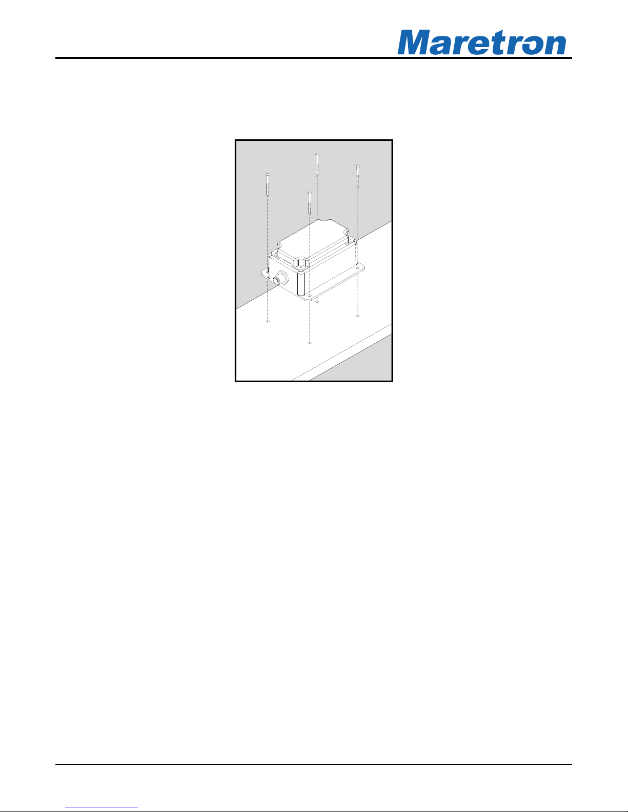
2.3Mounting the TMP100 .............................................................................................. 3
2.4Connecting the TMP100........................................................................................... 3
2.4.1NMEA 2000®Connection............................................................................... 3
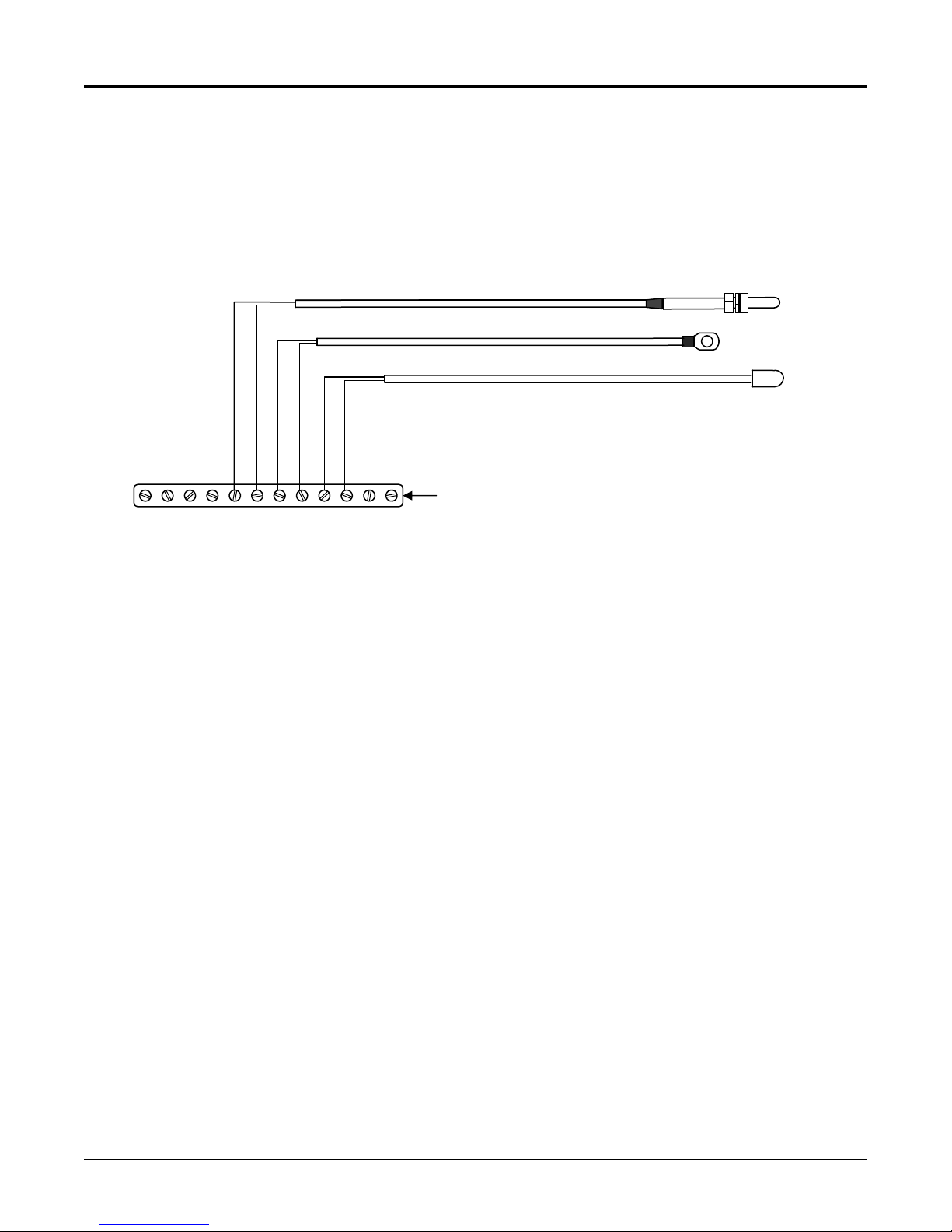
2.4.2Temperature Probe Connections................................................................... 4
2.4.2.1Exhaust Gas Temperature (EGT) Probe.......................................... 5
2.4.2.2Thermistor Type Probes (Ring/Under Bolt, Ambient Air, or
Immersion Probe) .......................................................................................... 5
2.4.3Checking Connections................................................................................... 6
2.5Configuring the TMP100........................................................................................... 6
2.5.1Channel #0 - #1 Source................................................................................. 6
2.5.2Channel #2 - #5 Source................................................................................. 7
2.5.3Channel #0 - #5 Instance............................................................................... 7
2.5.4Channel #0 - #5 Label ................................................................................... 7
2.5.5Advanced Configuration…............................................................................. 7
2.5.5.1NMEA 2000®PGN Enable/Disable .................................................. 7
2.5.5.2Restore Factory Defaults ................................................................. 7
2.5.5.3Installation Description… ................................................................. 8
3Maintenance..........................................................................................................................8
4Troubleshooting ....................................................................................................................8
5Technical Specifications........................................................................................................9
6Technical Support ...............................................................................................................10
7Installation Template ...........................................................................................................11
8Maretron (2 Year) Limited Warranty....................................................................................12
Table of Figures
Figure 1 – Mounting the TMP100 .............................................................................................. 3
Figure 2 – NMEA 2000®Connector Face Views ....................................................................... 4
Figure 3 – Exhaust Gas Temperature Probe Connection Diagram ........................................... 5
Figure 4 – Ring/Under Bolt, Ambient Air, or Immersion Temperature Probe Connection
Diagram.............................................................................................................................. 6
Figure 5 – Mounting Surface Template ................................................................................... 11

TMP100 User's Manual
Page iv Revision 1.0
Table of Appendices
Appendix A – NMEA 2000®Interfacing.................................................................................... A1

®®
Revision 1.0 Page 1
1 Introduction
Congratulations on your purchase of the Maretron Temperature Module. Maretron has
designed and built your TMP100 to the highest standards for years of dependable and
accurate service.
Maretron's TMP100 measures the temperature for up to 6 temperature probes and reports the
information over an NMEA 2000®network. The TMP100 supports up to 4 thermistor probes
and 2 high temperature thermocouple probes. Optional thermistor probes (-20°C to 80°C or -
4°F to 176°F) cover a wide range of applications including cabin air temperature, engine room
air temperature, refrigerator/freezer temperature, under bolt temperature (inverters, charges,
pumps, motors, etc.), tank temperatures (live well bait, hot water, etc.), and air duct
temperatures. The optional thermocouple probes (0°C to 900°C or 32° to 1652°F) are used to
measure Exhaust Gas Temperature (EGT) as part of a comprehensive fuel management
system.
The Maretron TMP100 is designed to operate within the harsh demands of the marine
environment. However, no piece of marine electronic equipment can function properly unless
installed, configured, and maintained in the correct manner. Please read carefully and follow
these instructions for installation, configuration, and usage of the Maretron TMP100 in order to
ensure optimal performance.
1.1 Firmware Revision
This manual corresponds to TMP100 firmware revision 1.0.3.
1.2 TMP100 Features
The Maretron TMP100 has the following features.
•NMEA 2000®Interface
•Waterproof Connectors
•Sealed Waterproof Enclosure
•Opto-Isolated from NMEA 2000®Eliminating Potential Ground Loops
•Six External Temperature Probes are Measured and Broadcast Over NMEA 2000®
Network
•Four Channels for Thermistor Probes and 2 Channels for High Temperature
Thermocouple Probes
•Wide Variety of Applications Supported with Optional Temperature Probes
- Cabin Temperature
- Engine Room Temperature
- Under Bolt Temperature (Inverters, Chargers, Pumps, etc.)
- Refrigerator/Freezer Temperature
- Tank Temperatures (Live Well Bait, Hot Water, etc.)
- Air Duct Temperature
- Exhaust Gas Temperature
- User Defined Temperature Types (#129-#144)
•Optional Temperature Probes

TMP100 User's Manual
Page 2Revision 1.0
- Ambient Air Temperature Probe (-20°C to 80°C or -4°F to 176°F)
- Ring Terminal Probe (-20°C to 80°C or -4°F to 176°F)
- Immersion Probe for Tanks or Plenums (-20°C to 80°C or -4°F to 176°F)
- Exhuast Gas Temperature Probe (0°C to 900°C or 32° to 1652°F)
1.3 TMP100 Accessories
Maretron offers the following Accessories for the TMP100:
•TR3K TMP100 Ring/Under Bolt Temperature Probe
•TP-AAP-1 TMP100 Ambient Air Temperature Probe
•TP-IP-1 TMP100 Immersion (Tanks, Plenums, etc.) Temperature Probe
•TP-EGT-1 TMP100 Exhaust Gas Temperature Probe
1.4 Quick Install
Installing the Maretron TMP100 involves the following five steps. Please refer to the individual
sections for additional details.
1. Unpack the box (Section 2.1)
2. Choose a mounting location (Section 2.2)
3. Mount the TMP100 (Section 2.3)
4. Connect the TMP100 (Section 2.4)
5. Configure the TMP100 (Section 2.5)
2 Installation
2.1 Unpacking the Box
When unpacking the box containing the Maretron TMP100, you should find the following items:
1 – TMP100 – Temperature Module
1 – Parts Bag containing 4 Stainless Steel Mounting Screws
1 – TMP100 User’s Manual
1 – Warranty Registration Card
If any of these items are missing or damaged, please contact Maretron.
2.2 Choosing a Mounting Location
Please consider the following when choosing a mounting location.
1. The TMP100 is waterproof, so it can be mounted in a damp or dry location.
2. The orientation is not important, so the TMP100 can be mounted on a horizontal deck,
vertical bulkhead, or upside down if desired.
3. The TMP100 is temperature-rated to 55°C (130°F), so it should be mounted away from
engines or engine rooms where the operating temperature exceeds the specified limit.

®®
Revision 1.0 Page 3
2.3 Mounting the TMP100
Attach the TMP100 securely to the vessel using the included stainless steel mounting screws
or other fasteners as shown in Figure 1 below.
Figure 1 – Mounting the TMP100
2.4 Connecting the TMP100
The TMP100 requires two types of electrical connections: 1) the NMEA 2000®connection
(refer to Section 2.4.1), and 2) the temperature probe connections, which are described in
Section 2.4.2.
2.4.1 NMEA 2000®Connection
The NMEA 2000®connector can be found on the side of the enclosure. The NMEA 2000®
connector is a round five pin male connector (see Figure 2). You connect the TMP100 to an
NMEA 2000®network using a Maretron NMEA 2000®cable (or compatible cable) by
connecting the female end of the cable to the TMP100 (note the key on the male connector
and keyway on the female connector). Be sure the cable is connected securely and that the
collar on the cable connector is tightened firmly. Connect the other end of the cable (male) to
the NMEA 2000®network in the same manner. The TMP100 is designed such that you can
plug or unplug it from an NMEA 2000®network while the power to the network is connected or
disconnected. Please follow recommended practices for installing NMEA 2000®network
products.

TMP100 User's Manual
Figure 2 – NMEA 2000®Connector Face Views
2.4.2 Temperature Probe Connections
The TMP100 temperature probe connections are made by connecting to the 12-pin terminal
strip on the top of the unit. First, remove the four screws at the corners of the unit detaching
the splash guard from the unit. On the bottom of the splash guard, you will find a label
detailing the wire connection to pin number assignments, which are repeated in the table
below.
Pin # Signal Name Connection
1 T0+ Exhaust Gas Temperature Probe 0 (positive terminal)
2 T0- Exhaust Gas Temperature Probe 0 (negative terminal)
3 T1+ Exhaust Gas Temperature Probe 1 (positive terminal)
4 T1- Exhaust Gas Temperature Probe 1 (negative terminal)
5 T2+ Temperature Probe 2 (positive terminal)
6 T2- Temperature Probe 2 (negative terminal)
7 T3+ Temperature Probe 3 (positive terminal)
8 T3- Temperature Probe 3 (negative terminal)
9 T4+ Temperature Probe 4 (positive terminal)
10 T4- Temperature Probe 4 (negative terminal)
11 T5+ Temperature Probe 5 (positive terminal)
12 T5- Temperature Probe 5 (negative terminal)
Before attempting to connect the TMP100 to the temperature probes, determine the type of
system you will be monitoring. The TMP100 supports the connection and monitoring of two
different system types; 1) Exhaust Gas Temperature probes (Section 2.4.2.1), or 2) thermistor
type probes (ring/under bolt probes, immersion probes, and ambient air probes; please see
Section 2.4.2.2).
Page 4Revision 1.0

®®
2.4.2.1 Exhaust Gas Temperature (EGT) Probe
The TP-EGT-1 exhaust gas temperature probe may be used to measure temperatures other
than exhaust gas temperatures; however, the TP-EGT-1 exhaust gas temperature probe is the
only TMP100 temperature probe that has sufficient range to measure exhaust gas
temperature.
NOTE: You may connect TP-EGT-1 exhaust gas temperature probes only to the terminal pairs
T0+/T0- (pins 1 and 2) or T1+/T1- (pins 3 and 4).
Please refer to Figure 3 for connecting the TMP100 to an TP-EGT-1 exhaust gas temperature
probe. Please be sure to connect the red wire from the EGT probe to the negative “-“ terminal,
and the yellow wire from the EGT probe to the positive “+” terminal. This figure shows the
connection of the exhaust gas temperature probe temperature channel 0 via the terminals
named T0+ and T0-. Connection to channel 1 is similar.
Revision 1.0 Page 5
Figure 3 – Exhaust Gas Temperature Probe Connection Diagram
2.4.2.2 Thermistor Type Probes (Ring/Under Bolt, Ambient Air, or Immersion Probe)
NOTE: You may connect TR3K ring/under bolt,TP-AAP-1 ambient air, and TP-IP-1 immersion
probes only to the terminal pairs T2+/T2- (pins 5 and 6), T3+/T3- (pins 7 and 8), T4+/T4- (pins
9 and 10), or T5+/T5- (pins 11 and 12).
EGT Probe
1 2 543 6 7 8 9 10 11 12
T0+
T1-
TMP100 Screw Terminals
Yellow
Red
T0-
T1+
T2+
T2-
T3+
T3-
T4+
T4-
T5+
T5-

TMP100 User's Manual
Please refer to Figure 4 for connecting the TMP100 to a TR3K ring/under bolt thermistor
temperature probe, TP-AAP-1 ambient air temperature probe, or TP-IP-1 immersion
temperature probe. This figure shows the connection of the TP-IP-1 immersion probe to
channel 2 via the terminals named T2+ and T2-, the TR3K ring/under bolt probe to channel 3
via the terminals named T3+ and T3-, and the TP-AAP-1 ambient air probe to channel 4 via
the terminals named T4+ and T4-. Connection to channel 5 is similar.
TP-IP-1 Immersion Probe
Page 6Revision 1.0
Figure 4 – Ring/Under Bolt, Ambient Air, or Immersion Temperature Probe Connection
Diagram
2.4.3 Checking Connections
Once the NMEA 2000® connection and temperature probe connection(s) to the TMP100 have
been completed, check to see that information is being properly transmitted by observing an
appropriate NMEA 2000®display. If you don’t see temperature indications, refer to Section 4,
“Troubleshooting”.
2.5 Configuring the TMP100
The TMP100 will transmit data over the NMEA 2000®network as it is shipped from the factory;
however, it may require configuration, depending on the types of temperature measurements
you are making. There are several configurable items within the TMP100, which are detailed in
the remainder of this section.
You configure the TMP100 using a Maretron DSM250 display or other NMEA 2000®display
unit that is capable of configuring the TMP100. Please refer to the Maretron DSM250 User’s
Manual for details.
2.5.1 Channel #0 - #1 Source
You must configure the TMP100 as to what type of temperature measurement it is
transmitting. Possible values for channels 0 and 1 include Sea Temperature, Outside
1 2 543 6 7 8 9 10 11 12
T0+
T1-
TMP100 Screw Terminals
TR3K Ring/Under
Bolt Probe
TP-AAP-1 Ambient Air Probe
T0-
T1+
T2+
T2-
T3+
T3-
T4+
T4-
T5+
T5-
Red
Black
Black
Red
Red
Black

®®
Revision 1.0 Page 7
Temperature, Inside Temperature, Engine Room Temperature, Main Cabin Temperature, Live
Well Temperature, Bait Well Temperature, Refrigeration Temperature, Heating System
Temperature, Freezer Temperature, Exhaust Gas Temperature, and User Defined
Temperature #129-#144.. You may also disable the channel by programming the “Disabled”
value into this field.
2.5.2 Channel #2 - #5 Source
You must configure the TMP100 as to what type of temperature measurement it is
transmitting. Possible values for channels 2, 3, 4, and 5 include Sea Temperature, Outside
Temperature, Inside Temperature, Engine Room Temperature, Main Cabin Temperature, Live
Well Temperature, Bait Well Temperature, Refrigeration Temperature, Heating System
Temperature, Freezer Temperature, and User Defined Temperature #129-#144. (please note
that Exhaust Gas Temperature is not available on channels 2, 3, 4, and 5). You may also
disable the channel by programming the “Disabled” value into this field.
2.5.3 Channel #0 - #5 Instance
Each temperature measurement with a given source must have a unique instance number
associated with it. This enables monitoring software and displays to distinguish different
temperature measurements from one another. For example, if a channel is programmed to
transmit a source type of Exhaust Gas Temperature and the instance for that channel is set to
a value of 0, then no other Exhaust Gas Temperature measurement on the network may use
an instance number of 0.
2.5.4 Channel #0 - #5 Label
Each channel that can be monitored by the TMP100 may be programmed with a text label that
will be displayed in monitoring software and displays that recognize device labels, such as the
Maretron N2KView Vessel Monitoring System and the Maretron DSM250 display. The label
will let you assign an easy-to-remember text label (example: “Forward Bilge Pump”) to make it
easy for you to identify the device as you are configuring the monitoring software or display, as
well as when alerts are generated.
2.5.5 Advanced Configuration…
Certain parameters do not normally need to be set in order for normal operation, but are
included in an advanced configuration section for use in special situations.
2.5.5.1 NMEA 2000®PGN Enable/Disable
The TMP100 is capable of transmitting NMEA 2000®messages (or PGNs) associated with
monitored switch circuits. You may individually enable or disable each of these messages. You
may also change the rate of transmission of each of these messages if desired.
2.5.5.2 Restore Factory Defaults
Selecting this configuration option causes all stored parameters in the TMP100 to be reset to
the values they contained when the unit was manufactured.

TMP100 User's Manual
Page 8Revision 1.0
2.5.5.3 Installation Description…
The TMP100, along with all other Level A certified NMEA 2000 devices, has two user-
programmable installation description fields. You may program these fields with information
specific to the device, such as date installed, the initials/name of the installer, the physical
location of the device, etc. This configuration option will allow you to program the values of
these fields.
3 Maintenance
Regular maintenance is important to ensure continued proper operation of the Maretron
TMP100. Perform the following tasks periodically:
•Clean the unit with a soft cloth. Do not use chemical cleaners as they may remove
paint or markings or may corrode the TMP100 enclosure or seals.
•Ensure that the unit is mounted securely and cannot be moved relative to the mounting
surface. If the unit is loose, tighten the mounting screws.
•Check the security of the cable connected to the NMEA 2000®connector, and tighten if
necessary.
•Check the security of all of the probe connections on the top of the unit and tighten if
necessary.
4 Troubleshooting
If you notice unexpected operation of the Maretron TMP100, follow the troubleshooting
procedures in this section to remedy simple problems. If these steps do not solve your
problem, please contact Maretron Technical Support (refer to Section 6for contact
information).
Symptom Troubleshooting Procedure
No Temperature data
visible on NMEA 2000®
network.
Ensure that the TMP100 is properly connected to the NMEA 2000
®
network.
Ensure that the temperature probes are properly connected to the
TMP100.
Ensure that each indicator that you wish to monitor is not
configured as “Disabled”.
Ensure that the TMP100 has the appropriate NMEA 2000®PGNs
enabled as described in Section 2.5.6.1.
Incorrect temperature
data
Ensure that the correct type of temperature probe is connected to
the terminals which support that type of temperature probe as
described in Section 2.4.2.
For exhaust gas temperature probes, ensure that the wires are
connected to the TMP100 terminals according to the polarity
specified in Section 2.4.2.1.

®®
Revision 1.0 Page 9
5 Technical Specifications
As Maretron is constantly improving its products, all specifications are subject to change
without notice. Maretron products are designed to be accurate and reliable; however, they
should be used only as aids to navigation and not as a replacement for traditional navigation
aids and techniques.
Specifications
Parameter Value Comment
Measurement Range – Thermistor -20°C to 80°C
(-4°F to 176°F)
With supplied thermistor probe
Measurement Accuracy – Thermistor ± 2°C
(± 3.6°F)
With supplied thermistor probe
Measurement Range – Thermocouple +0°C to 700°C
(32°F to 1292°F)
With supplied thermocouple probe
Measurement Accuracy –
Thermocouple
± 2°C
(± 3.6°F)
With supplied thermocouple probe
Certifications
Parameter Comment
NMEA 2000
®
Standard Level A
Maritime Navigation and Radiocommunication Equipment & Systems IEC 61162-3
Maritime Navigation and Radiocommunication Equipment & Systems IEC 60945
FCC and CE Mark Electromagnetic Compatibility
NMEA 2000®Parameter Group Numbers (PGNs)
Description PGN # PGN Name Default Rate
Periodic Data PGNs 130310 Environmental Parameters (not
recommended for new designs; included for
backward compatibility)
2 times/second
130311 Environmental Parameters (not
recommended for new designs; included for
backward compatibility)
2 times/second
130312 Temperature
Sources:
Sea Temperature
Outside Temperature
Inside Temperature
Engine Room Temperature
Main Cabin Temperature
Live Well Temperature
Bait Well Temperature
Refrigeration Temperature
Heating System Temperature
Freezer Temperature
0.5 times/second
Response to Requested
PGNs
126464 PGN List (Transmit and Receive) N/A
126996 Product Information N/A
126998 Configuration Information N/A
Protocol PGNs 059392 ISO Acknowledge N/A
059904 ISO Request N/A
060928 ISO Address Claim N/A
065240 ISO Address Command N/A
126208 NMEA N/A
Maretron Proprietary PGNs 128720 Configuration N/A

TMP100 User's Manual
Page 10 Revision 1.0
128723 Temperature, High Range (Exhaust Gas
Temperature)
0.5 times/second
Electrical
Parameter Value Comment
Operating Voltage 9 to 32 Volts DC Voltage
Power Consumption 50 mA NMEA 2000
®
Interface
Load Equivalence Number (LEN) 1 NMEA 2000
®
Spec. (1LEN = 50 mA)
Reverse Battery Protection Yes Indefinitely
Load Dump Protection Yes Energy Rated per SAE J1113
Mechanical
Parameter Value Comment
Size 3.50” x 4.20” x 2.03”
(88.9mm x 106.7mm x 51.6mm)
Including Flanges for Mounting
Weight 13 oz. (368.5 g)
Environmental
Parameter Value
IEC 60945 Classification Exposed
Degree of Protection IP64
Operating Temperature -25°C to 55°C
Storage Temperature -40°C to 70°C
Relative Humidity 93%RH @40° per IEC60945-8.2
Vibration 2-13.2Hz @ ±1mm, 13.2-100Hz @ 7m/s
2
per IEC 60945-8.7
Solar Radiation Ultraviolet B, A, Visible, and Infrared per IEC 60945-8.10
Corrosion (Salt Mist) 4 times 7days @ 40°C, 95%RH after 2 hour Salt Spray Per IEC 60945-8.12
Electromagnetic Emission Conducted and Radiated Emission per IEC 60945-9
Electromagnetic Immunity Conducted, Radiated, Supply, and ESD per IEC 60945-10
Safety Precautions Dangerous Voltage, Electromagnetic Radio Frequency per IEC 60945-12
6 Technical Support
If you require technical support for Maretron products, you can reach us in any of the following
ways:
Telephone: 1-866-550-9100
Fax: 1-602-861-1777
World Wide Web: http://www.maretron.com
Mail: Maretron, LLC
Attn: Technical Support
9014 N. 23rd Ave Suite 10
Phoenix, AZ 85021 USA

®®
7 Installation Template
Please check the dimensions before using the following diagram as a template for drilling the
mounting holes because the printing process may have distorted the dimensions.
Figure 5 – Mounting Surface Template
Revision 1.0 Page 11

TMP100 User's Manual
Page 12 Revision 1.0
8 Maretron (2 Year) Limited Warranty
Maretron warrants the TMP100 to be free from defects in materials and workmanship for two (2) years from the
date of original purchase. If within the applicable period any such products shall be proved to Maretron’s
satisfaction to fail to meet the above limited warranty, such products shall be repaired or replaced at Maretron’s
option. Purchaser's exclusive remedy and Maretron’s sole obligation hereunder, provided product is returned
pursuant to the return requirements below, shall be limited to the repair or replacement, at Maretron’s option, of
any product not meeting the above limited warranty and which is returned to Maretron; or if Maretron is unable to
deliver a replacement that is free from defects in materials or workmanship, Purchaser’s payment for such
product will be refunded. Maretron assumes no liability whatsoever for expenses of removing any defective
product or part or for installing the repaired product or part or a replacement therefore or for any loss or damage
to equipment in connection with which Maretron’s products or parts shall be used. With respect to products not
manufactured by Maretron, Maretron’s warranty obligation shall in all respects conform to and be limited to the
warranty actually extended to Maretron by its supplier. The foregoing warranties shall not apply with respect to
products subjected to negligence, misuse, misapplication, accident, damages by circumstances beyond
Maretron’s control, to improper installation, operation, maintenance, or storage, or to other than normal use or
service.
THE FOREGOING WARRANTIES ARE EXPRESSLY IN LIEU OF AND EXCLUDES ALL OTHER EXPRESS OR
IMPLIED WARRANTIES, INCLUDING BUT NOT LIMITED TO THE IMPLIED WARRANTIES OF
MERCHANTABILITY AND OF FITNESS FOR A PARTICULAR PURPOSE.
Statements made by any person, including representatives of Maretron, which are inconsistent or in conflict with
the terms of this Limited Warranty, shall not be binding upon Maretron unless reduced to writing and approved by
an officer of Maretron.
IN NO CASE WILL MARETRON BE LIABLE FOR INCIDENTAL OR CONSEQUENTIAL DAMAGES, DAMAGES
FOR LOSS OF USE, LOSS OF ANTICIPATED PROFITS OR SAVINGS, OR ANY OTHER LOSS INCURRED
BECAUSE OF INTERRUPTION OF SERVICE. IN NO EVENT SHALL MARETRON’S AGGREGATE LIABILITY
EXCEED THE PURCHASE PRICE OF THE PRODUCT(S) INVOLVED. MARETRON SHALL NOT BE SUBJECT
TO ANY OTHER OBLIGATIONS OR LIABILITIES, WHETHER ARISING OUT OF BREACH OF CONTRACT OR
WARRANTY, TORT (INCLUDING NEGLIGENCE), OR OTHER THEORIES OF LAW WITH RESPECT TO
PRODUCTS SOLD OR SERVICES RENDERED BY MARETRON, OR ANY UNDERTAKINGS, ACTS OR
OMISSIONS RELATING THERETO.
Maretron does not warrant that the functions contained in any software programs or products will meet
purchaser’s requirements or that the operation of the software programs or products will be uninterrupted or error
free. Purchaser assumes responsibility for the selection of the software programs or products to achieve the
intended results, and for the installation, use and results obtained from said programs or products. No
specifications, samples, descriptions, or illustrations provided Maretron to Purchaser, whether directly, in trade
literature, brochures or other documentation shall be construed as warranties of any kind, and any failure to conform
with such specifications, samples, descriptions, or illustrations shall not constitute any breach of Maretron’s limited
warranty.
Warranty Return Procedure:
To apply for warranty claims, contact Maretron or one of its dealers to describe the problem and determine the
appropriate course of action. If a return is necessary, place the product in its original packaging together with
proof of purchase and send to an Authorized Maretron Service Location. You are responsible for all shipping and
insurance charges. Maretron will return the replaced or repaired product with all shipping and handling prepaid
except for requests requiring expedited shipping (i.e. overnight shipments). Failure to follow this warranty return
procedure could result in the product’s warranty becoming null and void.
Maretron reserves the right to modify or replace, at its sole discretion, without prior notification, the warranty listed
above. To obtain a copy of the then current warranty policy, please go to the following web page:
http://www.maretron.com/company/warranty.php

®®
Revision 1.0 Appendix A – NMEA 2000 Interfacing Page A1
Appendix A – NMEA 2000®Interfacing
TMP100 NMEA 2000®Periodic Data Transmitted PGNs
PGN 130310 – Environmental Parameters (not recommended for new designs; included
for backward compatibility)
The TMP100 uses this PGN to provide a regular transmission of water temperature and
outside air temperature. The factory default for periodic transmission rate is twice per second.
The transmission of this PGN can be disabled (see PGN 126208 – NMEA Request Group
Function – Transmission Periodic Rate).
Field 1: SID – The sequence identifier field is used to tie related PGNs together. For
example, the TMP100 will transmit identical SIDs for 130310 (Environmental
Parameters) and 130312 (Temperature) to indicate that the readings are linked
together (i.e., the data from each PGN was taken at the same time although they are
reported at slightly different times).
2: Water Temperature – This field is used to indicate water temperature in units of
0.01°C.
3: Outside Ambient Air Temperature – This field is used to indicate the outside ambient
air temperature in units of 0.01°C.
4: Atmospheric Pressure – This field is filled by the TMP100 with a value indicating
“data not available”.
5: Reserved bits – The TMP100 sets all bits in this field to a value of “1”.
PGN 130311 – Environmental Parameters (not recommended for new designs; included
for backward compatibility)
The TMP100 uses this PGN to provide a regular transmission of outside temperature, relative
humidity, and atmospheric pressure. The factory default for periodic transmission rate is twice
per second. The transmission of this PGN can be disabled (see PGN 126208 – NMEA
Request Group Function – Transmission Periodic Rate).
Field 1: SID – The sequence identifier field is used to tie related PGNs together. For
example, the TMP100 will transmit identical SIDs for 130311 (Environmental
Parameters) and 130312 (Temperature) to indicate that the readings are linked
together (i.e., the data from each PGN was taken at the same time although they are
reported at slightly different times).
2: Temperature Instance – The TMP100 sets this field to indicate the type of
temperature reading. The value of this field depends on the setting of the
temperature source for each channel. This value can be any of Sea Temperature,
Outside Temperature, Inside Temperature, Engine Room Temperature, or Main
Cabin Temperature.
3: Humidity Instance – The TMP100 sets this field to a value indicating “data not
available”.
4: Temperature – This field is used to indicate the temperature, whose source is
specified in field 2, in units of 0.01°C.
5: Humidity – The TMP100 sets this field to a value indicating “data not available”.
6: Atmospheric Pressure – The TMP100 sets this field to a value indicating “data not
available”.

TMP100 User's Manual
Page A2 Appendix A – NMEA 2000 Interfacing Revision 1.0
PGN 130312 –Temperature
The TMP100 uses this PGN to provide a regular transmission of various temperatures. The
factory default for periodic transmission rate is once every two seconds. The transmission of
this PGN can be disabled (see PGN 126208 – NMEA Request Group Function – Transmission
Periodic Rate).
Field 1: SID – The sequence identifier field is used to tie related PGNs together. For
example, the TMP100 will transmit identical SIDs for 130312 (Temperature) and
130311 (Environmental Parameters) to indicate that the readings are linked together
(i.e., the data from each PGN was taken at the same time although they are reported
at slightly different times).
2: Temperature Instance – The TMP100 sets this field to identify a particular
temperature measurement from the source specified in Field 3. Every temperature
measurement from a given source type on the network should have a distince
instance value, so that monitoring devices and displays can identify which
measurement is which.
3: Temperature Source – This field is used to indicate the type of temperature
measurement being taken. Possible values for this field include Sea Temperature,
Outside Temperature, Inside Temperature, Engine Room Temperature, Main Cabin
Temperature, Live Well Temperature, Bait Well Temperature, Refrigeration
Temperature, Heating System Temperature, and Freezer Temperature.
4: Actual Temperature – This field is used to indicate the temperature, whose source is
specified in field 2, in units of 0.01°C.
5: Set Temperature – The TMP100 sets this field to a value indicating “data not
available”.
6: Reserved bits – The TMP100 sets all bits in this field to a value of “1”.
This manual suits for next models
1
Table of contents
Other Maretron Accessories manuals
Popular Accessories manuals by other brands

Gibson
Gibson G FORCE owner's manual

Knightsbridge
Knightsbridge DC001 Installation & maintenance manual

Vega
Vega VEGACAL 62 operating instructions

Docking Drawer
Docking Drawer 6015-4000W installation instructions

S+S Regeltechnik
S+S Regeltechnik AERASGARD RCO2-AS NT Operating Instructions, Mounting & Installation

DataCard
DataCard SP35 Plus supplementary guide