Econ sens + User manual

Manual
econ sens +
econ sens+ pro
3-phase Power Meter
with
Logging Function
Version 1.40

Content
Safety Instructions and Warranty Terms.................................................................. 1
Safety Instructions............................................................................................................... 1
Intended use........................................................................................................................................1
Hazard warnings .................................................................................................................................1
Information on disposal.......................................................................................................................1
Warranty Terms .................................................................................................................. 1
Description.................................................................................................................. 2
Special features .................................................................................................................. 3
Connections................................................................................................................ 3
Overview S0 model............................................................................................................. 3
Overview RS485 model....................................................................................................... 4
Voltage path connections.................................................................................................... 4
Current path connections .................................................................................................... 4
Ethernet connection ............................................................................................................ 5
Indicators and operating controls......................................................................................... 5
S0 model............................................................................................................................. 5
RS485 model.......................................................................................................................................5
Installation Instructions............................................................................................. 6
Mounting the device on the top hat rail................................................................................ 6
Connecting the voltage path................................................................................................ 6
Installing the econ sens + in a 690V grid............................................................................. 9
Installing the current sensors............................................................................................... 9
Connecting the data outputs................................................................................... 11
S0-Interface....................................................................................................................... 11
RS485-Interface................................................................................................................ 12
Connecting the network..................................................................................................... 13
Web Interface of the econ sens+............................................................................. 13
Accessing the web interface.............................................................................................. 13
Home menu....................................................................................................................... 15
Meter menu....................................................................................................................... 16
Installation check routine „Installation check“....................................................................................18
Graph menu...................................................................................................................... 20
Events menu..................................................................................................................... 21

Content
Settings menu................................................................................................................... 21
General information on saving settings.............................................................................................22
Time/Date submenu..........................................................................................................................22
Network submenu .............................................................................................................................23
Electrical submenu............................................................................................................................24
Events (Proversion) submenu...........................................................................................................29
Pulses / s submenu...........................................................................................................................30
Modbus Pulses / s (S0/RS 485-Variante) submenu .........................................................................31
Pass submenu...................................................................................................................................37
Save submenu ..................................................................................................................................38
System submenu...............................................................................................................................38
Contact menu.................................................................................................................... 39
Manual menu .................................................................................................................... 39
Initial Operation ........................................................................................................ 40
Troubleshooting ....................................................................................................... 41
Technical data........................................................................................................... 44
econ sens+ basic unit........................................................................................................ 44
econ sens+ measuring coils:............................................................................................. 46
Default settings ................................................................................................................. 46
Safety Instructions and Warranty Terms 1
Manual econ sens+ Version 1.40
Safety Instructions and Warranty Terms
Safety Instructions
Intended use
The econ sens+ energy consumption meter is intended solely for the measurement of electrical
parameters such as voltage, current, power, electrical energy, etc.. Installation and initial operation
may only be performed by electrically qualified persons.
Hazard warnings
The warnings denote the following:
Danger:
Means that there is an immediate risk to the health of the user if the appropriate safety
measures are not taken.
Warning:
Risk of potential damage to property or damage to the device if the appropriate safety
measures are not taken.
Information on disposal
The econ sens+ energy consumption meter contains a small lithium battery. Never dispose of used
batteries with normal household waste. They should be handed in at a collection point for used
batteries.
Warranty Terms
econ solutions GmbH assumes no liability and furnishes no warranty for any consequences of
improper use, in particular if the user and installation instructions have not been observed. The user
must ensure that the device is not operated outside the specified technical parameters.
In the event of changes or modifications to the device and of unauthorized repairs by the user, the
warranty becomes void.

Safety Instructions and Warranty Terms 2
Manual econ sens+ Version 1.40
All information contained in this manual was prepared to the best of our knowledge and checked with
care. Nevertheless, errors cannot be completely ruled out. For this reason, the information contained
in this manual is not associated with any obligation or guarantee of any kind. The authors, companies
and the publisher assume therefore no legal responsibility and will not assume any consequential or
other liability, that might arise in any way from the use of this information or parts of such, also not for
any breach of patent rights or other rights of third parties that could result therefrom.
This work is protected by copyright.
All rights, including those concerning the translation, reprint and duplication of the manual or parts
thereof, are reserved. No part of the work may be reproduced in any form (photocopy, microfilm or
other method) without the written approval of the publisher, not even for teaching purposes, or be
processed, duplicated or disseminated using electronic systems.
Description
econ sens + is a compact, versatile energy consumption meter with a web interface and memory
function.
It measures the voltage and the current of the individual phases and the voltage between PE and the
neutral conductor.
When calculating the power, econ sens+ is able to differentiate between the generated and consumed
power. The energy consumption values calculated from the power data are displayed to the user via
the web interface and made available for any energy monitoring systems or similar that may be
connected via:
1. 2 x S0 pulse outputs to DIN EN 62053-31 (for consumed and generated active energy)
2. Modbus TCP
3. Modbus RTU (RS-485)
Allowed the detection of active, reactive and apparent power, current and voltage, each per line and
further readings on the Modbus interface (see Chapter Modbus).
The econ sens+ samples the input voltages and currents at 32 samples/signal period. To do this, it
tracks the frequency of the inputs and continuously updates its sampling rate accordingly. At the same
time, the econ sens+ resamples the input voltages at 1kHz. These samples give a picture of the
waveform. These waveforms are stored for several types of events.
The econ sens + has a size of 16MB memory to store values, logs and events. It holds power logs per
second for the last 2 days. It logs all measurements per minute for the last 39 days, per interval (10 or 15

Safety Instructions and Warranty Terms 3
Manual econ sens+ Version 1.40
minutes) for the last 13 months and per day for the last 10 years. No logging is performed if the time is not
valid.
Logs are stored after every interval. Average, minimum and maximum values are determined over the
interval. The interval is expressed in seconds and can be either 600s (10min) or 900s (15min).
Special features
For 2, 3, and 4-wire power systems with arbitrary load
Modbus TCP
2 x S0 pulse outputs for consumed and generated active energy or alternatively,
Modbus RTU (RS 485)
Acquisition of instantaneous values for U, I, P, Q and power factor per phase, together with
mean and cumulative values
Current range up to 3200 A / phase
No additional current transformer needed
Integrated web interface for configuration and fast and simple data acquisition
Quick installation, even during operation*
*Please note!
In order to log the current strength, it is not necessary to switch off the consumer load that is to be measured, as the Rogowski
coils can be opened and wrapped round the conductor. When connecting the voltage path, the relevant safety regulations for
work on electrical systems must be observed!
Connections
Overview S0 model
Figure 1 shows the layout of the econ sens+ connections (S0 model)
Figure 1: econ sens + connections (S0 model)

Safety Instructions and Warranty Terms 4
Manual econ sens+ Version 1.40
S0-pulse outputs
Imp - : Pulse output (Open Collector, NPN) for generated energy
Imp + : Pulse output (Open Collector, NPN) for consumed energy
GND : Common ground for Imp –und Imp +
Overview RS485 model
Figure 2 shows the layout of the econ sens+ connections (RS485)
RS485 model (Modbus RTU):
A : data line B Modbus RTU
B : data line A Modbus RTU
GND : Common ground for data line A and B.
Voltage path connections
L1, L2, L3: Terminals for phases L1, L2 and L3
PE: Terminals for the PE conductor
Ext: “Extension” terminal. Is bridged with terminal L2
Current path connections
I1, I2, I3: Connection socket (RJ11) of the econ sens+ coils for current measurement
To avoid damage to the econ sens+, the maximum torque for tightening the
terminals is < 2.5 Nm.
Figure 2: econ sens + connections (RS485)
RS-485
Modbus RTU-
interface

Safety Instructions and Warranty Terms 5
Manual econ sens+ Version 1.40
Ethernet connection
Ethernet: Ethernet connection (RJ45) / 100 Mbit (fixed speed)
Indicators and operating controls
S0 model
Figure 3 shows the layout of the indicators and operating controls of the econ sens+.
“Log” LED: Lights up as soon as the econ sens+ records measured data
“Link” LED: Lights up when there is an active connection to the network
“Activity” LED: Lights up or flashes as soon as data is sent or received via the Ethernet port
Reset: Reset button to perform “Factory Reset”.
RS485 model
The RS485 model of the econ sens + differs in its external appearance only by the absence of the
lower right corner of the front panel (see Figure 4). All operating and display elements are identical to
those of S0 model.
Figure 3: econ sens+ indicators and operating controls (S0 model)
Figure 2: econ sens+ indicators and operating controls (RS485 model)

Safety Instructions and Warranty Terms 6
Manual econ sens+ Version 1.40
Further details on the connections can be found in the “Technical Data” chapter; examples of
connections can be found in the “Installation Instructions”.
Installation Instructions
Mounting the device on the top hat rail
The econ sens + energy consumption meter was designed for mounting on a top hat rail. The device
is attached at an angle to the top hat rail with the upper retaining lug and locked into place with light
downward pressure (see Fig. 5).
The device is dismounted as shown in Fig. 6. Press the device downwards using light pressure and
then pivot it upwards.
Connecting the voltage path
Figure 3: Mounting the econ sens+
Figure 4: Dismounting the econ sens+
Installation of the econ sens + may only be performed by specially trained staff
(e.g qualified electricians).
Safety regulations for working with electrical power systems must be observed
under all circumstances!
Safety Instructions and Warranty Terms 7
Manual econ sens+ Version 1.40
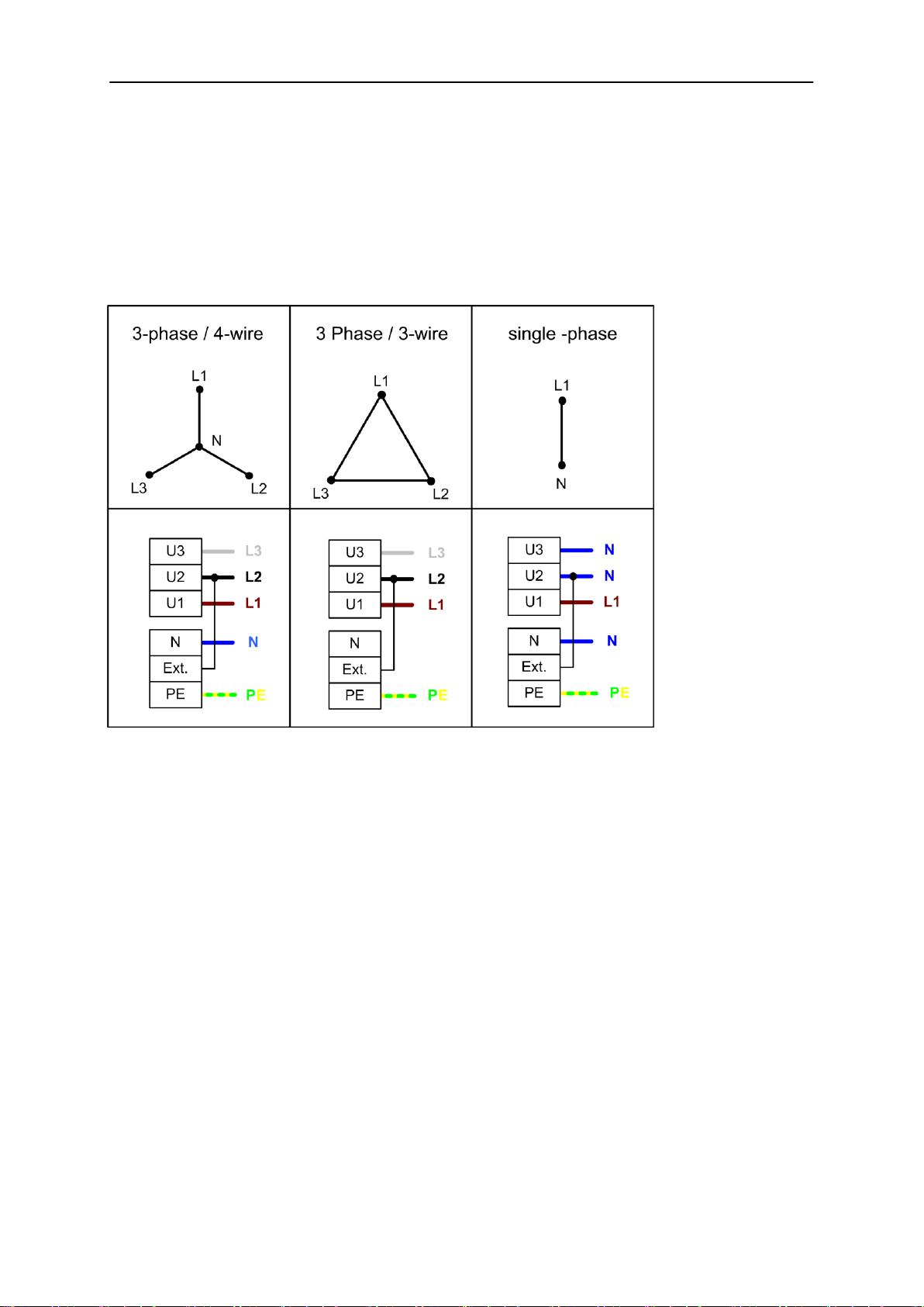
The econ sens+ energy consumption meter can be used with various public power supplies:
3-phase four-wire power system (with neutral conductor)
3-phase three-wire power system (without neutral conductor)
Single-phase power system
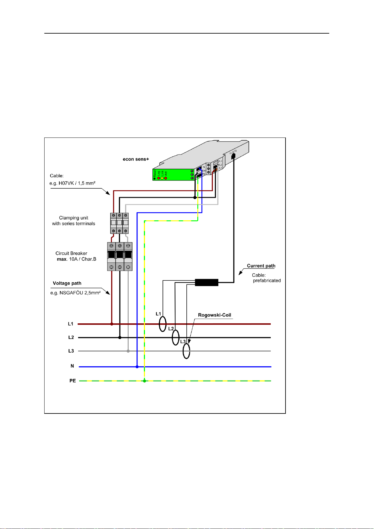
Fig. 7 shows the integration of the econ sens + into a 3-phase 4-wire power system.
The phases L1, L2 and L3 of the voltage path must be protected by means of automatic circuit
breakers to prevent the system from being damaged in the event of a short circuit. A B6 (max. B10)
automatic circuit breaker is recommended. For safety reasons it is preferable to use a short-circuit-
proof conductor (NSGAFÖU) in front of the circuit breakers.
Figure 7: econ sens+ connection diagram to a 3-phase 4-wire power system
Safety Instructions and Warranty Terms 8
Manual econ sens+ Version 1.40
If several econ sens+ devices are installed next to one another it is recommended that you use a
clamping unit with series terminals. As a result it is easier to direct the fused voltage path in parallel to
all devices.
Table 1 shows the terminal assignment of the voltage path terminals for the various types of power
system.
Table 1: Connection diagrams of various power system topologies

Safety Instructions and Warranty Terms 9
Manual econ sens+ Version 1.40
Installing the econ sens + in a 690V grid
The econ sens + can also be used in a 690 V grid (IT-System). It should be noted that a neutral
conductor is required. This is because the power supply of this device is itself designed for voltages on
the primary side to 440Vrms. When connected to a 690 V power connection so the image has to be
used according to Fig. 8.
Installing the current sensors
To install the current sensors (Rogowski coils), wrap these around the conductor that is to be
measured, as shown in Fig. 9. This can be a cable or also a conductor rail.
Insert the free end of the cable into the end piece of the coil until it latches into place. The coil must
form a closed loop around the conductor.
The label on the coil must be aligned in such a way that it points towards the consumer. This ensures
the correct direction of current flow through the coil.
Please also ensure that each sensor matches the corresponding phase of the voltage path (coil L1 to
phase L1, etc.)
Figure 9: Installation of the current sensors
Abbildung 8: Anschlussschema 690 V-Netz
Safety Instructions and Warranty Terms 10
Manual econ sens+ Version 1.40
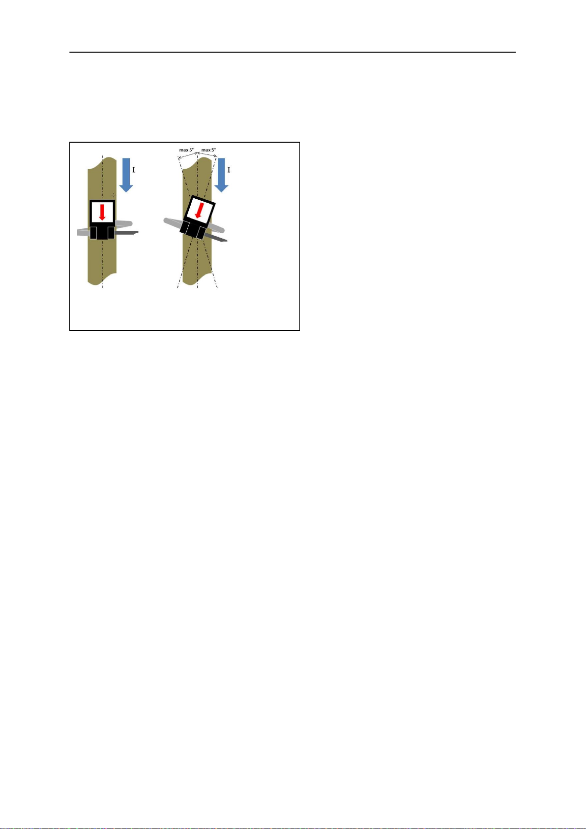
Alignment of the coil with the current flow
If possible, secure the coil round the conductor (cable, conductor rail, etc.) with a tie wrap. Make sure
that the loss angle of the coil is not too large (see Fig. 10).
In the case of loss angles > +/-5°, the relative
error of measurement is also greater and
consequently also the relative deviation of the
measured current and the calculated
parameters (e.g. power).
Figure 10: Loss angle of the current sensors
Safety Instructions and Warranty Terms 11
Manual econ sens+ Version 1.40
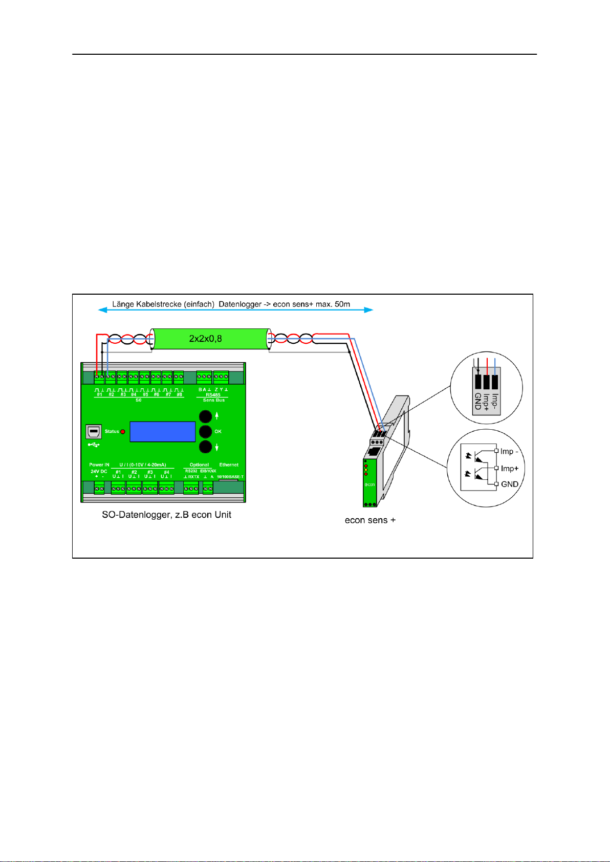
Connecting the data outputs
S0-Interface
The consumption data measured by the econ sens+ is outputted via the pulse outputs Imp+ and Imp-
(open-collector NPN outputs) as a pulse sequence. Each output pulse is 50 ms long and corresponds
to a defined amount of energy in Wh. This can be configured via the web interface. (For details see
“Web Interface” chapter). The default value for this pulse weighting is 10 Wh/pulse, which corresponds
to an output of 100 pulses/kWh.
The pulse outputs are used for the automated capture of the energy consumption values by means of
a data logger, e.g. the Econ Unit. Fig. 11 shows the layout of the pulse interface.
The distance between the data logger and the econ sens + may be amount to max. 50 meter. When
connecting a cable, a shielded cable is recommended *, as Belden YE00820. For shorter distances an
unshielded cable can be used.
* A shielded cable should come in all applications where massive electromagnetic disturbances from the environment is
expected.
Abbildung 11:Belegung der S0-Ausgänge und mögliches Anschlussschema
Safety Instructions and Warranty Terms 12
Manual econ sens+ Version 1.40
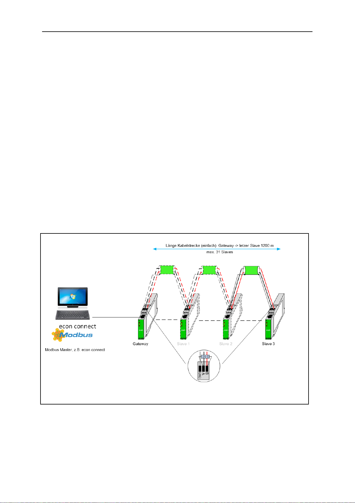
RS485-Interface
The econ sens + supported on this interface the following protocols:
Modbus RTU
Modbus RTU
Via the RS485 Modbus RTU protocol, the values "Modbus / pulses / s submenu " p.17 ff) can be
retrieved according to section.
To use Modbus RTU a Modbus master is required. In a segment of up to 32 devices can be connected
together. For more than 32 devices in a segment repeaters are required. The wiring of components is
a “linear structure”, as shown in Fig 13. Other bus topologies, such as Star shape is not possible.
At the beginning and end of a segment, the cable is terminated with resistors (bus termination). Put
between lines A and B a 120 Ωtermination resistor. As a connecting line between the devices we
recommend a shielded cable 2x2x0, 8, for example, Belden YE00820 or a Cat 5 network cable. The
maximum length is 1200 meters.
Figure 13: Assignment of the RS485 outputs (here with one econ sens+ as gateway)

Safety Instructions and Warranty Terms 13
Manual econ sens+ Version 1.40
Connecting the network
The econ sens+ energy consumption meter has a 100BASE-T network connection for web interface
access. This can be connected to a PC either directly or via a node such as a hub or switch. Connect
the econ sens+ to your hub/switch using a patch cable (1:1) or directly to your PC (using a crossover
cable).
Further information on the IP address settings, etc. can be found in the “Initial operation” chapter.
Modbus TCP
Via the network connection measured values and events (Pro variant) can be accessed via the
Modbus protocol for both versions (S0/RS485). The parameter settings are performed in the Modbus /
pulses / s submenu. The corresponding register addresses can be found in the manual on page 34 ff.
Web Interface of the econ sens+
Accessing the web interface
The web interface is accessed by entering the IP address of the econ sens+ in the address bar of the
web browser (Firefox, IExplorer, GoogleChrome, etc.). The network default settings of the econ sens+
are as follows:
IP address: 192.168.0.1
Subnet mask: 255.255.255.0
Standard gateway: 192.168.0.254
For the web interface to be accessed, ensure that the user PC is in the same network as the econ
sens+. Configure as follows (e.g. under WinXP):
Figure 14:econ sens+ network connection

Safety Instructions and Warranty Terms 14
Manual econ sens+ Version 1.40
Figure 15: Internet protocol properties
1. Under “Start / Control Panel / Network and Internet Connections / Network Connections” double-
click the LAN connection of the network interface card connected to the network.
2. Click the “Properties” button.
3. Select “Internet protocol (TCP/IP)” from the list and click on “Properties”.
4. Activate the options “Use the following IP
address” and “Use the following DNS server
addresses”.
5. Enter the parameters shown in Fig. 10 and
confirm with “OK”.
When the above IP address is entered in the
web browser, the econ-sens+ homepage
should appear.
The settings for Windows 7 are performed in the Network and Sharing Center.
Accessing the web interface in a network with a DHCP server
If the econ sens+ is located in a network in which there is a DHCP server available for automatic
address assignment, it automatically adopts the address assigned to it by this server. You can identify
which address the econ sens+ has been given in the DHCP Server.
Safety Instructions and Warranty Terms 15
Manual econ sens+ Version 1.40
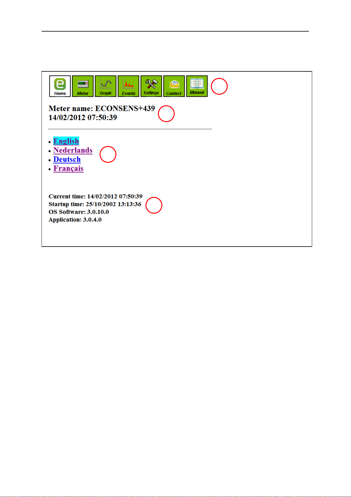
Home menu
On the home screen of the econ sens + you find the following information:
1. Menu bar to navigate the individual menus of the econ sens+
2. Device name and current time/date
3. Language selection menu
4. Information bar
Time/date settings
Start-up time
Operating system version
Application software version
Figure 12: "Home" menu screen
1
2
3
4

Safety Instructions and Warranty Terms 16
Manual econ sens+ Version 1.40
Meter menu
Econ sens+ displays the measured values in tabular form in the Meter menu.
This table is shown in Fig. 17.
The following are displayed: the voltages of the phases L1, L2, L3, the corresponding currents, as well
as the active and the reactive power per phase and the “power factor”(for pure sinusoidal alternating
currents, this is synonymous with the familiar cos phi).
You can refresh the display by pressing the F5 key on your keyboard as required or you can activate
the arrow button next to the word “Actual power”.Then the display will be updated every second.
The vector diagram below the table serves to visualize the phase shift between the voltages L1, L2 L3
and the corresponding currents.
*The “Un”specification below the table indicates the so-called neutral conductor voltage (voltage difference between the neutral
conductor and the protective earth). This is needed for the Events menu, which deals with network analysis. This menu is
however disabled in this software version.
Figure 13: econ sens+ table of measured values
*

Safety Instructions and Warranty Terms 17
Manual econ sens+ Version 1.40
You can also have the voltage and the current on the three phases displayed as a curve by selecting
the Curve option at the bottom left of the screen. (see Fig.18)
Econ sens+ is able to measure and display both the generated and the consumed active power. This
is illustrated in Fig.12.
The consumed active power is shown in the table in blue, while the generated active power with a
negative sign is shown in red. In the above example this means that on phase L1 power is only
consumed and on phase L2 power is only generated.
If power is both consumed and generated at the same time on one phase, econ sens+ shows the sum
of the two.
An example:
With your photovoltaic power system with downstream inverter you generate 1 kW on each of the
three phases L1, L2, L3, at the same time consuming 500 Watt on phase L2 for various household
appliances. Then your table of measured values would look like the table in Fig. 19.
Figure 19: Table of measured values for the example
Figure 18: Current and voltage curves
This manual suits for next models
1
Table of contents
Other Econ Measuring Instrument manuals


Popular Measuring Instrument manuals by other brands


Frankford Arsenal
Frankford Arsenal INTELLIDROPPER 1082250 user manual

Stanley
Stanley Fatmax TLM330S user manual

Agilent Technologies
Agilent Technologies OmniBER 720 user guide

HACH LANGE
HACH LANGE Pocket Colorimeter II user manual

Nidec
Nidec FG-7000TA Operation manual

Milwaukee
Milwaukee REDLITHIUM L4 3PL Operator's manual


