Econo CWM Series User manual

www.econo.nl
Manual heatpump model Econo - CWM

- 2 -
Index
1.
Product introduction ....................................................................3
.1.1
Features .................................................................................................3
.1.2
Definition of specification.....................................................................4
2.
Technical data................................................................................4
.2.1
Specification parameter .........................................................................4
.2.2
The figure of working principle ............................................................6
.2.3
Figure dimension...................................................................................7
3.
Installation Instruction.................................................................6
.3.1
Installation .............................................................................................6
.3.2
Water system installation chart............................................................ 11
.3.3
Electrical diagram................................................................................12
.3.4
System test...........................................................................................14
4.
Parameter settings ..................................................................... 15
5.
Maintenance ............................................................................... 26
6. Malfunction protection and code………………………………29

- 3 -
1
Product introduction
.1.1
Features
Convenient operation
Microelectronics control, all temperature settings are set by manufacturer. System tests water
temperature and adjust water temperature automatically, all user needs to do is just to press
ON/OFF button. System finishes the other operation automatically.
Excellent performance
Adopt world famous components, and the best match of system design. Scroll compressor
with high EER and low noise. High efficient heat exchanger insures the utmost using of system
capacity. Professional air conditioner water pump insures smooth quiet operation.
Models adopting two compressors system may operate with one compressor on condition of
partial load, energy saving design.
Easy to install
The system is designed with full consideration of insuring installation as easy as possible.
Refrigerant circle is a sealed complete system finished by manufacturer. No needs for users to
connect copper pipes or refrigerant charging. Hydraulic circle of system can be connected to
hydraulic terminals by two tubes.
Operating protection
System is designed with over voltage, under voltage, over load protection to insure safe
operation. The microelectronics controller can start or switch off the machine by judging the water
temperature. If the water temperature is lower than designed water temperature, the machine will
be switch off to avoid freezing. The microelectronics controller can also supervise the status of
components. Malfunction occurred would be transmitted to the controller and displayed through
malfunction code.
Flexible applicability
Compact design. System can run at conditions high ambient temperature or low ambient
temperature with high EER.
Convenient for maintenance.

- 4 -
Suppose system is stopped by malfunction, special malfunction code will be displayed. The
cause may be found out easily.
.1.2
Definition of specification
The specification of heat pump are defined according to following rules:
C W M-15 X B
Heati ng power
Heat Source code
Company code
Desi gn code
Product t ype
Product desi gn code
Picture 1
2
Technical data
.2.1
Specification parameter
Table 1
Heat pump model CWM- 15XB
kW 15.0
Rated heating capacity kcal/h 12897
Heating power Input kW 3.2
Heating running
Current A 6.55
Sanitation
heated
water
condition
COP kW/kW 4.68
kW 11.5
Rated cooling capacity kcal/h 9872
Rated water flow
(air-condition)T/h 1.98
Equipment performance
Cooled
water
condition(a
ir-conditio
n)
Cooling power Input kW 2.5

- 5 -
Heat pump model CWM- 15XB
Cooling running
Current A 4.4
E.E.R kW/kW 4.6
kW 13Rated heating capacity
(air-condition)kcal/h 11178
Rated water flow T/h 2.23
Heating power Input kW 3.5
Heating running
current A 7.0
Heated
water
condition(a
ir-conditio
n)
COP kW/kW 3.3
kW 9.7Average cooling
capacity kcal/h 8342
Rated water flow T/h 1.7
kW 12Average heating
capacity kcal/h 10320
Average power Input kW 2.6
Average running
Current A 4.4
Alliance
for cool
and heat
conditions
Synthesis COP kW/kW 8.3
Max. Running Current A 12
Power source V/Ph/H
z 380/3N/50Hz
Compressor type Scroll
Charged refrigerant R417A 3
Connection pipe RC 32
Noise level dB(A) 60
W mm 680
D mm 1020
Dimension
H mm 770
Net weight kg 180
Enclosure Class IPX4
Date,S/N: See circuit
diagram
Note:
::
:1. Sanitation heated water condition: Rated environment temp.18/23Deg.C,heating water
temp.15/55Deg.C.
Cooled water condition (air-condition): Rated environment temp.18/29Deg.C,cooling water
temp.12/7Deg.C.
Heated water condition (air-condition): Rated environment temp.15Deg.C,cooling water
temp.40/45Deg.C. The same to water flow in the summer.
Alliance for cool and heat conditions: Heating water temp.15/55Deg.C. cooling water
temp.12/7Deg.C.
2.Manufacturer tests the noise level showed above in lab. The noise level of installed unit could

- 6 -
be different with above data due to the surrounding condition.
3. Manufacturer keeps the right to change technical data due to technical improvement.。
.2.2
The figure of working principle
Gr ound souce wat er out l et
Gr ound sour ce wat er i nl et
A/ C wat er i nl et
A/ C wat er out l et
Heat i ng wat er out l et
Heat i ng wat er i nl et
Picture 2
compressor Four-way valve tube in tube heat exchanger
pressure drop switch Pump Filter
⑦liquid tank ⑧Thermal Expansion Valve ⑨gas-liquid segregator
Table 2

- 7 -
.2.3
Figure dimension
A/C water inlet
A/C water outlet
Ground source
water outlet
Ground source
water inlet
heat water outlet
heat water inlet
Picture 3 CWM-15XB
3
Installation Instruction
.3.1
Installation
The installation must be done by qualified professionals. Make sure the
The installation must be done by qualified professionals. Make sure the The installation must be done by qualified professionals. Make sure the
The installation must be done by qualified professionals. Make sure the
installation match
installation matchinstallation match
installation matching
inging
ing the following conditions.
the following conditions. the following conditions.
the following conditions.
The selection of installation location
The installation location must match the following conditions:
Make sure the installation environment is open surrounding and good ventilation.
The machine may be installed above the ground, keeping enough space between the bottom
plate and ground. In order to assure draining water effectively. And the bracket must has enough
carrying capacity;
Hydraulic circle charged with clean water, no dust or oil. Soft water is recommended;
Make sure that the unit operating noise will not impact the living of neighbor.
The unit must be installed firmly, and the bottom of unit must be horizontal (the gradient must
be less 5 degree)
Keep enough space between the machine and wall. It is convenient for unit's repairment and
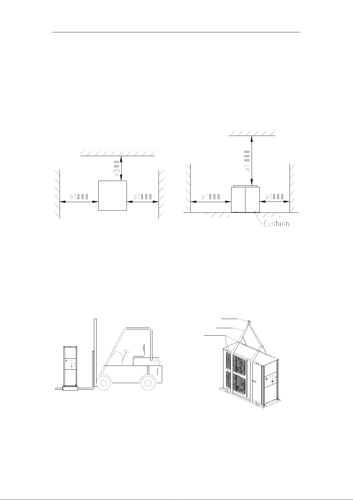
- 8 -
maintenances; and also you shouldn't lay the pipelines and top-ray tubes on the unit. The
suggested installation location as below. (Unit: mm)
Unit should have adequate drainage measures in the vicinity, so that the system stops running or
maintenance of the water drainage system.
Picture 4
②
②②
②
Attention of moving machine
Fork lift stacker or crane is suggested to move the machine;
The surrounding ambient temperature of unit during transportation must be among –25 to 55
Picture 5
While suspending the machine, crane cable must be tie to machine tightly, keeping the machine
horizontal.
disassemble the ground bolt in the pallet after the machine is well located, and take the pallet
pr oe c t i ng c h i p bo ar d
c r a n e c ab l e
c r a n e hoo k

- 9 -
aside。
Fixation
Rubber gasket is recommended to reduce vibration and noise while rivet the bottom plate.
④Water pipe connection
Heated water pipe must be packed with thermal isolation material to avoid thermal capacity loss
or dew dropping.
Inlet connection pipe must be equipped with a water filter.
The connection water pipes must be well matched (refer to specification parameters sheet).
PVC or PP-R pipe is recommended to use as water pipe.
Hot water pipe must be equipped with water pump 、Soft tie-in、a water filter、One way valve、
Flow meter、exhaust valve、Drain valve、Shutoff valve and so on。
Cooling pipe must be equipped with Soft tie-in、a water filter、One way valve、Flow meter、
Drain valve、Shutoff valve ,And then connected to underground inlet/outlet water pipe.
Drain cock should be installed at the highest point of hydraulic circle. After the hydraulic circle
is connected completely, exhaust air inside hydraulic circle.
Drain valve should be installed at the lowest point of water pipe.
Please note:
The appliance shall be installed in accordance with national wiring regulations.
Please make sure the following working conditions. the voltage can not be more or less than
10% of rated voltage and the frequency can not be more or less than 1% of rated frequency. The
height above sea level should be less than 1,000 meters.
Working water temperature available from 8~50, maximum water pressure 10 bar.
Wires must be connected according to the instruction of electrical connection diagram.
Also an all-pole air-break switch is needed and the pole clearance should be more than 3mm.
The ground wire must be well connected. Ground wire can’t be connected to coal gas pipe,
water pipe or telephone wire.
Drain electricity protection switch is needed for the system. No drain electricity protection
- 10 -
switch may cause electrical shock.
The operation handle of power switch is suggested to be black or gray, and it can be fixed at
OFF status. The installation location of power switch is suggested among 0.6 to 1.7 m. electrical
short circuit protection is needed.
If the supply cord is damaged, it must be replaced by the manufacturer or its service agent or a
similarly qualified person in order to avoid a hazard.
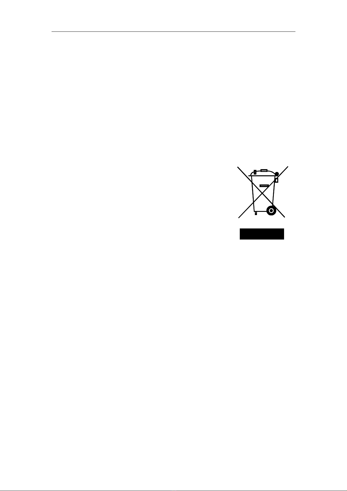
dispose
Do not dispose this product as unsorted municipal waste. Collection of such waste separately for
special treatment is necessary.
Meaning of crossed-out wheeled dustbin: Do not dispose of
electrical appliances as unsorted municipal waste, use separate
collection facilities.
Contact you local government for information regarding the
collection systems available.
If electrical appliances are disposed of in landfills or dumps,
hazardous substances can leak into the groundwater and get into the
food chain, damaging your health and well-being.
When replacing old appliances with new ones ,the retailer is legally obligated to take back your
old appliance for disposal at least free of charge.
It is prohibited to dispose of this appliance in domestic household waste. for disposal there are
several possibilities:
a) The municipality has established collection systems, where electronic waste can be disposed of
at least free of charge to the user.
b) When buying a new product , the retailer will take back the old product at least free of charge.
c) The manufacturer will take back the old appliance for disposal at least free of charge to the
user.
d) As old products contain valuable resources, they can be sold to scrap metal dealers.
Wild disposal of waste in forests and landscapes endangers your health when hazardous
substances leak into the ground-water and find their way into the food chain.

- 11 -
Warning
.3.2
Water system installation chart
⑥
⑥
②
①
③
⑤④
⑥
⑥
⑩
④
⑧
Out l et heat ed water
I nl et wat er
⑥
⑥
⑥
⑥
⑤
⑤
10
Indoor
terminal
Cooling Tower
12
12 45
5
⑥⑥
Storage
water
tank
Expansion Tank
15
13
14
15
13
13
Picture 6
Table 3
1 Ground Source Heat Pump
Water Heater 2 Soft tie-in 3 Pressure drop switch 4 One way valve
5 Pump 6 Shutoff valve 7 Water supply valve 8 Water valve
9 Back valve 10 Y type filter 11 Water tanks 12 Thermometer
13 Flow Control Valve 14Safety valve 15 Pressure switch
Hydraulic circle is recommended while installing Water Source Heat Pump Water Heater .
Warning
Any abnormal accident, such as burning smell, switch off the machine immediately. Contact
!
Warning
It is forbidden to clean the hydraulic circle by water pump inside system.
!
Warning
Make sure the machine has been power connected over 12 hours before starting the system. Otherwise,
machine could be damaged.
!

- 12 -
The installation of hydraulic circle can be finished according to above chart.
NOTES:
::
:
A、
、、
、Please do exhaust the air in water system before running the machine, if you completely finished
the circulating water system piping.
B、
、、
、The water flow switch must be installed at the straight pipeline section of the same level, from
the elbow, valves and other pieces of partial resistance to more than 5 times the diameter.
C、
、、
、The pipe must be insulated closely in order to improve cooling (heating) effect and energy
conservation.
D、
、、
、The take-over of this unit must be installed with drainpipe to make it convents to drain water
inside the unit and prevent it from freezing.
.3.2 Electrical diagram.

- 13 -
TRON2
TRAN1
C
XT
T
S
R(L)
DI P swi tch
Wat er
sour ce
pump
KM2
U1 V1 W1
Heat
wat er
pump
Ai r swi t ch
COMP
R S T N
N
W1
CCH1
11
V1U1
KM1KM3
A/ C
wat er
pump
KM4
R(L)
10
①
①①
①unit wiring
Model Power Voltage (V) Power wire(
mm
2
)
Allowed max
current (A)
Allowed leakage
current
CWM-15XB 380V/3N/50HZ 342-418V ≥4.0
12A 3mA
②
②②
②
attentions of wire connecting
All wires must be well connected.

- 14 -
All wire should avoid touching refrigerant tube. If it is not avoidable, vibration protection and
isolation must be well done.
All wire no touch to compressor or any other kinetic components.
When the heated water flow switch and ground water flow switch is unused, the 10 and 11
terminal on the bank terminal should be short-joined,or the unit can't start.
When the high water level switch、in water level switch and low water level switch is unused, the
12、13、14 and 15 terminals on the bank terminal should be short-joined,or the unit can't start.
.3.3
System test
○
○○
○
1Checking items before test run of system
1)、Seal test to make sure system is well sealed.
2)、Power source checking to make sure required voltage and current are available.
3)、Pressure inside hydraulic circle reaches to operating pressure(1-3)kgf/cm
2
。
4)、Make sure hydraulic system inside is clean and no jam.
5)、make sure hydraulic circle is fully filled with water and no air inside.
6)、Check to make sure all valves are switched on, well thermal isolated.
7)、Make sure all electrical wires are connected correctly according to wiring instruction, and wiring
screws are driven properly.
8)、Exhaust the air inside hydraulic circle by manual drain cock in hydraulic tube and drain cock on the
water pump.
9)、Check if there is visual damage caused during transportation.
10)、make sure all wiring correct.
②
②②
②
Commissioning
1)、Make sure all above checking items are passed.

- 15 -
2)、Open controller cover, then connect the power source wires. If the power source is three phases,
check the phase order immediately. Red lamp on controller board will light while phase order is correct.
Check if water pump works smoothly. If there is scream from water pump, it means there is air inside
the water circle. In this case, stop the machine and exhaust air inside water circle. Then start machine
again. The compressor will start to run 3 minutes after the system is switched on. Check if compressor
run at right direction.
3)、Check if there is unusual noise from system by listening. If there is, switch off the machine and
check system. If no unusual noise, let system running.
4)、If all checking items passed, keep system running.
5)、At heating mode , if water tanks temperature≤45, compressor starts to work. The compressor stop
working until the water tanks temperature increase to 50.
6)、Check the temperature difference between return water temperature and outlet water temperature of
outdoor unit. Normally, the temperature difference should be less than 6. If the temperature difference
is over 6, check if water flow match designed standard.
7)、All hydraulic circle filters must be cleaned after finishing test run.
③
③③
③Normal operation:
::
:
Heating running process: Start the unit---pump running--- Detection of flow
switch---Compressor running (When disconnected from the low water level, the solenoid valve will
open to compensate water)
Water level control: in cycle mode,when disconnected from the low water level, the unit Stop
running,the compressor is permitted running the circle when the switch of low water level is pull in,
when the low water level switch is disconnected, then the power begins to compensate Water. At
the same time stop provide water for the pump.. When tank temperature is lower 3, the tanks begin
to detect the temperature, if the tank temperature is higher than the setting temperature, the
compensate water valve would work for water-filled, If the tank temperature is 3lower than the
setting temperature, it would stop compensate water and power off, At the high-water absorption time,
it stops water supply. When the high-level is broken up but the mid-water level is running it won’t

- 16 -
supply water, on order to avoid frequent moving of compensating valve.
In Direct thermal mode, when the mid-water level is disconnected, the host will Open the water
valve, heat pump thermostat begins to work. If the thermostat switches pull in, the host would press
and the fan would work and the circulating water pump would shut down. The same for the
high-water absorption mode, thermostat stops working. At high water absorption time, when water
temperature is 5lower than the setting temperature, it will enter the heating circulation and pumps
circulation, compressors and fans will run, the compensating water valve will shut down, and the
thermostat won’t work; when the low water level is disconnected, the pumps won’t supply water and
electric heating begins. At the low-water level absorption time, when the water temperature is lower
than the setting temperature limitation, it will take the priority for circle heating.
When the supply water valve is turned on, if the high-water level is disconnected and the tank
water temperature is lower than -3(initial setting)then the tank would not compensate water. If the
tank water temperature is higher than setting value then it would compensate water and the
high-water level would last pull-in water 2 minutes before shut down the compensating water
valve( when there is a temperature control the supply of water).
If power up for the first time, it is necessary to circulate pumps after lower-water level absorbs,
then the compressor would run.
When the unit is running, the circulating water pump opens. When the unit stops, the circulating
pump will stop operation 30 seconds later.
Backwater Solenoid valve runs according to water temperature detection. When the return water
temperature is higher than the setting temperature, the solenoid valve will stop return water. When
the return water temperature is lower than setting temperature, then the valve will open to keep the
water supply pipe preserving hot water for a long time.
You can choose water moods of compulsory and time, when the water temperature is over 40,
press the "WATER SUPPLY" key, or it meets the time requirement and it will supply the water,
When it is supplying the water, pressing "WATER SUPPLY" key, or it meets the stop water supply
requirement, water supply will stop. When the water temperature is below 40, it won’t supply
water.

- 17 -
4
Panel operation
Settime
Time
△
△
▽
Chec Model
Temp.
Set

- 18 -
1) On/Off function
□ Press“on/off”button,the unit starting,the pilot lamp is lighting;
□ Then press“on/off”button,the unit stop,the pilot lamp put out。
□ “On/off” is all storied date。
2) Model conversion
□ Press“Model”button,choose the required model,“Refrigeration”or“Heating”
model. “Refrigeration and heat water” “Heating and heat water” “ heat water”
model.
□ “Refrigeration” displays snowflake symbol.
□ “Heating” displays sun symbol
□ When the unit is off, the “Refrigeration” and “Heating” mode display the A/C
temperature.“Heat water”mode display the temperature of tank, “Refrigeration”
and “Heat water”mode, and “Heating”and “Heat water”modes will be display
the A/C temperature and the temperature of tank by turns.
□ The unit is on, at the “Refrigeration”and “Heating” mode, the first two shows

- 19 -
air-conditioning return water temperature, the after two display air-conditioning
temperature setting.
□ “Refrigeration”and “Heat water” mode, “Heating”and “Heat water”mode, the
first two shows air-conditioning return water temperature and the tank
temperature by turns, the after two display air-conditioning temperature and the
tank temperature setting.
□ Water tank when water temperature symbols, air-conditioning temperature, no
water symbol
□ There is water symbols display the temperature of water tank, but display A/C
water temperature, there is not.
Refrigeration heating Refrigeration and heat water
Heating and heat water heat water
3)
Set time
on/off
i. Set 〖b7〗is for 0 which shows compares’ timing.
□ In the case of running,press“
Set time
”button,shutdown
Set time
;
□ In the case of shutdown,press“
Set time
”button,start
Set time
;
□ Press“
Set time
”button,then hour time flashing;
□ Press“time▽△”button,adjust hour of regular time

- 20 -
□ Then press“
Set time
”button,minute time flashing;
□ Press“Time▽△”,adjust minute of regular time.
□ Then press“
Set time
”button,
Set time
set
s finished.
□ Then press“
Set time
”button,canceled
Set time
.
ii. Set 〖b7〗is for 1 which shows circulation timing.
□ Press“Set time”button,then hour time flashing,begin set
Parameter Name Unit No.
Default
setting
MAX MIN
Refrigerating P1 12 30 〖b6〗
A/C Heat water
set temperature
P2 40 〖b7〗 25
Setting
temperature heat
water recovery
P3 55 〖b8〗 10
Combine timing/
Cycle timing
selection
P4 0
1: Cycle
timing(Cycle
every 24 hours
operation)
0: Combine
timing(Within 24
hours once a valid)
Set time
-open′time.
□ Press“Time▽△”button, adjust hour of regular time
□ Then press“
Set time
”button,minute time flashing
□ Press“time▽△”button,adjust minute of regular time
This manual suits for next models
1
Table of contents
Other Econo Heat Pump manuals


Popular Heat Pump manuals by other brands

Pentair
Pentair UltraTemp-E installation guide

Immergas
Immergas AUDAX PRO 4 V2 Instructions and warnings

Dimplex
Dimplex LI 8MSR Installation and operating instructions

Amana
Amana American Pride ACNF Series manual

EMI
EMI Volts/HZ/pH Installation & operation manual

salmson
salmson SIE Installation and starting instructions


Heat Controller
Heat Controller SMH 24 installation instructions

Alpha
Alpha E-Tec 33 Installation and commissioning instructions

Dimplex
Dimplex LI 11AS Installation and operating instructions

Enerflow
Enerflow Eskom ERHP-SU08 user manual

Rotex
Rotex RBLQ05CAV3 installation manual

Riello
Riello AARIA START Installation and technical service instructions