Economite RE32 Quick guide

MIDCO International Inc.
4140 WEST VICTORIA STREET, CHICAGO, ILLINOIS 60646 / (773) 604-8700 FAX: (773) 604-4070 / http://www.midco-intl.com
The ECONOMITE Model RE32 intermittent spark ignition conversion burner is adaptable to most gas utilization equipment,
including gravity and forced circulation furnaces and boilers, and is particularly recommended for horizontal and downdraft gas
utilization equipment since it needs no draft to maintain a pilot. Power burner design makes it perfectly suited for oil burner
replacement.
Do not store or use gasoline or other
flammable vapors and liquids in the
vicinity of this or any other appliance.
WHAT TO DO IF YOU SMELL GAS
● Do not try to light any appliance
● Do not touch any electrical switch;
do not use any phone in your building.
● Immediately call your gas supplier
from a neighborÕs phone. Follow the
gas supplierÕs instructions.
● If you cannot reach your gas
supplier, call the fire department.
Installation and service must be
performed by a qualified installer,
service agency or the gas supplier.
INSTALLATION AND
SERVICE INSTRUCTIONS
ECONOMITE MODEL RE32
Gas Conversion Burner
PRINTED IN U.S.A. 197
8470-01
WARNING: If the information in
these instructions is not followed
exactly, a fire or explosion may
result, causing property damage,
personal injury, or death.
In the United States, installation must conform with local codes or,
in the absence of local codes, with Installation of Domestic Gas
Conversion Burners, ANSI Z21b-latest edition, and National
Fuel Gas Code, ANSI Z223.1-latest edition,available from
American National Standard Institute. Further reference should
be made to the recommendation of your fuel supplier.
NOTE: Any additions, changes, or conversions required in order for
the gas utilization equipment to satisfactorily meet the application
needs must be made by a MIDCO distributor (or other qualified
agency) using factory specified and approved parts.
In Canada, installation must conform with local codes or, in the
absence of local codes, with Installation Codes for Gas Burning
Appliances and Equipment, CGA Standard CAN/CGA 1-B149.1
or 2. When the conversion burner is used on Forced Air Central
Furnace, the two yellow and black warning labels in the literature
envelope shall be attached in accordance with Installation Code,
CGA Standard CAN/CGA 1-B149, Clause 5.4.4.4. Further
reference should be made to the recommendation of your
fuel supplier.
INSTALLER: Inform and demonstrate to the
user the correct operation and maintenance of
this gas utilization equipment. Inform the user
of the hazards of storing flammable liquids
and vapors in the vicinity of this gas utilization
equipment and remove such hazards. Affix
this manual adjacent to the conversion burner.
CODE COMPLIANCE IS THE SOLE
RESPONSIBILITY OF THE INSTALLER.
USER: Retain this manual for future reference.
If other than routine service or maintenance
as described in this manual is required,
contact a qualified service agency. DO NOT
ATTEMPT REPAIRS. An inadvertent service
error could result in a dangerous condition.
SAFETY INFORMATION TERMS: The following terms are used to identify hazards, safety precautions or special notations and have
standard meanings throughout this manual. When you see the safety alert symbol and one of the safety information terms, as
shown below, be aware of the hazard potential.
DANGER: Identifies the most serious hazards which will result in severe personal injury or death.
WARNING: Signifies a hazard that could result in personal injury or death.
CAUTION: Identifies unsafe practices which would result in minor personal injury or product and property damage.
ANSI Z21.17
CONVERSION
BURNERS

around door frames, to prevent leakage into or out of the
combustion chamber.
■ The access or firing door should open easily to relieve
pressure. If positive latches exist, they should be modified to
permit easy opening; a spring loaded door holder is
recommended.
■ On all boilers, make certain the pressure relief safety valve is
in good operating condition.
III COMBUSTION CHAMBER
A combustion chamber liner is normally required to protect
non-heat transfer surfaces and to provide a radiant bed for
rapid heat transfer to the primary surfaces of the heat
exchanger. In most cases an existing oil burner combustion
chamber liner can be used, if in good condition.
■ In the case of wet base boilers, where the entire combustion
chamber is comprised of heat exchange surfaces and no
combustion chamber liner was provided for oil firing, a liner is
usually not required for the ECONOMITE. However, a liner or
target wall may be necessary if the combustion chamber is
unusually short, in order to avoid excess flame contact on the
heat exchanger walls or flueways.
■ If a built up combustion liner is required, use 2300oF
minimum insulating material.
■ The opening in the combustion chamber must fit the burner
tube. If an existing chamber with an oversized opening is to be
used, fill the remaining space around the tube with refractory
material and seal air tight.
NOTE: In no case should the burner tube be allowed to extend
into the chamber proper; it must be set flush to 1/4" short of the
inside surface, because high combustion chamber
temperatures will cause premature pilot deterioration.
■ Burners are shipped with the burner tube at its fully extended
length of 61/4 inches. To reduce the tube length, complete the
following steps (see Figure 1):
1. Uncover the Burner Tube Clamp access port located on the
lower right side of the burner box (under motor),
adjacent to the mounting flange.
2. Turn the exposed screw counter-clockwise to loosen
the Burner Tube Clamp.
3. Turn the Pilot Tube Clamp Nut (see Figure 1)
counterclockwise, to loosen the Pilot Tube.
4. Push Burner Tube in to desired length and tighten
Burner Tube Clamp and recover access port.
5. Locate the retention plate at least 7/8 inch but not more
than 13/8 inch from the end of the burner tube and tighten
the Pilot Tube Clamp Nut.
6. Cut the Pilot Tube to the appropriate length and
reattach tube fitting using compression sleeve supplied in
spud-bag.
FIGURE 1 Burner Tube Adjustment
-2-
SPECIFICATIONS
NATURAL or PROPANE Gas
AIR DELIVERY(Approx. Air Delivery at Zero Draft).....62SCFM*
MAXIMUM FIRING RATE**................................300MBH***
MINIMUM FIRING RATE**...................................50MBH***
TUBE DIAMETER................................................4 inches
TUBE LENGTH......................................21/2 - 61/4 inches
MINIMUM COMBUSTION CHAMBER SIZE
300 MBH...................................7" W x 11" L or 10" dia.
50 MBH.....................................6" W x 10" L or 9" dia.
GAS PRESSURE REQUIRED
NATURAL..........................................4.0" to 14.0"W.C.
PROPANE.........................................4.0" to 14.0"W.C.
STANDARD VOLTAGE..........120 Volts.............60 Cycle
PILOT SAFETY.........................Electronic, 100% shut-off
MAIN AUTOMATIC VALVE...........4 Function Redundant
*SCFM = Standard Cubic Feet/Minute
**All Ratings Based on 1000 BTU/Cu. Ft. NATURAL, 2500
BTU/Cu. Ft. PROPANE at Sea Level Derate burner for
altitudes over 2,000 feet by 4% for each 1,000 feet above
sea level
***1 MBH = 1,000 BTU/Hr.
One gallon fuel oil = 140,000 BTU/Hr.
PART 1 INSTALLATION
CAUTION: The ECONOMITE RE32 is not intended for
outdoor installation and must be protected from excessive
moisture. Provide adequate clearance for service and
proper operation.
I VENTILATION
If the former automatic oil burner gave trouble-free operation, it
is probable that the gas utilization equipment area has sufficient
infiltration of air for combustion and dilution of flue gas.
Nevertheless, the area must be checked:
■ Open basement or utility areas of normal construction,
without storm windows or tight doors, will generally allow
sufficient air infiltration. However, if the gas utilization
equipment is located in a tight or separate room, ventilation to
an open area as described above will be required. Install two
permanently open grilles, each sized on the basis of one
square inch free area per 1,000 BTU (but not less than 100
square inches) of the total input ratings of all gas utilization
equipment in the combined space. One grille should be located
within 12 inches of the ceiling, the other within 12 inches of the
floor.
■ If the gas utilization equipment is located in an area of
unusually tight construction, or if an exhaust fan, kitchen
ventilation system, clothes dryer and/or fireplace is installed in
the building, provision must be made for an outside air supply
near the gas utilization equipment area. Install permanently
open grilles sized at not less than one square inch free area per
4,000 BTU of burner input. When ventilating through horizontal
ducts, grilles should be sized at not less than one square inch
free area per 2,000 BTU of burner input. In any case, the
minimum dimension of rectangular air ducts shall not be less
than 3 inches.
■ In Canada, for detailed ventilation requirements, refer to
standard CAN/CGA 1-B149.1 or .2 and/or local codes.
II PREPARATION OF THE GAS
UTILIZATION EQUIPMENT
■ Clean the gas utilization equipment heat exchanger interior,
combustion chamber and flue connections. Remove all
adhering tars, scale, dirt and soot. Inspect equipment for actual
leaks and/or potential leaks.
■ Cement all joints, including those in the equipment base and

WARNING: BURNER CABINET MUST BE MOUNTED
IN ORIENTATION SHOWN IN FIGURES 2 AND 3.
ANY OTHER MOUNTINGS MAY CAUSE DANGEROUS
CONDITION, AND WILL VOID BURNER WARRANTY AND
AGENCY APPROVALS.NON-STANDARD ARRANGEMENTS
MAY BE AVAILABLE FOR SOME MODELS; CONSULT
FACTORY FOR DETAILS IF REQUIRED.
■ Before permanently setting the burner in place, check
retention plate and pilot assembly to make sure they are free
of foreign materials.
IV CHIMNEY, VENT CONNECTOR, AND
DRAFT CONTROL
WARNING:The chimney shall be inspected for unsafe
conditions such as deteriorated masonry and excessive
soot or other blockage or potential blockage. Installation
must conform with local codes or in the absence of local
codes with ANSI Z21.8-latest edition and NFPA, ANSI Z223.1
- latest edition
WARNING: THE VENT CONNECTOR SHALL NOT BE
CONNECTED TO A CHIMNEY ALREADY VENTING SOLID
FUEL BURNING EQUIPMENT, AN INCINERATOR OR AN
OPEN FIREPLACE.
■ The Vent Connector shall be made of non-combustible
corrosion resistant material capable of withstanding the vent
gas temperature produced by the gas utilization equipment and
of sufficient thickness to withstand physical damage.
■ The Vent Connector shall be as short as possible. The
entire length shall be readily accessible for inspection, cleaning
and replacement.
■ The length of horizontal uninsulated Vent Connector
between chimney and a single gas utilization equipment shall
not exceed 75% of the height of the chimney above the
connector, or 100% if the Vent Connector is insulated.
Maximum Input Flue Pipe Diameter
64 MBH 4"
100 MBH 5"
143 MBH 6"
195 MBH 7"
225 MBH 8"
300 MBH 9"
TABLE 1: Recommended Flue Pipe Sizes
Source: ANSI Z21.8A-1990, Installation of Domestic Gas
Conversion Burners. For Other Applications, Consult
Appropriate Standards.
■ The Vent Connector shall be installed so as to avoid turns or
other construction features which create excessive resistance
to flow of vent gas. It shall be installed without any dips or sags
and shall slope upward at least 1/4" per foot.
■ A manually operated damper shall not be placed in the Vent
Connector or chimney of any gas utilization equipment.
■ The Vent Connector shall be firmly attached to draft hood
outlets and flue collars. Joints between sections of connector -3-
FIGURE 2 Dry Base Boiler With Combustion Chamber
Liner (Furnace Construction is Similar)
FIGURE 3 Wet Base Boiler with Unlined
Combustion Chamber
FIGURE 4 Draft Hood
FIGURE 5 Barometric Dampers
Figure 4 and 5 : Copyright by the American Gas
Association. Used by permission of the copyright holder.
piping shall be fastened by sheet-metal screws or other
approved means. The Vent Connector shall be supported for
the design and weight of the material employed to maintain
clearance and prevent physical damage and separation of
joints.
■ A draft hood or a barometric draft regulator shall be installed
in the same room or enclosure as the equipment in such a
manner as to prevent any difference in the pressure between
the hood or regulator and the combustion air supply. In no
case shall the relief opening of the draft hood or barometric
draft regulator be located at a point lower than the top of the
highest flue passage in the equipment.
■ Gas utilization equipment requiring controlled draft may be
equipped with a listed double acting barometric draft regulator
installed and adjusted in accordance with the manufacturerÕs
instructions if approved by local codes.
■ A device which will automatically shut off gas to the burner in
the event of sustained backdraft is required. It shall be of the
listed manual reset type and installed and adjusted by a
qualified service technician in accordance with the
manufacturerÕs instructions.

-4-
V ELECTRICAL
Installation wiring and grounding of the burner must conform to
local codes, or, in their absence in the United States to
National Electric Code, ANSI/NFPA No. 70-1 latest edition; in
Canada, to Canadian Electrical Code Part 1, CSA Standard
C22.1.
■ Use 14 gage copper wire for line voltage wiring. Be sure to
hook up to permanently live circuit. Provide a fused on-off dis-
connect switch carrying a minimum 3 amp fuse.
■ The frame of the burner should be well grounded. A terminal
is provided on the strip for positive grounding.
■ Confirm that the polarity is correct -- hot wire to strip terminal
1, neutral 2 -- and that the neutral line is not subject to induced
low voltage (check 2to earth ground) from other equipment, as
that can cause the flame safeguard to malfunction.
■ Each installation must include suitable limit control(s).
Existing oil burner combination operating and limit controls are
normally NOT SUITABLE for gas burner use.
■ Set the thermostat heat anticipator for the total current draw
handled by the thermostat. The current draw of the Economite
24V operating circuit is 0.9 amps.
CAUTION: Label all wires prior to disconnection when
servicing controls. Wiring errors can cause improper
and dangerous operation. Verify proper operation after
servicing.
10
130
200
275
300
300
TYPE OF
GAS
NATURAL
PROPANE
NATURAL
PROPANE
NATURAL
PROPANE
NATURAL
PROPANE
VI PIPING
CAUTION: The available gas pressure should be within
the limits shown in the SPECIFICATIONS section.
Excessive pressure will damage Combination Valve and
Regulator. If the supply pressure exceeds the 14.0" W.C.
maximum, a suitable intermediate main regulator rated for
main and pilot loads must be installed ahead of the Main
Manual Shut-Off Valve shown in Figure 7.
■ The burner gas supply piping should branch off from the
main line as close to the gas meter as possible. Do not connect
to the bottom of a horizontal section. Use new black pipe and
malleable fittings free of cutting and threading burrs or defects.
■ Provide a sediment trap, union and 1/8" pressure tap in
piping close to burner as shown in Figure 7.
■ Use pipe joint compound approved for use with Liquid
Petroleum Gases.
■ Piping must comply with local codes.
■ To obtain the maximum firing rate of 300 MBH, the gas
supply piping must be sized to provide a minimum of 4.0" W.C.
pressure to the inlet of the combination valve when the burner
and all other gas utilization equipment are on. For a firing rate
of 225 MBH or less, 3.5" W.C. inlet pressure is sufficient.
■ When selecting the burner supply pipe size per Table 2, the
permissible pressure drop must be based on the pressure
available at the inlet to the supply pipe branch line when all
other gas utilization equipment is on.
NOTE: If there is more than 1.0" W.C. differential in the inlet
pressure to the burner compared to when all other gas
utilization equipment is off, refer to Section IX, last paragraph.
CAUTION: Because it is difficult to accurately control
pressure during supply pipe leak test, it is recommended
that the Combination Valve be disconnected. Exposing the
Combination Valve to a pressure over 1/2 (14" W.C.) PSIG
will damage the valve and void all warranties.
DANGER: Explosion hazard. Do not use oxygen for
pressure testing. An explosion could occur during initial
start-up.
■ If the burner piping must be rearranged because of space
limitations, be sure to carry out the general arrangement shown
in Figure 7. Install the combination valve in any position except
up-side down.
■ When the burner is installed in the vestibule of jacketed
equipment, it is recommended that the combination valve be
left adjacent to the burner within the vestibule. Install the Main
Manual Shut-Off Valve in the piping outside the jacket of the
equipment.
TABLE 2: Supply Pipe Capacities in MBH
Capacities shown are for a total pressure drop of 0.3" W.C. For
higher permissible pressure drops, consult your fuel supplier.
Source: Gas Engineers Handbook-1974
CAUTION: Do not add any power consuming devices in
the low voltage circuit as it could overload the transformer.
Do not use Motor Relay to operate any external devices as
the extra load could damage the relay contacts.
NOTE: If any of the original wiring as supplied with the
conversion burner must be replaced, it must be replaced with
type TFF wire or its equivalent.
FIGURE 6 Wiring Diagram
PIPE
SIZE
1Ú2
3Ú4
1
11Ú4
20
90
145
190
300
300
40
60
100
130
200
245
300
300
60
50
80
105
165
195
300
300
100
60
80
125
150
235
300
300
APPROX. CAPACITY-MBH
LENGTH OF PIPE
MV
PV
MV
PV
MV PV
GND
BURNER
24V
GND
24V
SENSE
MOTOR WITH INTERNAL
INTERLOCK SWITCH
COMBINATION
VALVE
SCHEMATIC
CONNECTION DIAGRAM
2
4
1
3
MOTOR RELAY
TT12
GND
Y
BK
BL(Y)
W(BK)
TRANSFORMER
NEUTRAL
120/1/60
HOT
THERMOSTAT OR 24V OPERATING
CONTROL. IF NOT USED, JUMPER T-T SERIES CONNECT ALL 120V OPERATING
AND/OR LIMIT CONTROLS
FUSED DISCONNECT
BL
TERMINAL
STRIP
2 1
NEUTRAL
MOTOR
BK(W) BK
M I
42
HOT
120 V CONTROLS 120/1/60
W(BK) BK
Y BL(Y)
T(LEFT) T(RIGHT)
24V
THERMOSTAT OR 24V CONTROL
IF NOT USED, JUMPER T-T
M
13
MOTOR RELAY
SPST N.O. BLY
R(Y)
INTERLOCK SWITCH
R(Y)
GROUND
BAR
BK
LEGEND
Y24V
GND
24V
SENSE
SPARK
BK
SPARK ROD
SPARK ELECTRODE
SENSOR ROD
BL
BR
Y
BK
BK
R(Y) R(Y)
W(BK)
(NOT USED)
SPARK
BK
WIRING AND
COMPONENTS:
TERMINALS:
Y
MV/PV
GND
S8600 ELECTRONIC CONTROL
MV
PV
MV
PV
Y
BL
BR
MV/PV MV/PV SENSE ROD
BR
Y
BL
Y
BL
BY MIDCO
BY INSTALLER
TERMINAL STRIP
COMPONENT
ELECTRONIC CONTROL
SPLICE
SPLICE
SPLICE

VII MAIN GAS SPUD
Standard burners are approved for use with NATURAL or
PROPANE gas and should be used only with the gas specified
on the rating plate.
■ As shipped, the installed NATURAL gas spud has a #8
(.199) drill orifice size (PROPANE a #25 [.149]), for an input
capacity range of approximately 85 to 125 MBH (PROPANE 75
to 110 MBH). The combination valve main gas pressure
regulator is set to provide 2.0" W.C. manifold gas pressure for a
minimum spud input and the blower air shutter is set for
maximum spud input, 11 turns from full closed (PROPANE 9
turns), to provide a lean gas/air mixture for initial start up.
■ If a standard NATURAL gas Model RE32 is to be used with
PROPANE gas, a conversion kit which contains a .025 Pilot
Spud, a 1/8" main spud and a PROPANE label is available.
Change the pilot spud, affix the PROPANE label over the NAT
designation on the rating plate and install the appropriate size
main spud as detailed below.
■ If the required firing rate does not fall within the range of the
installed spud, or if converting to PROPANE gas, select the
correct capacity range from Table 3 and, if so indicated, the
spud with the correct orifice size (stamped with inch diameter)
from the spare spud bag. If the required firing rate is at the
minimum of capacity range, select the next lower range.
■ Remove the installed spud and spring assembly, select new
spud and assemble to spring, install assembly (spud first),
spring only or neither, as shown for the capacity range
selected per Table 3.
WARNING: Reposition the primary air shutter for the
maximum firing rate of the selected capacity range. Do not
change the combination valve main gas pressure regulator
setting at this time.
CAUTION: The approximate air and gas settings
described above are for initial start up only. Final settings
must be made in accordance with Section VIII.
Instructions for adjustment of the manifold gas pressure
are detailed in Section XI.
FIGURE 7 Piping Connections
VIII INITIAL START UP/ADJUSTMENT
WARNING: Ignition is automatic. Make spark
observations into combustion chamber only with Main
Manual Shut-Off Valve closed. Confirm that gas utilization
equipment does not contain any accumulated gases.
Purge as described in Step 3 below.
NOTE: Standard burners are shipped with the combination
valve pilot adjustment set to provide a permissible pilot flame
gas pressure when the gas pressure at the inlet to the
combination valve is within 4.0" - 6.0" W.C. NATURAL and
PROPANE. If the inlet gas pressure is not suitable, refer to
TROUBLE CHART, Section II.C.
*Spud orifice size and approximate shutter and manifold
gas pressure settings; as shipped.
Orifice range with 4.0" W.C. inlet pressure
Orifice range with 5.0" W.C. inlet pressure
Data shown is approximate and based on "0" overfire
pressure at sea level.
TABLE 3: Spud Capacity and Preliminary Gas
and Air Settings
1. Check the burner piping and valves for gas leaks by
applying a weak liquid soap solution to unions and joints
with the gas supply on. Leakage will be indicated by the
appearance of soap bubbles. Locate and correct all gas
leaks before proceeding.
WARNING: DO NOT USE OPEN FLAME.
2. Purging the air from the gas line at this point will
expedite the first start as described below.
CAUTION: Purge outside the building. Do not
purge into the gas utilization equipment.
3. To purge the gas utilization equipment and chimney of any
accumulated gases, turn Manual Gas Cock Knob on the
Combination Valve to OFF, turn burner power ON and set
the operating control to ON or thermostat to call for heat.
Let the blower run long enough to accomplish four air
changes but not less than five minutes.
4. CAUTION: Make sure that the capacity range of
the installed spud, and the preliminary gas pressure is
suitable for the input rating of the gas utilization
equipment. See Section VII and Table 3.
5. Reset the Electronic Control by setting the operating
control to OFF or the thermostat below room
temperature for at least 60 seconds. See Section XII.
6. Turn Manual Gas Cock Knob on Combination Valve to ON.
7. Turn operating control to ON or set thermostat above room
temperature. A few seconds after the motor reaches
operating speed the pilot should light, followed by the main
flame. If the burner fails to light within 90 seconds, the
Electronic Control will shut off the pilot and main valves
and will lock out. To reset the Electronic Control for
restart, de-energize the control by setting the operating
-5-

PART 2 SERVICE
DANGER: Be sure the manual Main Shut-Off Valve combination valve and Burner Power Switch are turned OFF before
removing any parts for service.
-6-
11.
12.
13.
14.
15.
= BTU/Hr
= 180,000 BTU/Hr = 180 MBH
control to OFF or thermostat below room temperature for
at least 60 seconds. If burner still fails to light, turn it off
and repeat from step 4. Then, if necessary, refer to the
trouble chart to isolate the problem.
WARNING: Repeated unsuccessful attempts to
light will result in accumulated gases in combustion
chamber. To prevent these gases from reaching an
explosive level, periodically purge the combustion
chamber as described in step 4 above.
8. To make a preliminary setting of the burner input,
determine the manifold gas pressure required from Table
3 and adjust the combination valve main gas pressure
regulator accordingly. See Section XI.
9. To determine the firing rate for NATURAL gas:
Accurately time test dial for the number of seconds for
one revolution and use the following formula. All other gas
utilization equipment must be off.
3600 x test dial size x BTU value
No. of seconds for one rev. test dial
Then divide by 1,000 for MBH value.
Example: 3600 x 1 x 100
20
For PROPANE gas, consult your supplier for method of
determining firing rate.
10. Readjust the primary air shutter to provide a quiet, soft
blue flame with well defined orange and yellow tips for
NATURAL gas or with well defined yellow tips for
PROPANE gas.
Check the operation of the burner; start and stop it
several times with the thermostat or operating control.
With the burner running, check the operation of all limit
and associated controls.
PERFORM THE FOLLOWING FINAL ADJUSTMENTS
for combustion and flue gas temperature. Take the flue
gas samples and temperature immediately ahead of the
draft control.
A. The flue gas temperature should be above 325¡ but
not exceeding 550¡F. Excessive flue gas
temperatures will result in low efficiencies. Low
flue gas temperature may causes excessive
condensation. Reset gas input if necessary to
adjust stack temperature.
B. Make the final setting of the primary air shutter by
checking the flue gases with an ORSAT or similar
combustion testing instrument. The carbon
monoxide content should conform to local codes
or, in their absence, to the level specified in the
United States or Canadian Standard reference on
the front cover of this manual; the carbon dioxide
content should be approxiamately 9.5% for
NATURAL and 12.1% for PROPANE, or within the
limits prescribed by the local codes.
Check the draft control to make sure there is no spillage
of flue products into the room.
FILL OUT THE INSTALLATION ADJUSTMENT DATA
TAG and affix to the burner or gas utilization
equipment.
NOTE: For subsequent normal starting and shut-off
procedure, refer to CONSUMER INSTRUCTIONS or to
the instruction plate mounted on the burner.
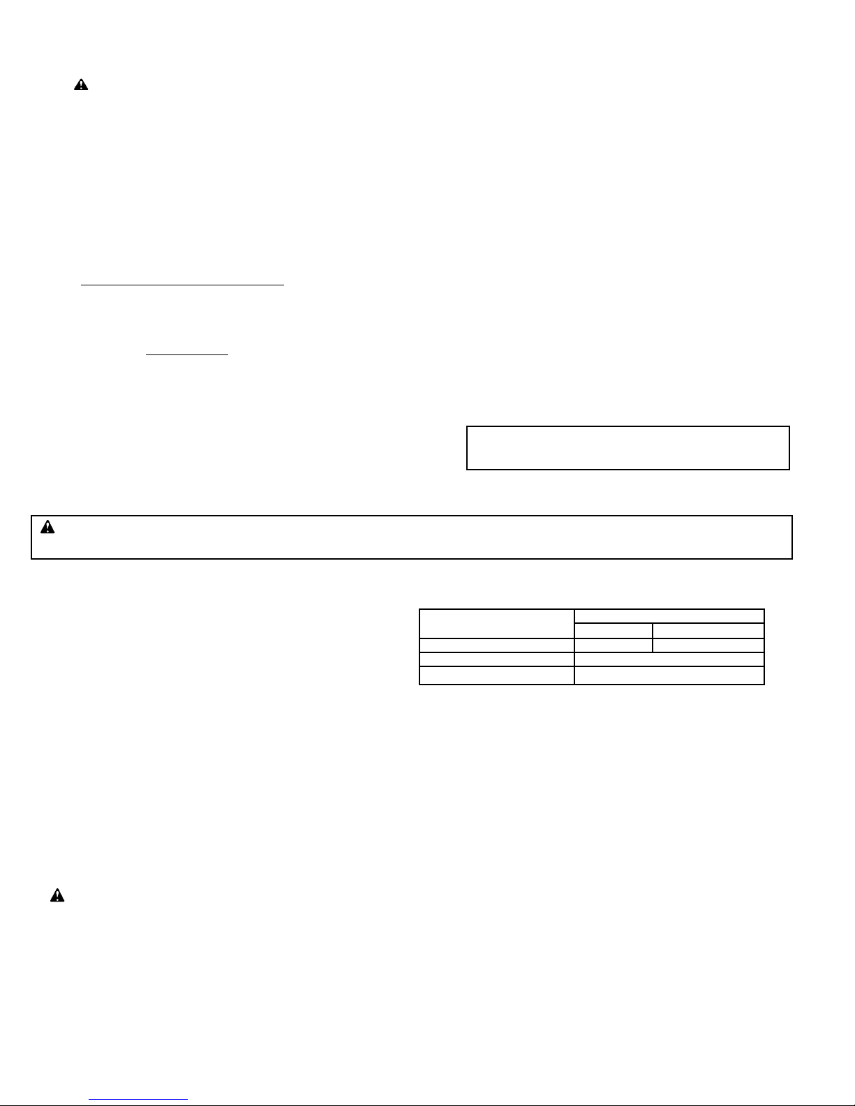
outlet pressure of 3.5" W.C. must be installed in the pilot gas
line and the pilot adjustment screw set full open.
Nominal BTU /Cu. ft. Value
NAT-1000 PROPANE-2500
Orifice Diameter .032 .025
Pilot Flame Gas Pressure
3.0"-4.0" W.C.
Approx. Capacity 2400 BTU/Hr.
TABLE 4 Pilot Specifications
X BLOWER ASSEMBLY
Cleaning of the blower wheel is usually the only service
required. Need for cleaning is indicated if the inlet screen or
blower wheel shows an accumulation of dust and lint, or if the
character of the flame indicates a deficiency of air. Motor
cooling air vents if present, should also be cleaned at this time.
■ If the motor must be replaced: Disconnect motor leads,
remove inlet ring and screen, blower wheel and the three
motor mount retainer clips. Pull motor out of keyhole brackets.
Remount in reverse order noting that brass flanges of rubber
motor mounts are located against motor. The wheel should be
located 1/4 inch inside the edge of the inlet side of the blower
housing.
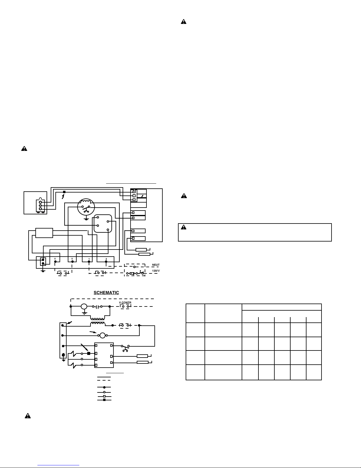
XI COMBINATION GAS VALVE
The 24 volt combination valve serves four functions: 1) Main
Manual Gas Shut-Off, 2) Manifold gas pressure regulation, 3)
Automatic electric pilot gas valve, and 4) Automatic electric
redundant main gas valve. A pilot adjustment screw and filter
are also included.
■ The pilot adjustment screw is located on the combination
valve. Remove plug for access and turn clockwise to
reduce flow.
■ The main gas pressure regulator, which has an outlet
pressure setting range of 2.0 " to 4.0 " W.C. is factory set for a
IX DRAWER ASSEMBLY
When the pilot flame gas pressure is in the proper range (see
Table 4), lint, dust, or corrosion is the most common cause of
pilot problems.
■ The retention plate and pilot are part of the drawer
assembly which can be removed as a unit. Remove the four
back plate screws; then, disconnect the pipe union, pilot tube
and control wires and pull out the drawer assembly.
■ When servicing, clean the retention plate ports and pilot
assembly including the pilot spud and electrode porcelain on
sensor rod and/or spark electrode. Examine the sensor rod. If
there is any serious corrosion or loss of metal at the tip replace
the sensor rod.
■ Make sure that the pilot mica peepsight is not damaged or
missing as air leakage through the peepsight hole could mimic
some of the conditions described below. See Figure 7.
■ Check that the pilot orifice diameter is correct.
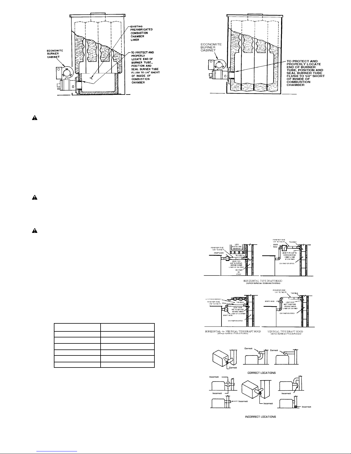
■ Make sure that the burner tube is properly positioned in the
combustion chamber entry. It must be set flush to 1/4" short of
the inside of the combustion chamber as shown in Figure 2 or
3. It must not protrude into the combustion chamber.
■ If cleaning does not eliminate the lighting problem, further
checks are required:
CAUTION: Do not indiscriminately increase pilot
orifice diameter. Pilot troubles are rarely cured in this
manner and new troubles may be introduced by causing
the pilot flame to float and lose contact with the sensor
rod.
■ If the standby gas pressure is over 14.0" W.C., or less than
4.0" W.C., refer to Section VI.
■ If the standby gas pressure is between 4.0" W.C. and 14.0"
W.C. and does not vary more than 1.0" W.C., use the pilot
adjustment screw in the combination valve (Section XI) to set
the pilot flame gas pressure at 4.0" W.C.
■ If the inlet pressure varies more than 1.0" W.C., a 1/8 inch
Maxitrol RV12 series(or equal) pressure regulator set for an

manifold gas pressure of 2.0" W.C. If pressure adjustment is
required for setting capacity, remove regulator cap for access
to slotted adjustment screw. Turning of adjustment screw
counterclockwise reduces pressure; clockwise increases
pressure. Do not adjust past point where no change in
pressure is noted.
NOTE: Pressure setting must be made with burner running
and main gas ON.
CAUTION: If gas supply pressure is below its
specified range during regulator adjustment, an overfire
condition could result when pressure returns to normal,
particularly if the regulator adjustment screw is bottomed
out.
ALWAYS confirm that at least the minimum rated gas pressure
is being supplied to the burner during regulator adjustments,
and NEVER bottom out regulator screw.
■ The tap for manifold gas pressure measurement is located
in the Burner Inlet Block (see Figure 7 or 8). Remove plug for
access.
■ If the gas pressure regulator fails to maintain a constant
manifold gas pressure within + 0.1" W.C., and it is confirmed
that the inlet gas pressure to the combination valve is 14.0"
W.C. maximum during standby, and 4.0" W.C. minimum with
the main flame on, the regulator portion of the valve is
defective and entire valve must be replaced.
■ If, on a call for heat, the main flame ignition does not occur
even though the pilot is burning, failure of the electric main
valve operator may be indicated. Refer to the trouble chart for
further information.
WARNING: If PROPANE gas is used and the burner is located in a basement, crawl space or confining space, contact your gas
supplier about installing a GAS LEAK warning device. PROPANE gas is heavier than air and can settle in low areas or confined spaces.
This would create a danger of explosion or fire. If you suspect a gas leak, follow instructions on front cover of this manual.
CONSUMER INSTRUCTIONS
MAINTENANCE
■ Keep the area around the burner clear and free of combustible
materials, gasoline or other flammable liquids or vapors. Do not
obstruct burner air openings or ventilation grilles for combustion air.
■ The motor features permanently lubricated ball bearings and
requires no routine oiling maintenance.
IMPORTANT: Check the burner flame periodically. A proper
NATURAL gas flame will appear blue at the burner face with orange
and yellow tips. A proper PROPANE gas flame will appear blue at the
burner face with yellow tips. If the flame is too rich, it will appear billowy
and yellow with hazy tips. If too lean, it will appear short and all blue.
If the flame does not appear proper, CONTACT A QUALIFIED
SERVICE TECHNICIAN FOR CLEANING AND/OR READJUSTMENT.
WARNING: If any flame is observed when the burner
is on standby, or if the ignition spark or valve operator is
heard to come on before the motor reaches operating
speed, immediately turn off the manual gas control and
burner power. A dangerous condition has developed and
must be corrected. CONTACT A QUALIFIED SERVICE
TECHNICIAN FOR READJUSTMENT OR REPAIR
.
SET OPERATING CONTROL TO OFF OR THERMOSTAT BELOW
ROOM TEMPERATURE.
TURN MANUAL GAS COCK KNOB ON COMBINATION VALVE TO ON.
TURN BURNER POWER ON.
SET OPERATING CONTROL TO ON OR THERMOSTAT TO CALL FOR
HEAT.IF THE PILOT FLAME IS NOT PROVEN WITHIN 90 SECONDS,
OR IF THE PROOF OF FLAME IS LOST DURING BURNER RUN AND
THE PILOT IS NOT RE-ESTABLISHED WITHIN 90 SECONDS, THE
CONTROL WILL SHUT OFF COMBINATION VALVE AND LOCK OUT.
TO RESET FOR RESTART, DE-ENERGIZE THE CONTROL BY
SETTING THE OPERATING CONTROL TO OFF OR THERMOSTAT
BELOW ROOM TEMPERATURE FOR AT LEAST 60 SECONDS.
REPEAT STEP 4 FOR RESTART.
TO SHUT OFF
TURN MANUAL GAS COCK KNOB ON COMBINATION VALVE TO OFF.
TURN BURNER POWER OFF.
SHOULD OVERHEATING OF THE GAS UTILIZATION EQUIPMENT
OCCUR:
-7-
LIGHTING INSTRUCTIONS
FIGURE 8 Drawer Assembly
1.
2.
3.
4.
5.
6.
1.
2.
1.
2.
CAUTION: If the combination valve has been moved
or replaced, soap bubble test for leaks with the burner
running.
■ If leakage through the valve occurs, as evidenced by
presence of pilot and/or main flame on standby, the entire
valve must be replaced.
XII ELECTRONIC CONTROL SYSTEM
The Electronic Control is a solid state device that automatically
ignites and monitors the pilot flame. It has an integral high
voltage transformer and upon a call for heat, applies high
voltage to the spark electrode and 24 volts to the pilot valve.
When the pilot flame is established and proven, the control
powers the main automatic valve.
■ If the pilot flame is not proven within 90 seconds, or if the
proof of flame is lost during the burner run and the pilot is not
re-established within 90 seconds, the control will shut off the
combination valve and lock out. To reset the control for
restart, de-energize the control by setting the operating control
to OFF or thermostat below room temperature for at least 60
seconds.
■ If the Electronic Control is changed, the replacement must
be identical to the make and model number, or must be an
authorized substitute.
WARNING: EXPLOSION HAZARD. CAN CAUSE
SERIOUS INJURY OR DEATH. THIS DEVICE CAN
MALFUNCTION IF IT GETS WET. NEVER TRY TO USE A
DEVICE THAT HAS BEEN WET - REPLACE IT.

-8-
TROUBLE CHART
Make sure the thermostat and operating controls are calling for heat. Defective wiring or loose connections can simulate the
component defects outlined below. Check associated wiring before replacing a component.
ELECTRICAL AND FLAME CHECKS MUST BE MADE IN THE ORDER LISTED.
Shut off the manual gas control to the gas utilization equipment.
Do not shut off the control switch to the pump or blower.
I. MOTOR WILL NOT RUN OR MOTOR RUNS IN
REPEATED CYCLES.
A. Confirm 120V between strip terminals 1and 2and
verify the circuit polarity and electrical ground
between strip terminal 1and burner chassis metal.
B. Check 24V* operating control circuit:
1. Between left strip terminal T and GND.
a. No voltage, transformer defective.
b. Very low voltage,* circuit is overloaded or
transformer defective.
2. Between right strip terminal T and GND.
a. No voltage, circuit between T and Tis open.
C. Confirm 120V between strip terminal 2 and motor relay
terminal 4:
1. No voltage, motor relay is defective.
2. Voltage present, motor is defective.
II. MOTOR RUNS CONTINUOUSLY, BUT NO FLAME.
A. Confirm that both Main Manual Shut-Off and
combination gas shut-off valves are in the ON
position.
B. If the pilot flame is not proven within 90 seconds, or if
the proof of flame is lost during the burner run and the
pilot is not re-established within 90 seconds, the
Electronic Control will lock out. To reset the control for
restart, de-energize the Electronic Control by setting
the operating control to OFF or thermostat below room
temperature for at least 60 seconds.
1. No pilot flame.
a. Check for 24V* between Electronic Control
terminal 24V and strip terminal GND. No
voltage, Blower Motor Interlock Switch is
defective.
C. For each of the following tests, reset the Electronic
Control per step II.B. TESTS ARE VALID ONLY
DURING THE 90 SECOND TRIAL FOR IGNITION.
1. TURN MANUAL GAS COCK KNOB OFF. Check
for 24V* between Electronic Control terminal PV
and strip terminal GND. No voltage, Electronic
Control is defective.
2. Check for 24V* between pilot valve terminal PV on the
combination valve and terminal strip GND. No
voltage, defective valve wire harness. Voltage
present, pilot valve operator is defective; replace
valve.
3. Connect manometer to pilot flame gas pressure tap.
TURN MANUAL GAS COCK KNOB ON. Separate
main valve wire at harness splice. During trial for pilot
ignition period, check gas pressure.
a. No pressure, confirm that both Main Manual
Shut-Off and combination gas shut-off valves
and pilot adjustment screw are full open.
Repeat step 3, and if still no pressure, pilot valve
operator is defective.
b. Pilot flame pressure is 3.0" to 4.0" W.C., continue
with step 4.
c. Refer to Standby Gas Pressure requirements in
Section IX and adjust or regulate the pilot gas
pressure as indicated.
4. Check for ignition spark (spark gap is approx. 5/32
±1/32) Since this is a capacitor discharge system,
observe closely when visually checking the spark as it
is faint and thread-like and may be overlooked in
bright light.
a. Between Electronic Control high voltage
terminal and strip terminal GND. No spark,
defective Electronic Control.
b. Check for ignition spark at electrode tip. No
spark, defective electrode or cable.
c. Check for gas flow at pilot tip. No flow, clogged
pilot spud or pilot tube.
III. FLAME ON ONLY DURING TRIAL FOR IGNITION
PERIOD.
A. With motor running and flame off, check line voltage
terminals for voltage as follows:
1. Between strip terminals 1 and 2- 120V; voltage
OK.
2. Between strip terminals 1 and GND - 120V; ground
OK.
3. Between strip terminals 2 and GND - "0" V; no
backfeed OK.
B. Follow reset procedure as specified in step II.B.
1. Check sensor wire for continuity.
2. Separate main valve wire at harness splice. Connect
DC microamp meter in series with sensor wire and
Electronic Control. With pilot only burning, flame
signal should not be less than 2 microamps. Adjust
pilot flame gas pressure per Section IX to obtain
acceptable signal and note gas pressure and
resultant signal for future reference.
3. Reconnect separated main valve wire at harness.
After main flame comes on, flame signal should
increase. If signal does not increase, a rich flame is
indicated. Refer to Table 3 for approximate air shutter
and/or manifold gas pressure settings (see step VI).
C. IMPORTANT: If changes are made in the main
spud orifice size, manifold gas pressure or primary air
adjustment, change the installation data tag
accordingly.
IV. PILOT FLAME ON BUT NO MAIN FLAME.
A. Check for 24V* between Electronic Control terminal
MV and strip terminal GND. No voltage, Electronic
Control is defective.
B. Check for 24V* between main valve terminal MV on
combination valve and strip terminal GND. No voltage,
defective valve wire harness. Voltage present, main gas
valve operator is defective.
V. SHORT FLAME.
A. Low gas pressure.
B. Primary air adjustment open too far.
C. Main spud orifice too small.
VI. LONG HAZY FLAME.
A. High gas pressure.
B. Primary air adjustment closed too far.
C. Dirty blower wheel.
D. Main spud orifice too large.
VII. GAS FAILS TO SHUT OFF.
A. Defective combination valve.
* Normal low voltage: Burner in standby - 24V min.
Burner running (main gas valve
energized) - 21V min.
Table of contents
Popular Indoor Fireplace manuals by other brands

HOLZMANN MASCHINEN
HOLZMANN MASCHINEN HKD15 user manual

Lennox
Lennox MONTECITO ESTATE MONTEST Installation and operation instructions

United States Stove Company
United States Stove Company VF30I user manual

Kinder
Kinder KRTC00MN Installation and maintenance instructions

Escea
Escea DL850 Installation and service guide

Majestic
Majestic QUARTZ Series installation manual