Ecoplus SWBC-3.0H-A/P Service manual

AIR SOURCE HEAT PUMP WATER HEATER
Installation & Instruction Manual
English Version

Ⅰ
Ⅱ-----------------------------------------------------------------------2
Ⅲ.Work principle------------------------------------------------------------------------------3
Ⅳ.Performance Data--------------------------------------------------------------------------3
Ⅴ.Dimension------------------------------------------------------------------------------------4
Ⅵ.Operation introductions------------------------------------------------------------------5
Ⅶ.-----------------------------------------------17
Ⅷ.---------------------------------------------------18
Ⅸ.---------------------------------------------------------------21
.To our customers(before installation)
.Product Introducing
-------------------------------------------------1
Electric Circuit Wiring Diagram
Installation instructions-------------
Maintenance-----------------
CONTENTS
Water heater
Contents

Dear Sir:
Ⅰ.To our customers Water heater
In order to use this machine safely, please read this INTRUCTION MANUAL carefully
before using and installation. Heat pump water heater is a professional machine, it may
cause damage or hazard when wrong installed, it should be installed by a competent
person in accordance with the relevant standards for the country of use.
WARNING:
ELECTRICAL POWER MUST BE SWITCHED OFF
BEFORE STARTING ANY WORK ON JUNCTION BOXES
1.Before installing the heat pump, please ensure that the electrical supply corresponds
to the specification indicated on the unit s rating label before proceeding with the
connection in accordance with the wiring diagram supplied. Please check carefully
on the rating label and the wiring diagrams that pasted on each heat pump unit.
2.The unit must be EARTHED to avoid any risks caused by insulation defects. It is
forbidden to start any work on the electrical components without switching off the
electrical supply to the unit. Electric leakage switch protection device MUST be
installed.
3.It is forbidden to start any work on the electrical components if water or high
humidity is present on the installation site.
4.When the unit is being connected, ensure that no impurities are introduced into the
pipe work and the water circuits.
5.All maintenance or repairmen of the heat pump must be performed by competent
technicians.
6.It could be hurtful when generated hot water reaches 52 ℃, please mix with cold
water before using.
7. To prevent any damage to the fan or any accidents, it is forbidden to put your
fingers or any other objects into the air outlet. Kids or children should be kept
away from the heat pump.
8. This appliance is not intended for use by persons (including children) with
reduced physical, sensory or mental capabilities, or lack of experience and
knowledge, unless they have been given supervision or instruction concerning
use of the appliance by a person responsible for their safety.
9.Children should be supervised to ensure that they do not play with the appliance.
1

Product Introduction
Safe and Reliable
heat by electricity , it use less electricity to move heat from one place to another , electric
circuit is separated from water circuit ,which is also not easy for electric shock,
inflammable , explosion and poisoning ! Safer and more reliable!
Highly efficient & Energy saving
Heat pump water heater absorb plenty of heat from free ambient air, and can supply same
hot water volume as electric heater. Electricity consumption is only 1/4 compared to
electric heater, very energy saving!
Environmental Friendly
Heat pump not only use less electricity to get heat from ambient air , but are also able to
combine using with solar equipment , will not cause pollution and no poison gas
exhausting .
All Round The Year Hot Water
Heat pump water heaters are not affected by seasonal climate, provide hot water all year
round even in cloudy or rainy days!
Durable and long-lasting time
Heat pump spare parts such as compressor and 4-way-valve are made by famous brand
manufacturer , and casing panel is corrosion resistance, very durable and long-lasting
time .
Convenient Installation
Installation site for heat pump can be the roof, the garage , the kitchen, the storing room ,
the basement and so on, very convenient on installation .
Wide Application
Heat pump water heaters are applicable for family, factory, school, hotel , hospital , and
laundry ,etc. Wide application for different using request.
Unlike traditional electric water heater, heat pump water heater do not directly generate
Ⅱ.Product Introduction Water heater
2
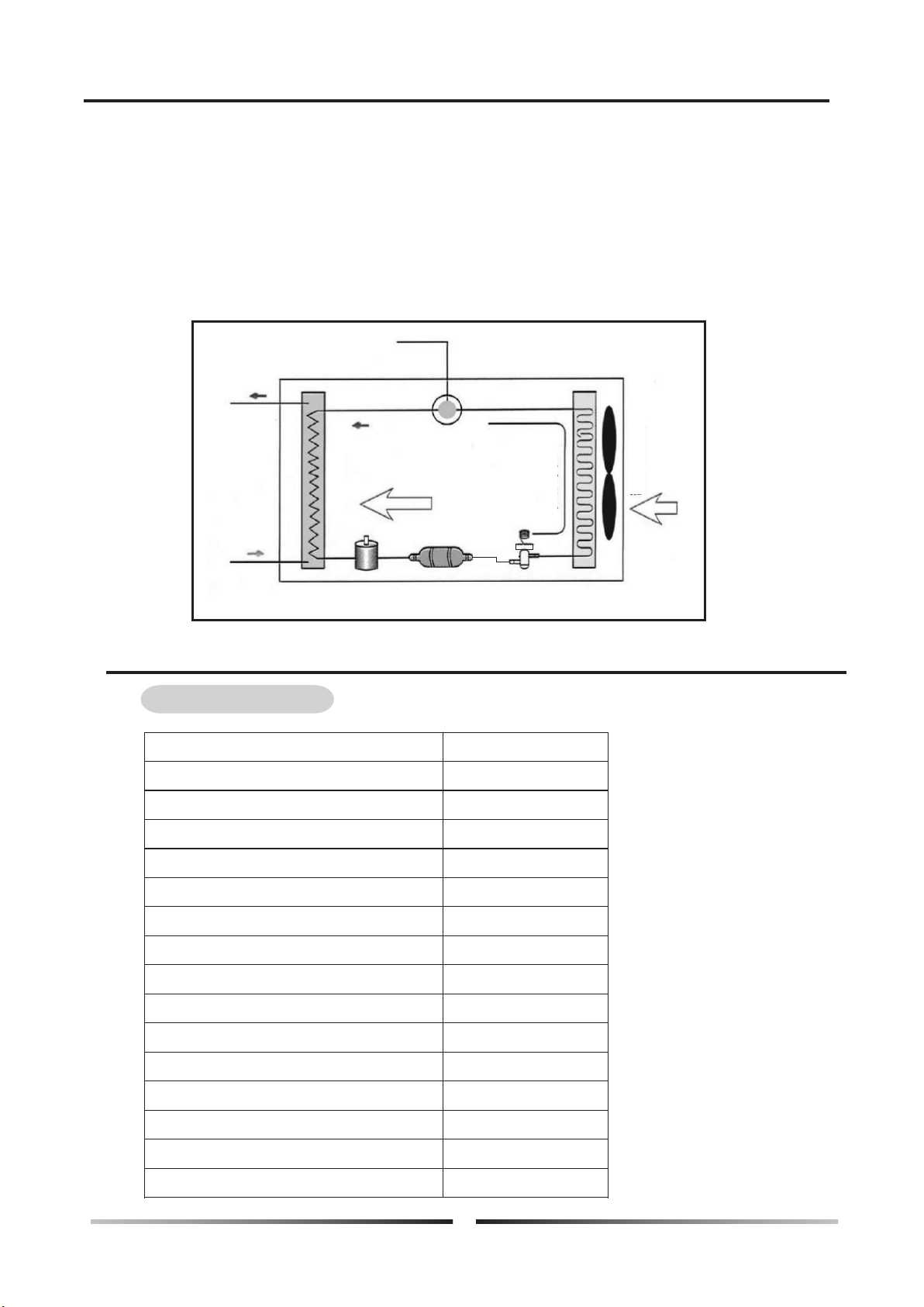
The low temperature and low pressure refrigerant gas come from the evaporate to the compressor,
After the compressor compress it , the refrigerant gas became high temperature and high pressure.
Then the gas come into the water condensation into liquid, emit a lot of condensation heat,
condensing heat absorbed by water, making the water temperature increased, and then the liquid
refrigerant come through the expansion valve, with a fan , the evaporate heat in the air, after all
evaporation , the low pressure compressor refrigerant gas inhalation in the compressor, after working
through the compressor, a high temperature and high pressure of the refrigerant gas from the
compressor to exhaust emissions, such reciprocating cycle.
Power supply
Hot water
outlet
Water inlet
Compressor
Heat energy
pass to water
Dis c harg e
he a t equ i pment
Absorbing
air heat
energy
Ab so rbin g
heat eq uipmen t
Liquid tank Dry filter Expansion valve
Ⅲ.Work principle Water heater
Performance Data
Ⅳ.Performance Data Water heater
3
SWBC-3.0H-A/P
Model
Rated heating capacity(w)
Power supply(V/Ph/Hz)
Input power(kw)
Running current(A)
Circulating unit hot water generated(L/h)
Thermostat factory setting( )℃
Thermostat maximum setting( )℃
Water connections
Compressor quantity
Fan motor quantity
Fan motor input(w)
Water Flow Volume(m /h)
3
Noise[dB(A)]
Net dimension(mm)
Net weight(kg)
3000
220/1/50
0.81
3.8
514
55
60
G3/4"
1
1
30
0.44
49
635*530*447
48

The dimension for air source heat pump water heater
Ⅴ.Dimension Water heater
4

5
Ⅵ.Operation introduction Water heater
Operation introduction
1. Controller introduction
ON/OFF MODE UP/DOWN
SET TIMER
Heating mode
Data showing area
Timer on
Timer off
Clock
Timer on/ off sign
defrosting
button
---to turn on or turn off your heat pump. Long press 10 seconds for factory
default setting.
and button
-----up and down button to check or change setting.
Press these two button at the same time for 3seconds, lock the keyboard.
button
—Change setting. While use or button to check parameter, press
button at the moment, could change the setting of current parameter. After
finished, press to confirm.
Press button alone, could come to clock setting. First set the hour data,
and use or button to change the hour data.
Secondly press again, to come to minute data setting. Still use or
button to change the minuted data. After that, press to confirm.
button
----Press for 3 seconds in standby status, could enter for Force Defrost.
button
----Button for timming.Integrating with up and down button, to set the time
for turning on or turning off the heat pump.
2 Wire controller button definition

3 Wire Controller Operation
In the state of OFF, LCD display clock and working mode only. see P1
When Press “power” button, heat pump turn on, and LCD display as below.
Parameter data setting
You could check and change the setting from any status as below steps.
1.Press up/ down button for the parameter you want to change setting.
2.Press button once, and the right data flash
3.Use up/down button to change the setting.
Press button again for confirm.
Ⅵ.Operation introduction Water heater
6

Real Time Clock Setting
In the default state,press " " once to enter Real Time
Clock Setting State; In the state of Real Time Clock
Setting, press" " once again,hour numbers flash, press
" "or " ",can adjust the hour for the clock.
After the clock hour is setted, press " " once again,
minute numbers flash, press " "or " ",can adjust
the minute for the clock. After setting the clock minute,
press " " again to confirm the clock setting and return
default state.
Timming ON /OFF Setting
In default state, press " " once to enter Timing Setting state.press " " again,
the hour numbers for timming ON flash, press " " or " " to adjust the hour for
timming ON setting.
After setting the hour for timing ON, press " " once again, the minute number
for timming ON flash, press " " or" " to adjust the minute for timming ON.
After setting the minute for timming ON, press " " once again,to enter the
hour setting of timming OFF;
After setting the timming OFF hour and minute, press " "again,to confirm
current setting and return to default state.
In the state of Timming Setting, press " " once,it will clear timming ON /OFF
setting and return to default state.
Keyboard Lock & Unlock
In default state, long press " " and " " for
3 seconds AT THE SAME TIME ,vibrator "bee"
once , the keyboard will be locked.
In the state of Locked, long press " " and " "
for 3seconds,vibrator "bee" for once, the
keyboard will be unlocked.
Timming ON Timming OFF
Back Up Memory After Power Resumption
When the heat pump is working in normal state and electricity power cut off
suddently, the system will run in the last setting record after power resumption.
Ⅵ.Operation introduction Water heater
7

0- 1
-F(-15 -
F(15℃)
℃)
0
Can adjust
Can adjust
Temperature difference between gas suction
and evaporator tube
10- 5 0 35 Can adjust
Can adjust
Manually control steps for electronic expansion
valve
-15~10℃
0~99℃
0~99℃
-35~80℃
-35~80℃
-35~80℃
0~125℃
-35~80℃
0~125℃
-35~80℃
10- 47
Tested data
Tested data
Tested data
Tested data
Tested data
Tested data
Tested data
Tested data
Tested data
Tested data
E heater start temp
Inlet water temperature
Outlet water temperature
Evaporator tube temperature of system 1
Gas suction side temperature of system 2
Evaporator tube temperature of system 2
Gas suction side temperature of system 1
Ambient temperature
Exhaust temp of system 1
Exhaust temp of system 2
Actual steps for electronic expansion valve
3. Parameters
1- 1 2M i n
40 M in
-7℃
13℃
5℃
55℃
35℃
0℃
5℃
8M i n
30 - 90 M in
Can adjust
Temperature to enter to defrosting in heating
mode -30 -0℃℃
Can adjust
Temperature to exit defrosting under heating
mode
50℃
Remark
Range
Definition
Tank water temperature setting 25- 60℃ Can adjust
Default
Parameters
2- 3 0℃
2- 15℃
45-60℃
20-40℃
Can adjust
Defrosting time
Can adjust
Can adjust
Can adjust
Can adjust
EEV control (manual or auto)
1 / 2
0 manual,
1 auto
2
1
Can adjust
System quantity
Temp difference
Second set point (maximum)
Second set point (minimum)
Can adjust
Defrosting Cycle
Water pump controlling mode:
0: water pump always on
1: water pump shut off after compressor stops
for 30s.
8
SET 1
SET 2
SET 3
SET 4
SET 5
SET 6
SET 7
SET 8
SET 9
SET A
SET B
SET C
SET D
SET E
1
2
3
4
5
6
7
8
9
A
Operation introduction
0Can adjust
SET 0
0:protect on
1:protect off
Ambient temperature too low protection
parameter
Ⅵ.Operation introduction Water heater

Operation introduction
4 Failure code and parameter tables
Protect/Failure
Heat ump in Stand-by mode
Normal running
Inlet water temperature sensor failure
Outlet water temperature sensor failure
Coil temperature sensor 1 failure
Gas suction side temperature sensor 1 failure
Ambient temperature sensor failure
Coil temperature sensor 2 failure
Winter anti-freezing protection I
Winter anti-freezing protection II
Gas suction side temperature sensor 2 failure
Exhaust temp sensor 1 failure
Exhaust temp sensor 2 failure
Exhaust 1 high temp protection
Exhaust 2 high temp protection
System high pressure protection
System low pressure protection
Water flow switch failure
Power source wrong/open phase
Wire controller communication failure
Defrosting
PP1
PP2
PP3
PP4
PP5
PP6
PP7
PP7
PP8
PP9
PP10
PP 11
PP 12
EE1
EE2
EE3
EE4
EE8
Defrost
Long-distance
controller Remark
Ⅵ.Operation introduction Water heater
9

5) Two ways to connect wifi
Install the APP of “SmartLink3 Demo”
Turn on the heat pump, and make sure the area of heat pump installed cover with wifi signal.
What's more, make sure your smart phone with wifi connected.
Long press the timer button of LCD controller for 5 seconds. See below pic.
Then input the password for example 12345678 of WIFI TP LINK-22233.
(The wifi should be your local wifi, and your password of local wifi)
And press “Start”, see below pic. (Your smart phone should near the controller to ensure
easy connected for wifi)
Timer button
◎
◎
◎
◎
a. First way
For Android System
Ⅵ.Operation introduction Water heater
10
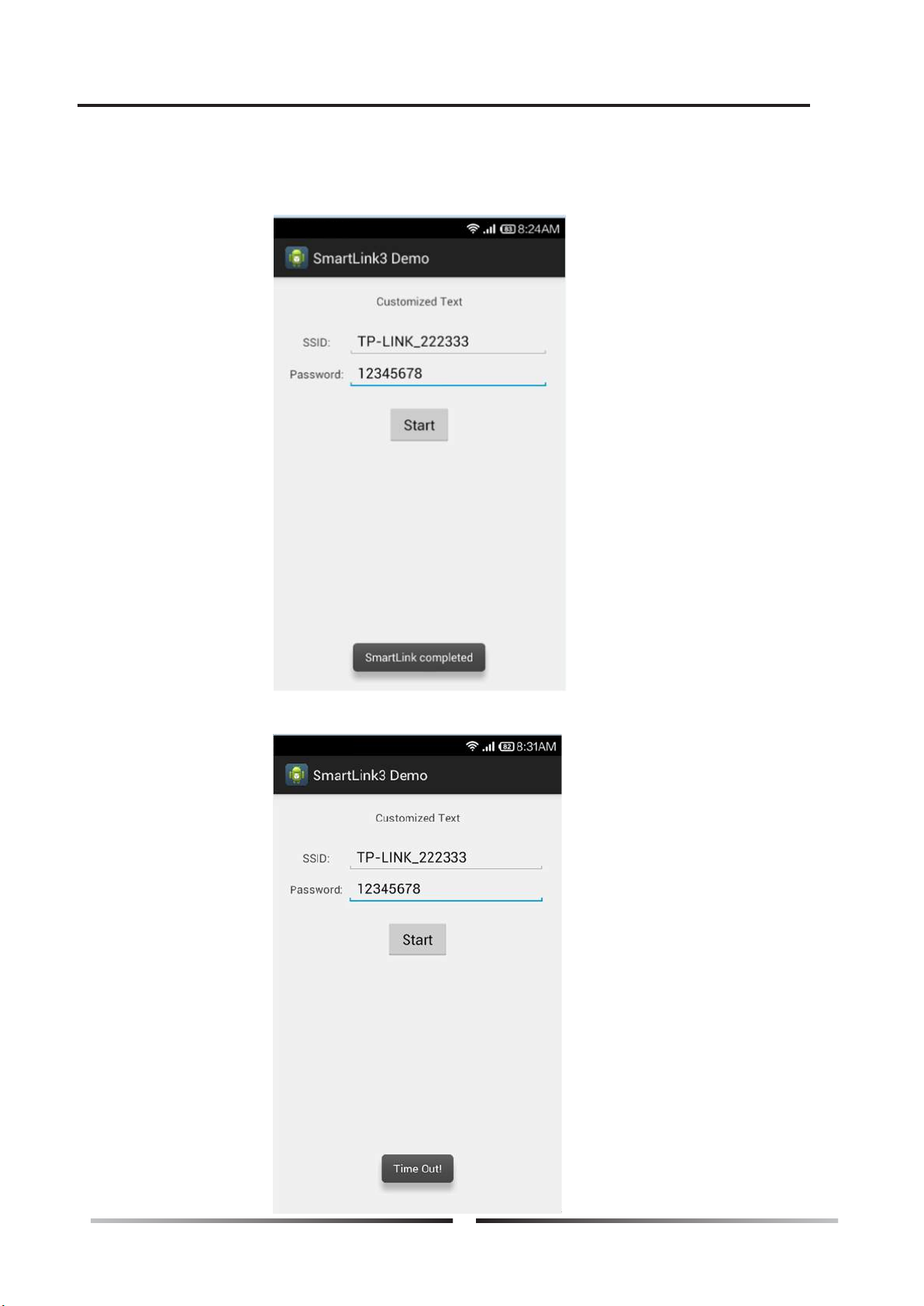
It may take 1 minute to match all wifi setting.
If connected successful, it could show “SmartLink Compelted” as below pic.
If failed, it could show “time out”as below pic, then you have to repeat step 3 & 4 again.
◎
◎
a. First way
Ⅵ.Operation introduction Water heater
11

◎
◎
◎
a. First way
Find out “SmartLink” in the APP Store, download and install it.
You can scan below QR code for fast installation as well.
Input the passwords of your local wifi.
Other setting please refer to Android system, as they are the same.
Remarks, initial wifi setting may need a few times to complete. Please try more times if once
is not successful.
For IOS System
12
Ⅵ.Operation introduction Water heater
b. Second way for wifi setting
◎
◎
◎
◎
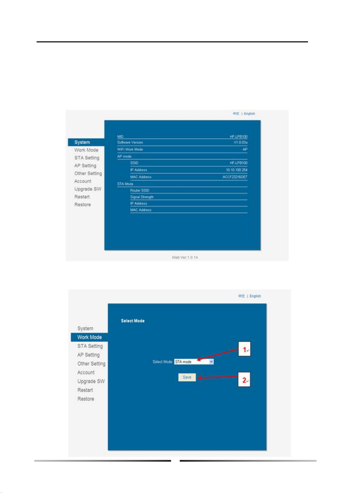
Turn on the heat pump.
Use laptop or smart phone to find wifi “HF-LPB100”and connect it.
Open website of “10.10.100.254”, input user name and password as below.
User name: admin Password: admin
After that, you could find below interface.
Select work mode, change to STA mode. And then press Save.
See below ref pic.
13
Ⅵ.Operation introduction Water heater
Ⅵ.Operation introduction Water heater
b. Second way for wifi setting
◎
◎
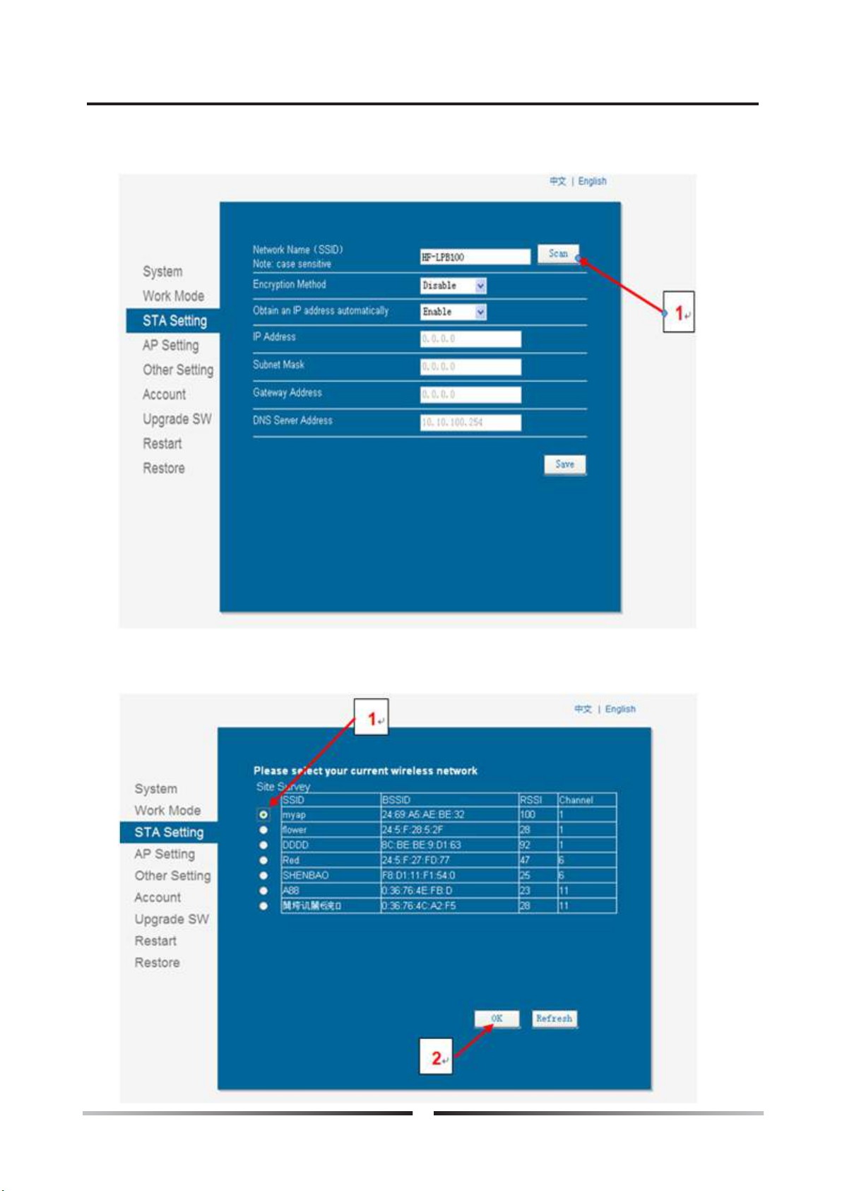
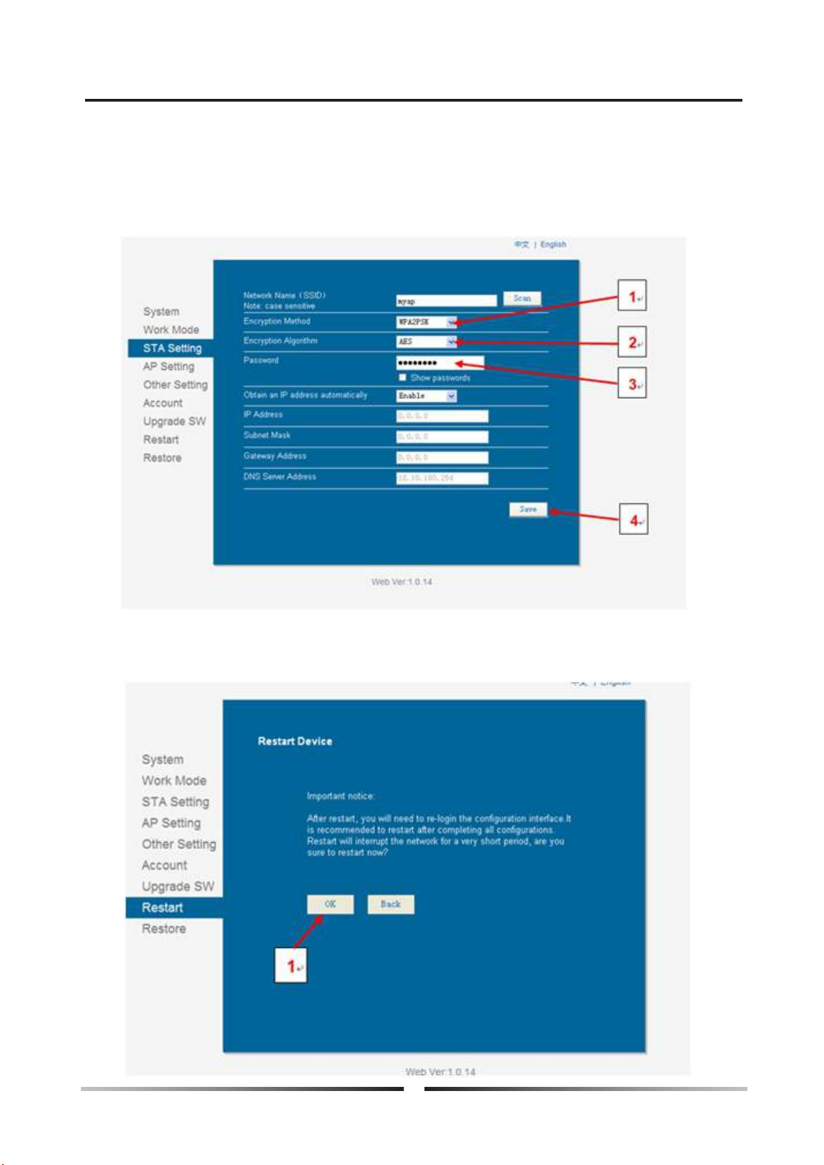
Then select STA setting, press Scan, then press Save. See below refer pic.
Please choose the safety and reliable local area network which available. Then press OK to
Confirm.
14
Ⅵ.Operation introduction Water heater
b. Second way for wifi setting
◎Make sure the Encryption Method choose WPA2PSK, and Encryption Algorithm choose AES.
Input the password of your local area network. Then press Save.
After finished all above steps, come to Restart interface, and press OK to confirm
RESTART. See below pic.
◎
15

c. Remarks
Make sure to press “SAVE” for each setting.
If IP address changed, all above setting need to re-set.
If you try first way of “Smartlink3 DOMO” and failed,
then try the second way for wifi setting.
Have to long press Turn on/off button (see below pic)
for 10 seconds, otherwise, wifi signal will never come
out.
After wifi connected successful, you could have inquire about heat pump status by below
website. http://app.xlink.cn:9001/query.html
Or you could scan below QR Code to enter the website for Heat pump status checking.
Fast inquire (only to check 1 or 2 heat pump units)
Agent research (Able to check all the heat pumps as order). Or visit below website.
http://app.xlink.cn:9001/login.html
◎
◎
◎
◎
◎
d. Fast Inquiry
Turn on/off button
Ⅵ.Operation introduction Water heater
16
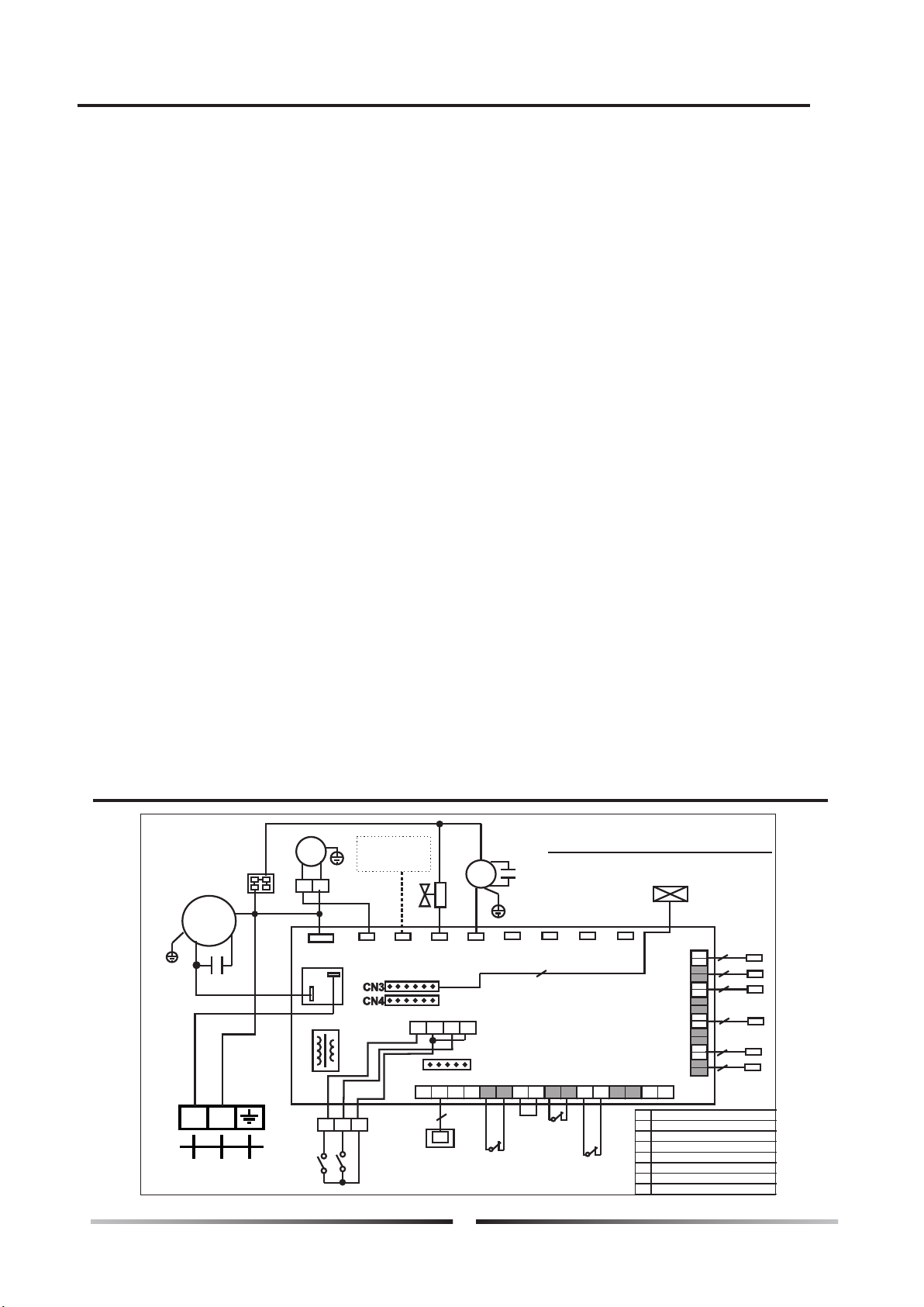
Ⅶ.Electric Circuit Wiring Diagram
17
6 Setting about S1 & S2 switch
S2 Switch----Long distance demand
6.1 Second Set Point available when S1 switch has well connected.
At the same time, water temp set point setting decided by ambient temp, Parameter
SET 9 and Parameter SET A. (Both SET 9 & SET A Parameter would be adjusted)
o
Parameter SET 9 (maximum setting range 45~60 C)
o
Parameter SET A (minimum setting range 20~40 C)
o
A. When ambient temp < 5 C, set point temp refer to the data of Parameter SET 9
o
B. When ambient temp >15 C, set point temp refer to the data of Parameter SET A
o o
C. When 5 C ≤ ambient temp ≤ 15 C, Set point temp = Data of Parameter SET 9-
(Data of parameter SET 9- data of parameter of SET A)/(15-5)*(Ambient temp -5 )
For example, when ambient temp is 18 deg c, Parameter SET 9 data is 50 deg c,
Parameter SET A data is 20 deg c.Then set point temp =50-(50-20)/(15-5)*(18-5)
S1 Switch---Second Set Point
6.2 When S1 disconnected, set point temp control by LCD controller. (Refer to the
setting of Parameter 40 (default setting 50 deg c).
6.3 Heat pump will turn on when S2 switch has well connected.However, S2 well
connected, and suddenly press the off button on the LCD controller.Heat pump
will stop for 3 minutes. After 3 minutes heat pump continue to turn on if S2 Still
has been connected.
6.4 The timer function is out of validity when S2 switch is connected.
6.5 Heat pump turns off when S2 switch is disconnected. Meanwhile, need to use
LCD controller to switch on/off the heat pump.
2
2
2
2
2
2
4
5
AC-N
4-way
Valve
Transformer
CN7
OUT3
OUT2 OUT4 OUT5 OUT6 OUT7 OUT8 OUT9
NO
COM
T5
T4
T3
T6
T2
T1
SEN5
SEN7
SEN6
SEN8
SEN4
SEN3
SEN2
SEN1
+12V CND B- A+ PORT5 PORT4 PORT3 PORT2 PORT1 SEN9
High
Pressure
Switch
Low
Pressure
Switch
Wire
controller
FM
Water
flow
WIRING DIAGRAM
PORT6 PORT7
1 2
From POWER SOURCE
CM
R
C
S
Compressor
L N
Electronic
Expansion Valve
Water pump
PM
Ⅵ.Operation introduction Water heater
S1
3 4 5
S2
T1
T2
T3
T4
T5
T6
S1 Second set point
S2 Long distance demand for heating
Water inlet temp sensor
Water outlet temp sensor
Exhaust temp sensor
Coil temp sensor
Ambient temp sensor
Air Circulation Temp Sensor
To Ac
contactor
of E-heater

Installation instructions
1. Unit installation
1).Installation location
Host unit
1Should be installed in a larger & well-ventilated place.
1Installation location should ensure unhindered access outlet (inlet & outlet shown as below).
1Install gutter or set up positions near the outfall, to facilitate the drainage.
1The installation base or bracket should be steady,
to ensure the smooth operation of running units.
1Make sure the unit is vertical after installation,
and no incline.
1Make sure not to install the host unit in the any
conditioner of pollution, corrosive gases, sun
and fallen leaves, etc.
1Installation location must not next to place of
incendive, easy-explosion and fire .
1Installation must pay attention to the distance
between the barriers shown in below picture
(pay attention to arrow direction).
1The air inlet and outlet can connect the φ150 air duct for air ventilation, see below pic.
Water tank
1Water tanks should be placed where ambient temperature is above 0℃ .
1Can be installed outdoors or the top of the building (based on the size of water tanks and
the load-bearing capacity of the building and so on).
1Do not install water tanks in the pollution, corrosive gases place.
2).Unit installation
1Units base can be installed as cement concrete structures, steel brackets can also be used,
add the shockproof rubber pads , make the base surface flat.
1Units can be designed based on the working performance.
(See Table of technical performance parameters)
1Unit should have drain or drainage inlets.
1Normally required to install in the place where setted cement concrete base.
Above 1000mm
1000mm above the top
Air inlet
Air outlet
Heat pump
Heat pump Heat pump Heat pump
Air inlet
Air inlet
Above 1000mm
Ⅷ.Installation instructions Water heater
≥ mm1000
Outside Wall
≥ mm1000
≥ mm1000
18
Table of contents
Other Ecoplus Water Heater manuals


Popular Water Heater manuals by other brands


Rheem
Rheem 22DV40S-36N Specifications

Dometic
Dometic WH-6GEA user manual

Fakir
Fakir OLYMPUS THERMO instruction manual

Maytag
Maytag HRX75CQRSCGA user guide

STIEBEL ELTRON
STIEBEL ELTRON DHB 18 STi Operating and installation

Excelsior
Excelsior GAS-FIRED WATER HEATER Installation & operating instruction manual