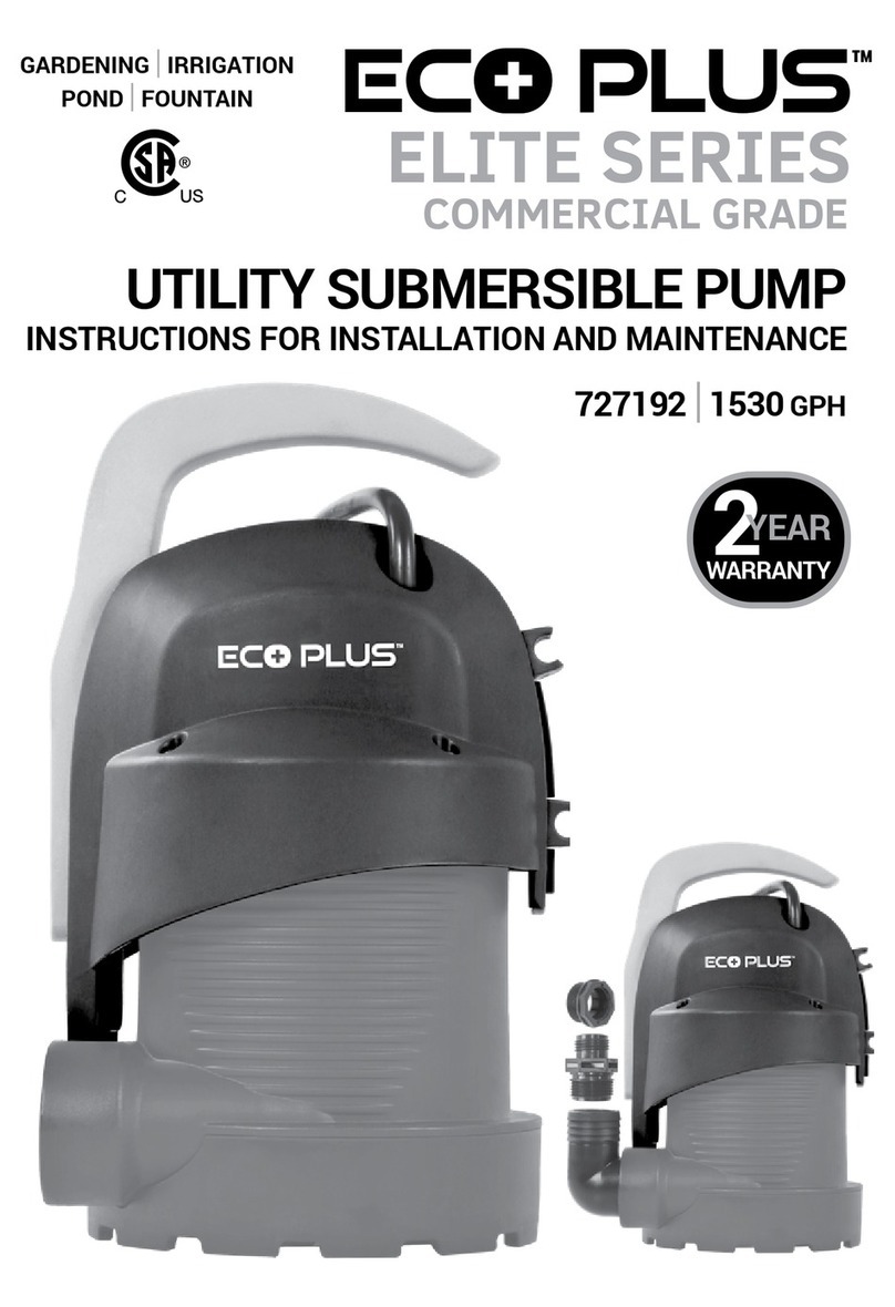
Ecoplus 727184 Operating and maintenance manual

AUTOMATIC SUBMERSIBLE PUMP
INSTRUCTIONS FOR INSTALLATION AND MAINTENANCE
ELITE SERIES
COMMERCIAL GRADE
GARDENING
|
IRRIGATION
POND
|
FOUNTAIN
727184
|
1746 GPH
727186
|
3168 GPH
WARRANTY
2
YEAR

2
INDEX
1. APPLICATION...........................................................................................................2
2. PUMPABLE LIQUIDS ................................................................................................3
3. TECHNICAL SPECIFICATIONS..................................................................................3
4. FITTINGS AND DIMENSIONS ...................................................................................4
5. PERFORMANCE CURVE AND FLOW RATES..............................................................5
6. MANAGEMENT AND INSTALLATION ........................................................................6
7. START-UP.................................................................................................................7
8. PRECAUTIONS .........................................................................................................7
9. MAINTENANCE AND CLEANING...............................................................................8
10. TROUBLESHOOTING................................................................................................9
11. LIMITED WARRANTY..............................................................................................10
12. PLANNING AND NOTES ...................................................................................11-12
WARNING: Read entire instruction manual carefully before using.
REMOVE THE POWER PLUG FROM THE ELECTRICAL SOCKET BEFORE HANDLING THE
PUMP TO AVOID ELECTRIC SHOCK.
The pump must always be activated when it is immersed in water. If all of the water is
evacuated, the pump must be deactivated immediately by removing the plug from the
electrical socket. ABSOLUTELY AVOID DRY OPERATION.
Do not use in swimming pools, ponds or basins where people are present.
Do not use for pumping hydrocarbons (petrol, diesel fuel, combustible oils, solvents).
Do not pump continuously for long periods of time unless in the case of emergency.
Always clean the pumps before storage. See the chapter “Maintenance and Cleaning”.

3
1. PUMPABLE LIQUIDS - Max. particle size Ø.20 inch.
The pump is watertight and must be immersed in liquid.
2. TECHNICAL SPECIFICATIONS
• Supply voltage: 115 – 120V, see electrical data plate
• Delayed line fuses (115 – 120V version): indicative values (Ampere)
• Storage temperature: 14º F – 104º F
Fresh water ●
Rainwater ●
Clear waste water ●
Dirty water ❍
Waste water containing solid particles with long bers ❍
Fountain water ●
River or lake water ●
● Suitable
❍ Not suitable
Hydraulic
data
Dimensions/weight
Range of use/materials
Max. pressure
Max. head
Max. working pressure
Low suction capability (AUTO)
Low suction capability (MAN)
Electrical
data
Power
Voltage
Frequency
Amps
Flow rate max.
Max. particle size
Pump dimensions
See illustration
Liquid range temperature
Max. ambient temperature
DNA / DNM NPT
Net weight
Length of power cable
Impellers
13.2 psi |0.9 Bar
29.5 ft |9 m
87 psi |6 Bar
1.78 in |45 mm
0.08-0.12 in |2-3 mm
650 Watt
115 V-120 V AC
60 Hz
6
52.8 gpm |12000 l/h
0.2 in |5 mm
8.7 in x 7.3 in x 13 in
221 mm x 185 mm x 330 mm
32.8 ft |10 m
32°-95° F |0°-35° C
104° F |40° C
1¼ in M /1¼ in M
1
10.6 lbs |4.98 kg
TECHNICAL
SPECIFICATIONS 1746 GPH
|
⅕HP 3168 GPH
|
¼HP
Product# 727184 Product# 727186
8.7 psi |0.6 Bar
19.7 ft |6 m
87 psi |6 Bar
1.78 in |45 mm
0.08-0.12 in |2-3 mm
275 Watt
115 V-120 V AC
60 Hz
2.6
29.1 gpm |6600 l/h
0.2 in |5 mm
8.7 in x 7.3 in x 13 in
221 mm x 185 mm x 330 mm
32.8 ft |10 m
32°-95° F |0°-35° C
104° F |40° C
1¼ in M /1¼in M
1
10.6 lbs |4.98 kg

4
7.3 in
8.7 in
13 in
FITTINGS AND DIMENSIONS
Integrated
check valve
Multiple tting
options
1 in NPT
1 in barbed
1½ in barbed
1½ in NPT

5
PERFORMANCE CURVE
0
2
20
4
6
8
10
12
Q (l/min)
H (m)
H ()
40 60 80 100 120 140 160 180 200
0
8
16
24
32
40
Q (gpm)
0 4 8 12 16 20 24 28 32 36 40 44 48 52
7
2
7
1
8
4
-
1
7
4
6
G
P
H
7
2
7
1
8
6
-
3
1
6
8
G
P
H
Low suction
capability
Very low suction
capability down to
1/16 in (45 mm).
16.4 ft
|
5 m max. 6.9 gpm
26 l/min
727184
9.9 ft
|
3 m max. 19.5 gpm
74 l/min
3.3 ft
|
1 m max. 26.4 gpm
100 l/min
16.4 ft
|
5 m max. 38.3 gpm
145 l/min
727186
9.9 ft
|
3 m max. 47.5 gpm
180 l/min
3.3 ft
|
1 m max. 52.8 gpm
200 l/min
Flow rate max.
29.1 gpm
|
6600 l/h
Flow rate max.
29.1 gpm
|
6600 l/h
Max. head
19.1 ft
|
6 m
Max. head
29.5 ft
|
9 m

6
THE PUMP MUST BE SUPPORTED BY A BASE. NEVER SUSPEND THE PUMP FROM PIPES.
3. MANAGEMENT
3.1 Storage: Pump must be stored in a dry, dust free covered area that is free from
vibrations. Keep the pump in its original packaging until time of installation.
3.2 Transport: Avoid subjecting the pump to needless impacts and collisions.
4. WARNINGS
Do not carry pump by the power cable. Always carry pump using the handle.
• Never allow the pump to run dry.
• The sealing device contains a non-toxic lubricant which may alter the characteristics of pure
water in the unlikely event of leaks.
5. INSTALLATION
The electrical system must be compliant with local codes.
Screw on the elbow with hose-tail tting provided. Use a
pipe tightening clamp to secure the pipe to the tting.
• If the bottom of the trap where the pump is to be placed
is particularly dirty, a raised support should be provided
so as to avoid blocking of the suction grid (Fig.1)
• Totally immerse the pump in the water.
• Ensure that the minimum dimensions of the trap in
which it is housed are as follows:
Min. base dimensions 7.87”x7.87” (200x200 mm)
Min. height 15.75” (400 mm)
• The dimensions of the trap must always be in relation
to the quantity of water arriving and to the flow of the
pump, so as not to subject the motor to excessive
starts/hour. It is strongly recommended not to
exceed 20 starts/hour.
ALWAYS INSTALL THE PUMP IN VERTICAL POSITION.
6. ELECTRICAL CONNECTION
The length of the power cable limits the maximum depth of pump immersion.
Follow the indications on the technical data plate and technical specications on page 3.
(Fig.1)

7
7. START-UP
1) Insert the plug of the power cable in a 115 – 120V power socket.
2) When the float reaches the ON level, the pump will start and will continue operating
until it reaches the OFF level.
Automatic operation (A):
3) The integrated float switch starts and stops the pump automatically when the
indicator (2) is positioned on “A”.
Manual operation (M):
4) To start the pump, lift the knob (3) position indicator (2) on “M”. In these conditions the
suction level of the pump will be down to 0.08”-0.12” ( 2-3 mm).
5) In order to check the performance and/or clean the float switch, open the cover (1)
position the knob (3) to “O”.
Automatic operation (A)
Manual operation (M)
8. PRECAUTIONS
RISK OF FREEZING: when the pump remains inactive at a temperature lower than 32º F, it
is necessary to ensure that there is no water residue which could freeze causing cracks in the
plastic parts. If the pump has been used with substances that tend to form deposits, or with
water containing chlorine, rinse after use with a powerful water jet in order to avoid the
formation of deposits or coatings which would reduce the performance of the pump.

8
9. MAINTENANCE AND CLEANING
In normal operation the pump does not require any type of maintenance. In any case, all repair
and maintenance work must be carried out only after having disconnected the pump from the
power supply. When restarting the pump, ensure that the suction lter is always tted so as
not to create the risk or possibility of accidental contact with moving parts.
9.1 Cleaning the suction grid
(Fig. 2)
• Switch off electric power to the pump (a).
• Drain the pump.
• Unscrew the screws on the lter (b).
• Remove the suction grid (c).
• Clean and reassemble the suction grid.
9.2 Cleaning the impeller
(Fig. 3)
• Switch off electric power to the pump (a).
• Drain the pump.
• Unscrew the screws on the lter (b).
• Remove the suction grid (c).
• Wash the pump with clean water to remove
possible impurities between the motor and
the pump jacket (d).
• Clean the impeller (d).
• Check that the impeller can turn freely.
• Reassemble parts in inverse order
of disassembly.
9.3 Cleaning and testing of integrated float
(Fig. 4)
• Switch off electric power to the pump (a).
• Drain the pump.
• Push the switch lever and disassemble the cover of the float (b).
• Remove the float, check if anything prevents
free flow and proceed with cleaning (c).
• Reassemble parts in inverse order
of disassembly.
(Fig. 2)
(Fig. 3)
(Fig. 4)
a
a
a b c
b
b
d
c
c

9
10.TROUBLESHOOTING
DISCONNECT THE PUMP FROM THE POWER SUPPLY BEFORE TROUBLESHOOTING.
If there is any damage to the power cable or pump, necessary repairs or replacements must be
performed by the manufacturer, authorized dealer, or by an equally-qualied party in order to
prevent any risks.
ISSUE POSSIBLE CAUSES REMEDIES
The motor does
not start or
make any noise.
A. Check if voltage is reaching motor.
B. Check the protection fuses.
C. Switch is not activated by the float.
A. Check if plug is inserted correctly.
B. If burnt out, change them.
C. Increase the depth of the trap.
The pump does
not deliver flow.
A. Suction grid or hose are blocked.
B. The impeller is worn or blocked.
C. The head required is higher than
the pump’s performance.
D. Presence of air.
E. Water level is lower than the
suction minimum.
A. Remove the obstructions or
straighten the hose if it is twisted.
B. Replace the impeller or remove
the obstruction.
C. Replace pump with a pump with
a higher head.
D. Wait at least 1 minute until it
is eliminated.
The pump does
not stop.
A. The float is not deactivating
the switch.
A. Check that the float to see if it
moves freely.
The flow rate is
insufcient.
A. Check suction grid for blockage.
B. Check the impeller and the delivery
pipe for blockage or encrusted.
C. Ensure the check valve is not
partially blocked.
A. Remove any obstructions.
B. Accurately clean the check valve.
The pump stops
after running for
a short time.
A. The thermal overload protection
device stops the pump.
A. Check that the fluid being pumped
is not too dense.
B. Check that the water temperature
is not too high.
C. Make sure there is no solid
particles blocking the impeller.
D. Make sure power supply complies
with the technical specications.

10
When purchased from an authorized Hawthorne dealer, this product is covered by a LIMITED
WARRANTY available at hawthornegc.com/warranties. You can also obtain the Terms of Sale
and Limited Warranty by calling Hawthorne toll free at 1-888-478-6544 or writing Hawthorne at:
Hawthorne Hydroponics LLC, 3204 NW 38th Circle, Vancouver, WA 98660, Attn: Customer Service.
PRODUCT WARRANTY SCHEDULE
PRODUCT WARRANTY PERIOD
727184 - 1746 GPH 2 year limited warranty
727186 - 3168 GPH 2 year limited warranty
LIMITED WARRANTY

11
PLANNING GRID

Manufactured for Hawthorne Hydroponics LLC, a subsidiary of The Hawthorne
Gardening Company
|
3204 NW 38th Circle, Vancouver, WA 98660
|
©2018
HawthorneGC.com
|
Canada: HawthorneGC.ca
NOTES
121918LM
This manual suits for next models
2
Table of contents
Other Ecoplus Water Pump manuals
Popular Water Pump manuals by other brands

PVR
PVR EU 160 Operating and maintenance instructions

Everbilt
Everbilt THD1075 Use and care guide

Crane
Crane DEMING 4507 Series Installation, operation & maintenance manual

Grundfos
Grundfos Hydro Multi-B Installation and operating instructions
Powerhorse
Powerhorse 750124 owner's manual

Grundfos
Grundfos CRK Series Installation and operating instructions