2/29
NT 1004-H00 10 16 SLS24 i - SLS36 i e
ECCENTRIC PISTON PUMP
MOUVEX PRINCIPLE
SAFETY INSTRUCTIONS, STORAGE, INSTALLATION AND MAINTENANCE
SLS24 i - SLS36 i MODELS
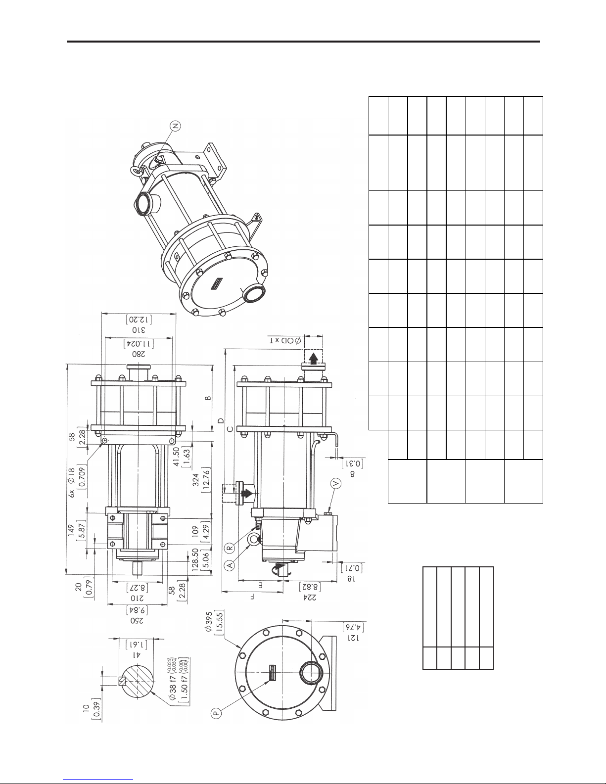
TECHNICAL CHARACTERISTICS
- Maximum pump speed : 460 rpm
- Running temperatures :
• ambient .........................................................-15°C →+ 40°C
• continuous pomped product .........................-15°C →+100°C
• washing / rinsing / sterilisation product......... 0°C →+121°C
• heating fluid (jacket) .....................................-15°C →+180°C
- Maximum suction pressure :
• In normal use, the suction pressure must be higher than the required
NPSH and less than 2 barg (29 psig).
• During CIP/SIP of the pump, the suction pressure must not exceed
3 barg (43,5 psig).
• Pump stopped, the pressure must not exceed 6 barg (87 psig).
- Acceptable maximal differential pressure :
• SLS24 i . . . . .9 bar (130,5 psi)*
• SLS36 i . . . . .6 bar (87 psi)*
- Maximum pressure jacket : 5 barg (72,50 psig)
- Cylinder capacity :
• SLS24 i . . . . .0,946 litre
• SLS36 i . . . . .1,420 litre
* When the pump works with an inlet gauge pressure less than zero, the
maximum outlet pressure will be calculated as if the inlet pressure is
equal to zero.
USED PRESSURE UNITS
Unit without suffix :
Differential pressure, for example, pressure difference between
equipment suction and discharge.
Unit with suffix "a" :
Absolute pressure.
Unit with suffix "g" :
Gauge pressure, given regarding to atmospheric pressure
(~101325 Pa, taken at 1 bar / 14,5 psi in this IOM).
Psuc Pdis
Pump
Example :
Psuc = -0,2 barg = 0,8 bara
Pdis = 8,8 barg = 9,8 bara
∆P= Pdis - Psuc = 9 bar
TABLE OF CONTENTS Page
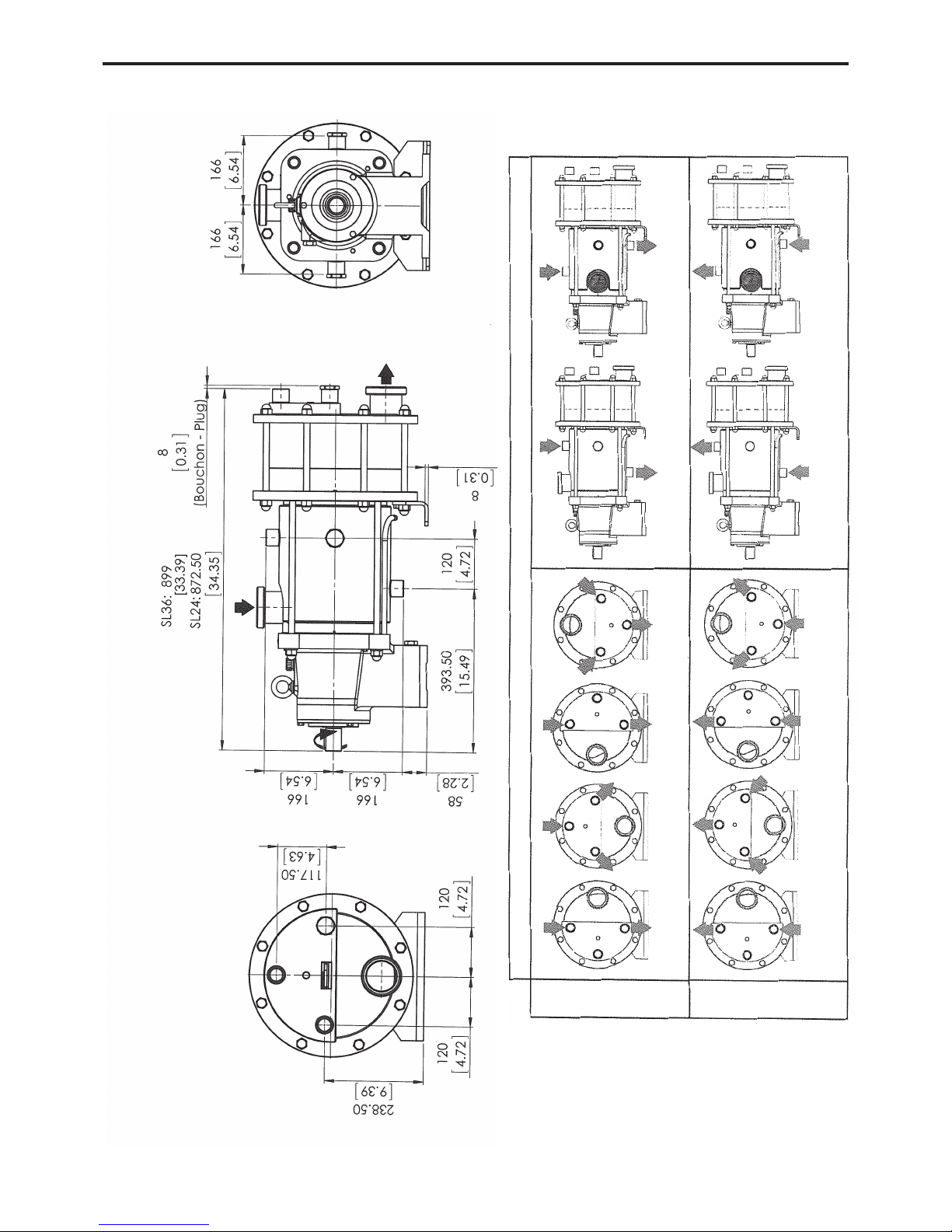
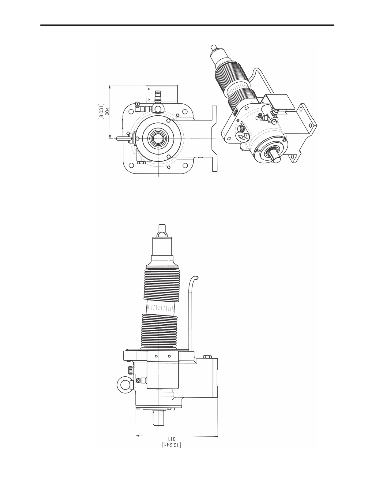
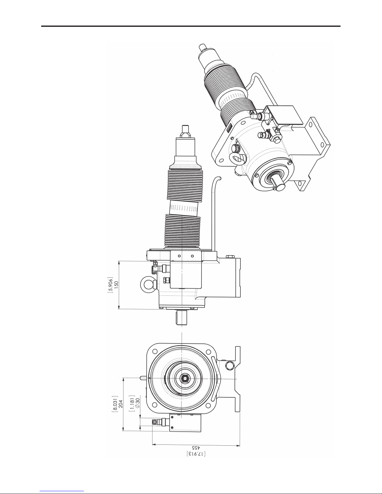
1. OVERALL DIMENSIONS . . . . . . . . . . . . . . . . . . . . . . . . . .3
2. INSTALLATION . . . . . . . . . . . . . . . . . . . . . . . . . . . . . . . . .8
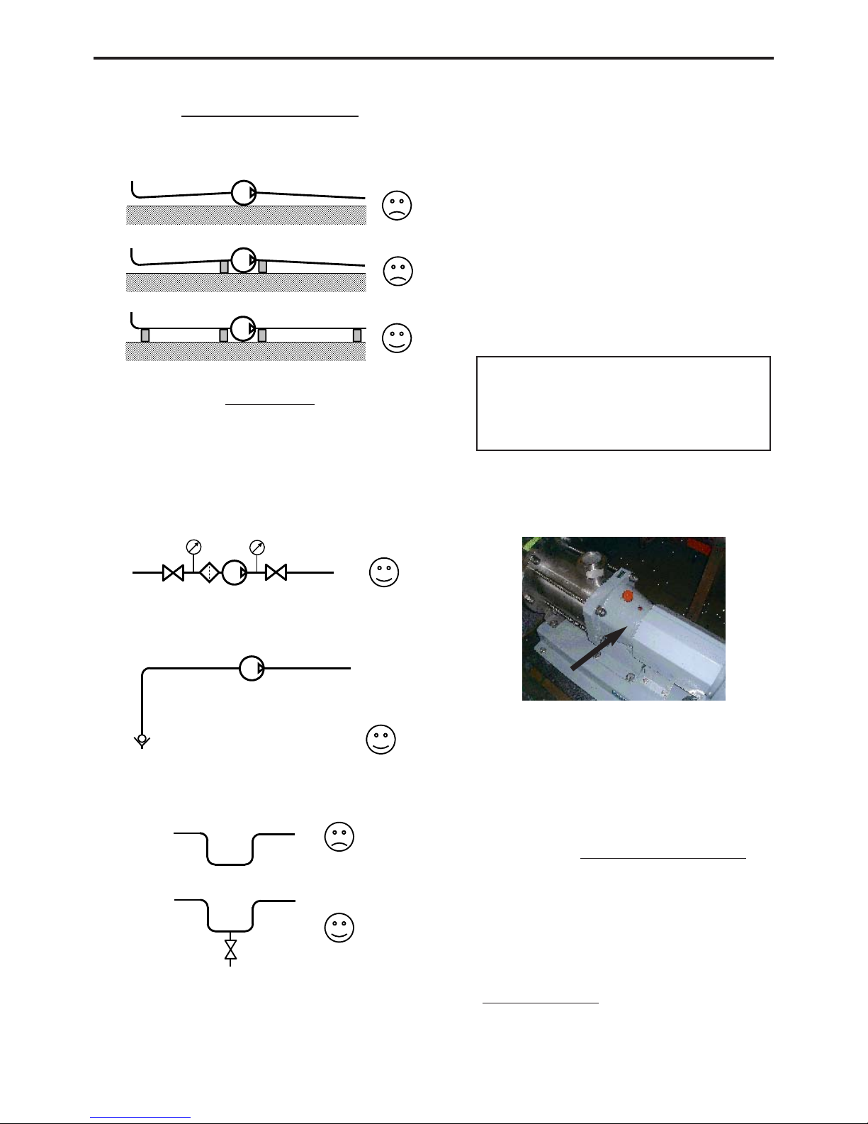
2.1 Installation design . . . . . . . . . . . . . . . . . . . . . . . . . . . . .8
2.2 Orientation of the pump ports . . . . . . . . . . . . . . . . . . . .9
2.3 Direction of rotation . . . . . . . . . . . . . . . . . . . . . . . . . . . .9
2.4 Protection of the pump installation . . . . . . . . . . . . . . . .9
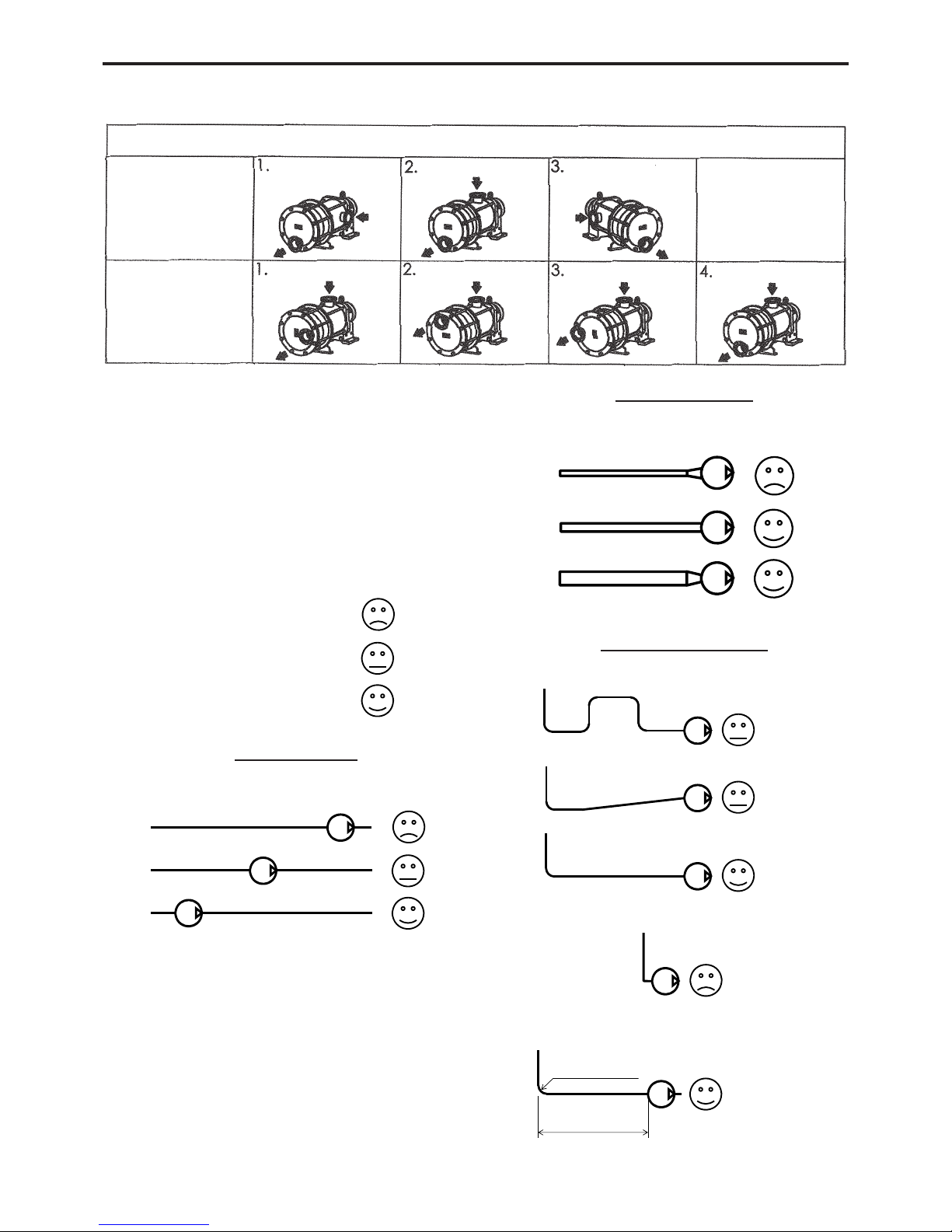
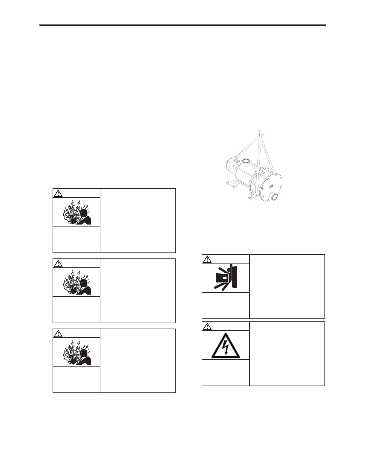
2.5 Hoisting devices . . . . . . . . . . . . . . . . . . . . . . . . . . . . .10
2.6 Unit Assembly . . . . . . . . . . . . . . . . . . . . . . . . . . . . . . .10
3. UTILISATION . . . . . . . . . . . . . . . . . . . . . . . . . . . . . . . . .13
3.1 Noise level . . . . . . . . . . . . . . . . . . . . . . . . . . . . . . . . .13
3.2 Commissioning . . . . . . . . . . . . . . . . . . . . . . . . . . . . . .13
3.3 Dry running . . . . . . . . . . . . . . . . . . . . . . . . . . . . . . . . .13
3.4 Pump stop . . . . . . . . . . . . . . . . . . . . . . . . . . . . . . . . . .13
3.5 Scrapping . . . . . . . . . . . . . . . . . . . . . . . . . . . . . . . . . .13
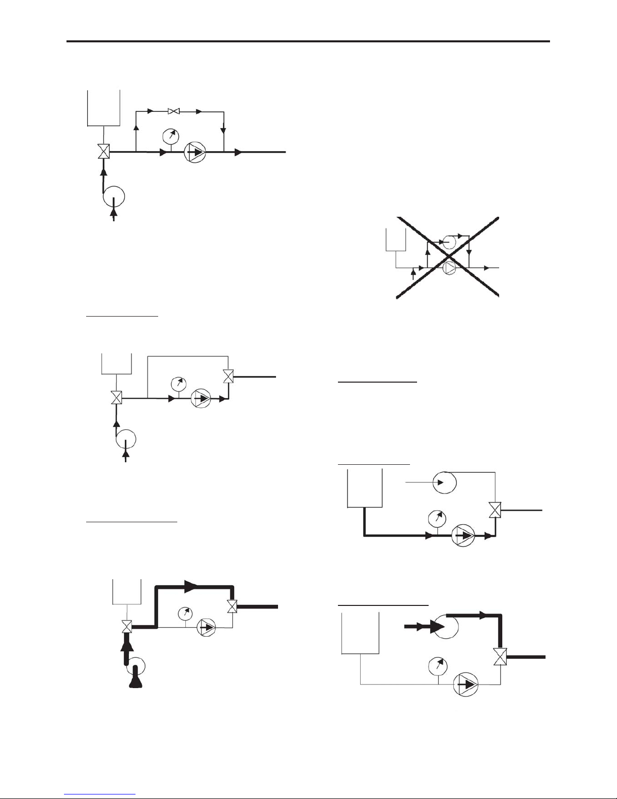
4. CLEAN IN PLACE (CIP) & STERILISATION IN PLACE
(SIP) . . . . . . . . . . . . . . . . . . . . . . . . . . . . . . . . . . . . . . . .14
4.1 General . . . . . . . . . . . . . . . . . . . . . . . . . . . . . . . . . . . .14
4.2 CIP circuit recommended . . . . . . . . . . . . . . . . . . . . . .14
4.3 Pumps arranged in series . . . . . . . . . . . . . . . . . . . . . .14
4.4 Pumps arranged in parallel . . . . . . . . . . . . . . . . . . . . .15
4.5 Successive cycles . . . . . . . . . . . . . . . . . . . . . . . . . . . .16
4.6 Sterilisation In Place (SIP) . . . . . . . . . . . . . . . . . . . . .16
5. MAINTENANCE . . . . . . . . . . . . . . . . . . . . . . . . . . . . . . . .16
5.1 Necessary tools . . . . . . . . . . . . . . . . . . . . . . . . . . . . .16
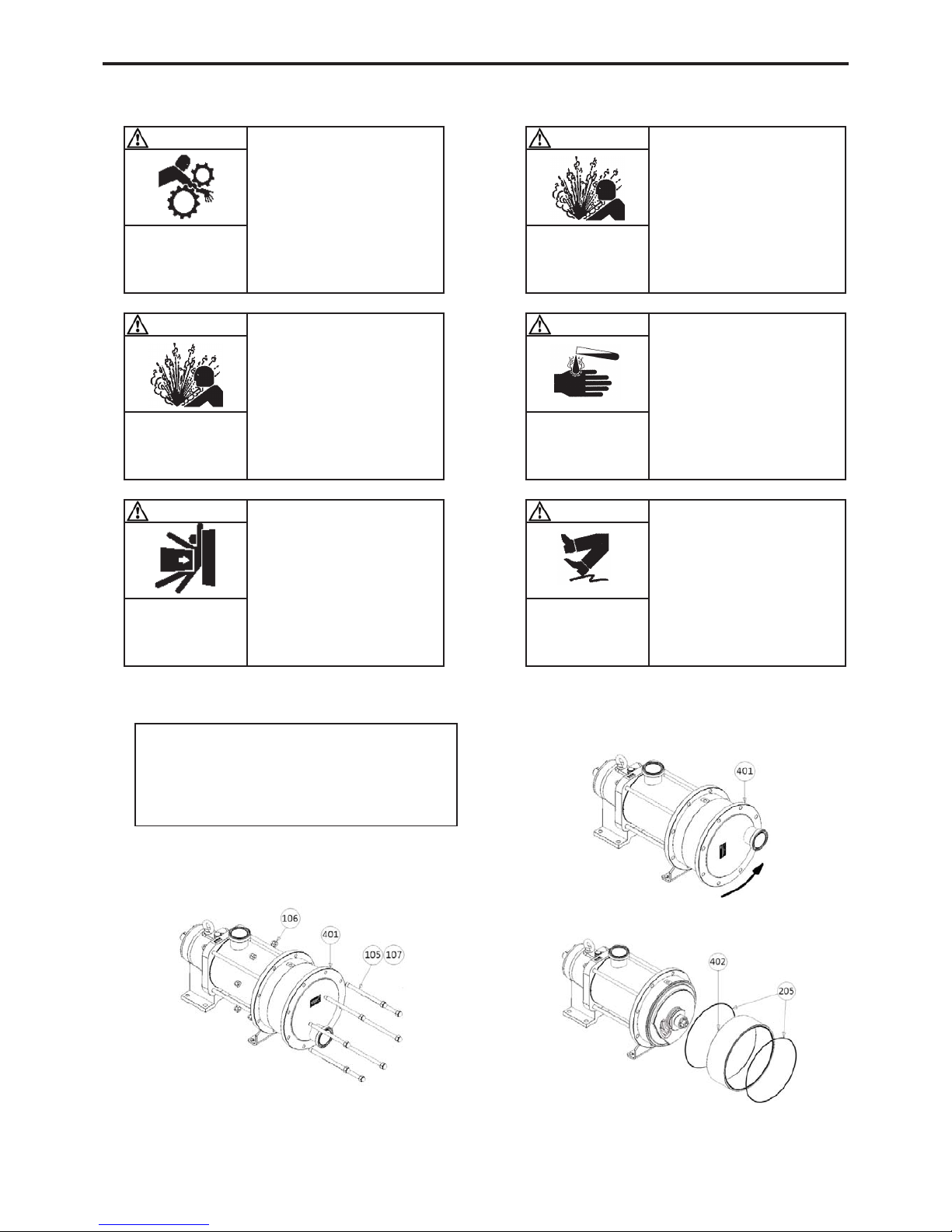
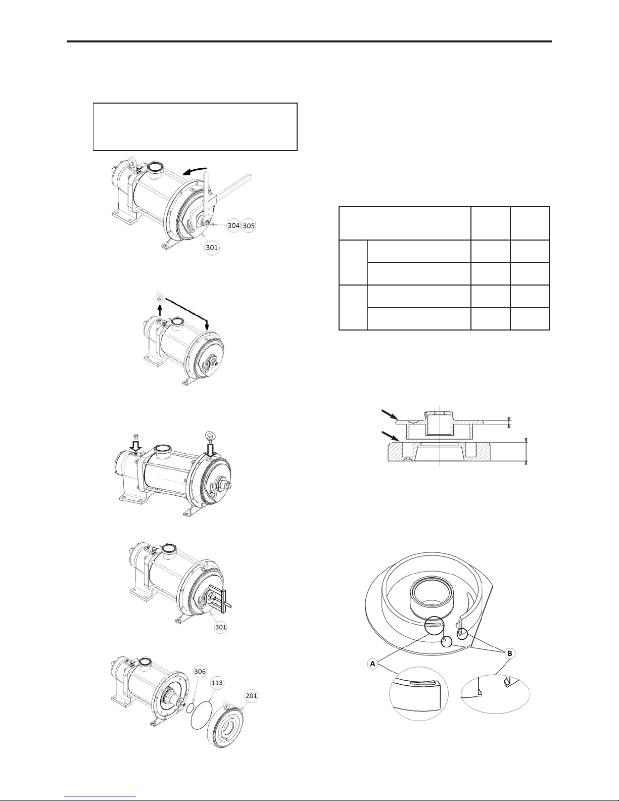
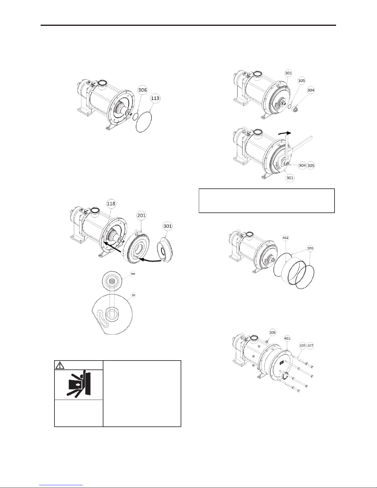
6. OPENING OF THE PUMP . . . . . . . . . . . . . . . . . . . . . . . .17
6.1 Assembly / Dismantling . . . . . . . . . . . . . . . . . . . . . . . .17
6.2 Checking of parts . . . . . . . . . . . . . . . . . . . . . . . . . . . .18
7. ASSEMBLY OF CYLINDER/PISTON . . . . . . . . . . . . . . . .20
8. PROTECTION OF THE BELLOWS . . . . . . . . . . . . . . . . . .21
9. CHANGING THE LIP SEAL . . . . . . . . . . . . . . . . . . . . . . .23
10. CHANGING THE ORIENTATION OF THE PORTS . . . . .24
10.1 Discharge port . . . . . . . . . . . . . . . . . . . . . . . . . . . . . .24
10.2 Suction port . . . . . . . . . . . . . . . . . . . . . . . . . . . . . . . .24
11. DRAINING OF BEARING . . . . . . . . . . . . . . . . . . . . . . . .25
12. OPTIONS . . . . . . . . . . . . . . . . . . . . . . . . . . . . . . . . . . .25
12.1 Bellows monitoring system . . . . . . . . . . . . . . . . . . . .25
13. STORAGE . . . . . . . . . . . . . . . . . . . . . . . . . . . . . . . . . . .26
13.1 Short duration (≤ 1 month) . . . . . . . . . . . . . . . . . . . .26
13.2 Long duration (> 1 month) . . . . . . . . . . . . . . . . . . . .26
13.3 Restarting . . . . . . . . . . . . . . . . . . . . . . . . . . . . . . . . .26
14. TROUBLESHOOTING . . . . . . . . . . . . . . . . . . . . . . . . . .27
15. CERTIFICATE OF CONFORMITY . . . . . . . . . . . . . . . . .29
Definition of safety symbols
This is a SAFETY ALERT SYMBOL.
When you see this symbol on the product, or in the manual,
look for one of the following signal words and be alert to the
potential for personal injury, death or major property damage.
Warns of hazards that WILL cause serious personal injury,
death or major property damage.
Warns of hazards that CAN cause serious personal injury,
death or major property damage.
Warns of hazards that CAN cause personal injury or property
damage.
NOTICE
Indicates special instructions which are very important and
must be followed.
DANGER
WARNING
CAUTION