Ecor Tech Advanced Driving Assistant System User manual
1
USER MANUAL
Advanced DrivingAssistant System

2
Thank you very much for choosing our products. You are kindly
recommended to carefully read the user manual prior to using this
system, which is believed to be quite helpful for correct use of this
product.
Copyright
2015, Ecor Tech Co., Ltd., Copyright reserved.
Any trademark and trademark name mentioned in this User Manual
are owned by the legally registered company.
Declaration of Responsibility
Without permission of EcorTech, this Manual must not be, in any
form or manner (electronic, electromagnetic, optical, or manual, etc.)
reproduced, transmitted, transcribed, filed or translated into other
language and computer language.
We prepare this Manual with the purpose of facilitating users to use
and understand our products.We will try our best to ensure the accuracy
of contents of this Manual, but we still cannot ensure the completeness
of contents of this Manual. Since we have been continuously updating
and upgrading our products, we reserve the right to change this Manual
at any time without notice.
Version record
Infrared thermal imaging automobile driving assistant system Dec.
04, 2015 V1.0

3
Contents
1. User Information.......................................................................5
1.1. Disclaimer .............................................................................5
1.2. Service principle....................................................................5
1.3. Precautions...........................................................................6
1.4. Daily use and maintenance...................................................6
2. Product Profile..........................................................................7
2.1. Introduction ...........................................................................7
2.2. Overview of product function.................................................7
2.3. Product appearance..............................................................8
2.4. Main characteristics...............................................................9
2.5. Alarming strategy ................................................................15
3. Technical Specifications of Product........................................20
4. Product Use ...........................................................................23
4.1. Knowledge on thermal imager system.................................23
4.2. Startup of thermal imager system........................................24
5. Troubleshooting Common Faults............................................24
5.1. Non-video image.................................................................24
5.2. “Lines” or double image shown in image.............................24
5.3. Dithering image...................................................................25

4
5.4. Dim image...........................................................................25
5.5. Repair and maintenance .....................................................25
6. Standard Accessories and Optional Accessories....................28
6.1. List of standard accessories and optional accessories ........28
Annex I: Knowledge on Infrared Technology ..............................29
1) Operating principle of infrared thermal imager........................29
2) What is an infrared thermal imaging automobile driving assistant
system?.........................................................................................29
3) Why to use an infrared thermal imaging automobile driving
assistant system?..........................................................................30
4) Vehicles to which the vehicle-mounted infrared night-vision
system is applicable ......................................................................31
Annex II: Additional Descriptions on Alarm Function....................32

5
1. User Information
1.1. Disclaimer
Before using this product, please make sure you have carefully read
and fully understood the instructions for use and this Disclaimer, and you
will install and use this product in strict accordance with this product
manual. Failure to install and use this product in strict accordance with
instructions is likely to lead great inconvenience, and even cause
property loss and personal injury. Our company will not bear any legal
responsibility for any property loss and personal injury caused by
improper installation and use of this product by the user.
Our company will not bear any legal responsibility for any mistake
and accident caused by own reasons or reasons of any third party in the
course of using this product by the user or property loss and personal
injury caused by misjudgment against images.
Any person not qualified for automobile driving is prohibited from
using this product; any person qualified for automobile driving can only
use this product on the vehicle for which he/she is qualified for
automobile driving.
1.2. Service principle
For this product series, exchange and warranty are available within
one month and one year after sale respectively. Specific service
principle is specified according to the accompanying warranty card, and
we provide the warranty service; as for products subject to suspended
production, elimination, special price, and products sold at reduced
prices, etc., the time standard shall be based on written documents of
our company such as notices.

6
1.3. Precautions
Please do not directly expose the lens of the infrared thermal
imaging automobile driving assistant system to high intensity radiation
sources such as the sun, laser, and electric welding machine.
This system combines precision optical lens and electrostatically
sensitive circuits. Please do not throw, beat it, and pay attention to
electrostatic protection to avoid damage.
Do not disassemble this system by yourself. Contact the
manufacturer in case of failure. Otherwise, we are not responsible for
warranty repair.
This system can not take the place of head light or the human visual
image formed with the help of head light. Drivers are kindly requested to
pay attention to road conditions during driving.
1.4. Daily use and maintenance
To improve and guarantee your safe driving experience to the hilt
and ensure that this system provide you with excellent driving
assistance service normally, please be sure to follow the following:
1) Prior to using this system, please confirm the system is reliably
installed. As for long-term use of this product, please regularly
check and confirm that this system is firmly installed and
without any foreign obstruction.
2) During use, please ensure that this system operates within the
specified range of voltage and operating temperature. Please
do not power on and power off the machine frequently. The
shutdown and restart interval shall be not less than 30s.

7
3) To enhance the imaging quality, surface of the ophthalmic lens
of lens of this system is coated with a layer of reflection
reducing coating. Avoid touching the surface of the lens with a
hand as acid materials on skin left by fingerprint will damage
the surfaces of the coating and lens. Please wipe the lens with
special lens cloth or glasses cloth when cleaning is required.
2. Product Profile
2.1. Introduction
In recent years, the driving assistant system has been increasingly
known by people. The driving assistant system can, without interfering in
the normal driving of drivers, improve the driving comfort and safety of
drivers.
Infrared thermal imaging automobile driving assistant system can
facilitate drivers to identify pedestrians in front of the vehicle in advance
in the dark (without the night vision assistance system, this kind of
identification would be realized quite late). The infrared night vision
driving assistant system is capable of extracting the heat generating
object which is not within the lighting vision of the vehicle yet from its
background, displaying it in the screen, which greatly improves the
driving experience of driver and the driving safety factor.
2.2. Overview of product function
Thank you for choosing our far infrared night vision driving assistant
system which is just like eyes seeing through clearly the night and
assists you in traveling freely and returning home safely.
Based on the infrared thermal imaging technology, the infrared
thermal imaging automobile driving assistant system converts the

8
thermal imaging contents within the field of view into 2D images, and
display them via the display. It can effectively eliminate strong light
stimulation from the vehicle in the opposite direction, and interference
caused by glare in the opposite on the sight, without any effect on the
field of view. It helps drivers, in the dark, and especially under such
severe weather conditions as rain, snow, fog and haze, and sand and
dust, clearly observe vehicles, pedestrians, and obstructions, etc., on
the road; thus, safety of the driver, passenger, and the third party can be
greatly improved. This system can automatically identify pedestrians
and vehicles in front of the automobile, mark the target position with a
rectangular frame in the infrared thermal image, and, at the same time,
judge the possible collision risk in a real-time manner, and give a
warning prompt to the driver.
The infrared thermal imaging automobile driving assistant system
can greatly improve the environmental perception ability of drivers,
significantly improve the driving safety factor and driving experience of
drivers, and effectively safeguard personal and property safety of
drivers.
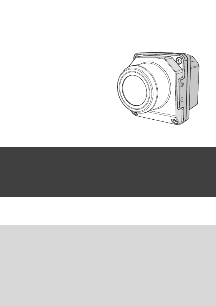
2.3. Product appearance
The infrared thermal imaging automobile driving assistant system
is as shown in Fig. 1.
9
Fig. 1 Infrared thermal imaging automobile driving assistant system
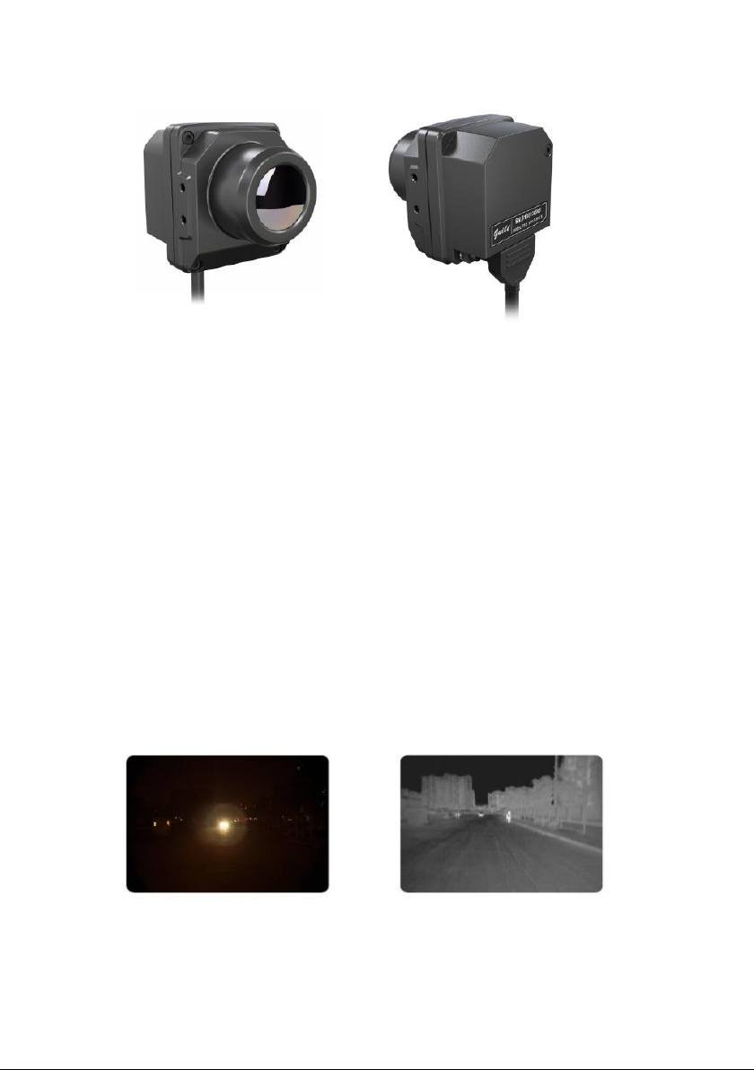
2.4. Main characteristics
· Foregrounding the non-luminous heating body:
The infrared thermal imaging automobile driving assistant system
can, under all weather conditions, automatically identify and foreground
such non-luminous heating body as the walking person, ride man,
vehicle, animal for the driver. It can help the driver better understand the
overall road conditions by displaying the road conditions beyond the
scope of the headlight light beam, effectively improve the visual effect in
case of insufficient light, as shown in Fig. 2.

10
Fig. 2 Effect in night by using the infrared thermal imaging automobile
driving assistant system
· Long detection distance:
Under the condition of good field of view, the operating distance of
the infrared thermal imaging automobile driving assistant system can be
up to 300m; under severe weather conditions (heavy rain, heavy fog,
haze, sand and dust, etc.), the operating distance of the night vision
system will be reduced to a certain extent.
For comparison, the irradiation distance of asymmetric dipped
headlight at the opposite lane side is about 60m, and that of being near
the road side is about 120m. The irradiation distance of headlight on full
beam is only 200m, which is also smaller than the operating distance of
the night vision system.
Since the operating distance of the infrared thermal imaging
automobile driving assistant system has obvious advantages as
compared to the dipped headlight and headlight on full beam, its
pre-alarm function targeted at potential risk wins the precious time for
the driver in terms of safety protection, which is very important for
avoiding traffic accidents, and safeguarding the personal and property
safety of persons in the automobile, as shown in Fig. 3.

11
Fig. 3 Effective identification distance of infrared thermal imaging
automobile driving assistant system
· Anti-dazzling function:
The infrared thermal imaging automobile driving assistant system
creates corresponding images by collecting the external infrared
radiation energy, so the headlights on full beam of the automobile in the
opposite direction cause on effect on the infrared imaging, which
effectively reduces the driving potential safety hazard caused by
dazzling of the driver, and improves the safety of driver during
automobile meeting, as shown in Fig. 4.
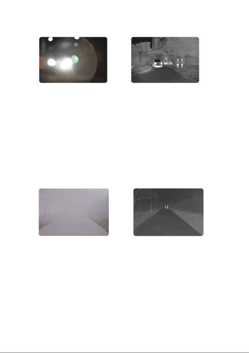
12
Fig. 4 Effect of anti-head-on dazzling by using the infrared thermal
imaging automobile driving assistant system
· All-weather use
The infrared thermal imaging automobile driving assistant system
adapts to all kinds of bad weather (rain, fog, haze, sand and dust, etc.),
and is not affected by the ray of light. It is fit for various periods of times
and various weather environment, as shown in Fig. 5.
Fig. 5 Foggy day effect by using the infrared thermal imaging
automobile driving assistant system
· Pedestrian identification function
This system not only has good identification performance against

13
pedestrians walking upright or running in front of the automobile, but
also has relatively good identification performance against most
pedestrian targets riding bicycles, electro-mobiles and motorcycles.
When the pedestrian target appears in front of the automobile, the
system uses the rectangular frame to mark the pedestrian target position,
and judges the hazardous degree of collision. If there is a danger, the
system will, according to the target distance, gives alarm prompt in
different forms to the driver, as shown in Fig. 6.
Fig. 6 Pedestrian identification icon
· Forward collision
This system has good identification performance against
automobiles driving in front and automobiles driving in the opposite
direction. When there is automobile target in front, the system uses the
rectangular frame to mark the pedestrian target position, and meanwhile
judges the hazardous degree of collision. If there is collision risk, the
system gives alarm prompt to the driver.
· Identification conditions
The infrared thermal imaging automobile driving assistant system
can identify most pedestrians in normal postures or automobiles in front,
but its identification ability against few pedestrians in abnormal postures

14
or automobiles in front will be reduced, or even is unable to identify them.
The following is the summary of targets can be and can not be identified
by the system.
Under normal circumstances, the system can identify pedestrians
walking upright or running, and most pedestrians riding bicycles,
electro-mobiles and motorcycles; however, under conditions with
extremely bad weather and excessively high environment temperature,
types of identifiable targets will be reduced accordingly.
1) Identifiable conditions
· Target in front of the lane is walking upright or running:
including the front, the back and the side posture, all genders.
· The target is not sheltered: if the target is partially sheltered, or
mainly sheltered, especially the head of the pedestrian target is
sheltered, the system is difficult to identify correctly.
· High degree of distinction of target in the thermal imaging area:
the pedestrian target is obviously presented in the infrared image, and
has certain marked features.
· The pedestrian target has a certain width to height ratio in the
infrared thermal image (about 1:2).
· The target is within the specific identification area of the
infrared thermal image.
2) Unidentifiable conditions
· The target is under non-upright state, such as heavily bending,
and lie-down.
· The target is partially or mainly sheltered.
15
· The target is not within the specific identification area of the
infrared thermal image.
2.5. Alarming strategy
Risk of collision between the vehicle and pedestrian or forward
vehicle is mainly divided into two types: relative distance between the
target and vehicle decreases sharply; the garget passes through in front
of the vehicle at high speed. The system conduct real-time judgment
on the above two types of risks of collision and gives an alarm timely
which is called proximity alarm.
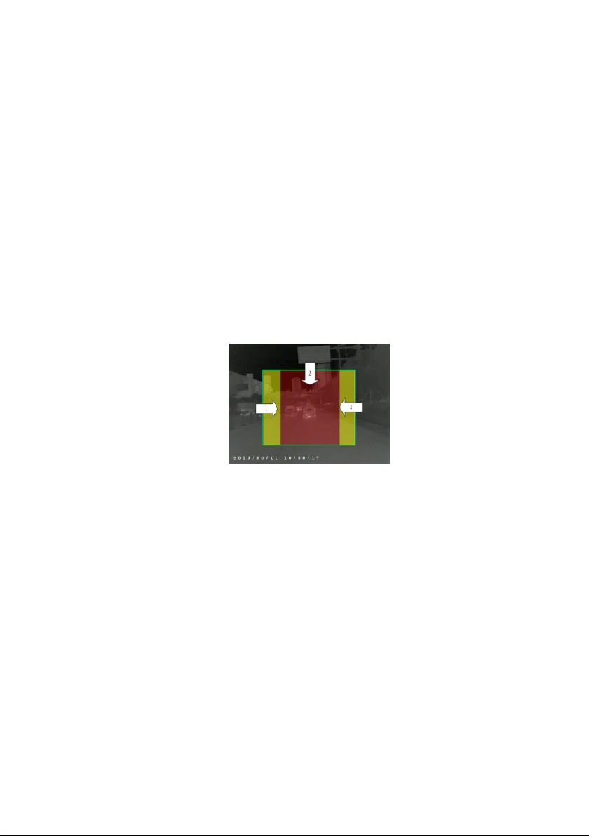
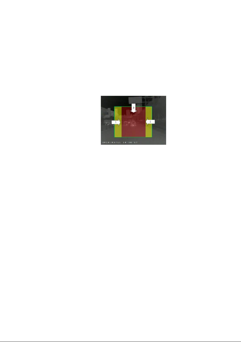
1) Pedestrian identification
Fig. 7 Scope of pedestrian identification
· The area pointed by arrow 1 and arrow 2 is the scope of
identification area. When the pedestrian target imaging is shown in this
area, the system will identify this and will mark the location with a
rectangular frame.
· The area pointed by arrow 2 is the alarm area. When the
system identifies that there will be risk of collision between the
pedestrian target and vehicle, it will give a warning prompt to the driver.
The area 15-45m ahead of the vehicle is red alarm area; the area
45-90m ahead of the forward vehicle is yellow alarm area.
16
· The area pointed by arrow 1 is the area for identification but not
for alarming. In other words, when the pedestrian target is shown in this
area, the system can only identify it and mark the location with a
rectangular frame, but it will not judge the level of danger caused by
collision.
2) Forward collision
Fig. 8 Scope of identification for forward collision
· The area pointed by arrow 1 and arrow 2 is the full scope of
identification area. When the forward target imaging is shown in this
area, the system will identify this and will mark the location with a
rectangular frame.
· The area pointed by arrow 2 is the alarm area. When the
system identifies that there will be risk of collision between the forward
vehicle and this vehicle, it will give a warning prompt to the driver. The
area 15-60m ahead of the vehicle is red alarm area; the area 60-120m
ahead of the forward vehicle is yellow alarm area.
· The area pointed by arrow 1 is the area for identification but not
for alarming. In other words, when the pedestrian target is shown in this
area, the system can only identify it and mark the location with a
rectangular frame, but it will not judge the level of danger caused by
collision.

17
· The area pointed by arrow 2 is the alarm area. When the
system identifies that there will be risk of collision between the forward
vehicle and this vehicle, it will give a warning prompt to the driver. The
area 15-60m ahead of the vehicle is red alarm area; the area 60-120m
ahead of the forward vehicle is yellow alarm area.
3) Pedestrian priority
The Infrared thermal imaging automobile driving assistant system
integrates pedestrian identification alarm and forward collision alarm,
when both of which occur simultaneously, the system will adopt the
principle of pedestrian priority:
· When the pedestrian and forward vehicle are in the same level
of danger, the system will preferentially give an alarm to the driver to
indicate danger of running into pedestrian.
· When the pedestrian and forward vehicle are in the same level
of danger, the system will preferentially give an alarm to the driver to
indicate danger of collision with the highest danger class.
· When there is no danger of simultaneous collision with
pedestrian and forward vehicle, the system will only give an alarm to the
driver to remind that there is target of collision risk.
· When there is neither risk of collision between the pedestrian
nor the forward vehicle, the system will not given an alarm to the driver.
4) Alarming mode
Mode for pedestrian alarming is shown as below:
· Serious warning will show red pedestrian sign, and the buzzer
will beep for three times; early warning will show yellow pedestrian sign,

18
and the buzzer will beep for once.
Fig. 9 Pedestrian alarming icon
Mode for forward collision alarming is shown as below:
· When the pedestrian and forward vehicle are in the same level
of danger, the system will preferentially give an alarm to the driver to
indicate danger of collision with the highest danger class.
Fig. 10 Alarming icon for forward collision
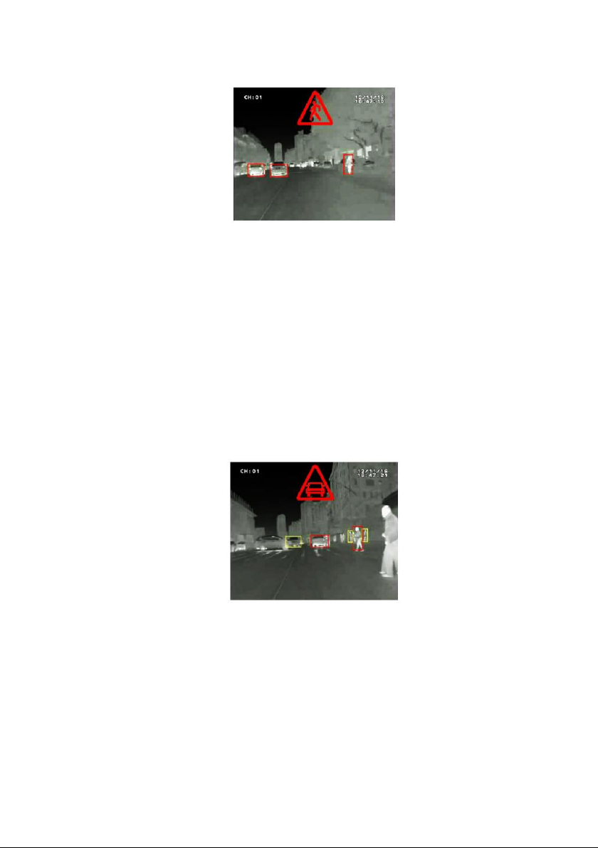
5) Image switching in different speed modes
· High speed mode:
When the vehicle runs at a speed of over 80Km/h and run straight
forward, the center area of the image will be shown by magnifying by 1.5
times. Pedestrian identification range can reach 135m and forward
vehicle identification range can reach 180m, which are shown in Fig. 11.
19
Fig. 11 Typical drawing of alarming (pedestrian and forward vehicle
giving an alarm simultaneously)
· Non-high-speed mode:
When the vehicle runs at a speed of less than 30Km/h, the area
on the left side of the image will be shown by magnifying 1.5 times
when the vehicle turns left, and the area on the right side of the
image will also be shown by magnifying by 1.5 times. As shown in
Fig. 12.
Fig. 12 Typical drawing of alarming (pedestrian and forward vehicle
giving an alarm simultaneously)

20
3. Technical Specifications of Product
Detector
Type of
detector
Noncrystalline silicon non-cooling focus plane 384 x 288
Image display performance
Effective focal
distance
19mm
Visual angle
28°x 21°(PAL),27°x 18°(NTSC)
Spatial
resolution
1.3mrad
Video output
interface
Single-end/difference
Video output
format
CVBS
Frame
frequency and
resolution of
output image
50Hz,768×576@PAL or 60Hz,720×480@NTSC
System characteristics
Table of contents
Popular Automobile Accessories manuals by other brands


Victory 4x4
Victory 4x4 2ND GEN COLORADO ROOF RACK Install instructions

Victory 4x4
Victory 4x4 ROOF RACK SIDE ACCESSORY MOUNT Install instructions

Steinhof
Steinhof F-143 FITTING AND OPERATION MANUAL

Pioneer
Pioneer HR 1500 PTO Installation, operation & maintenance manual

Bestop
Bestop Supertop NX Twill installation instructions

Lund
Lund Interceptor installation instructions


