www.pioneercoverall.com 5 866-353-5826
Hoses and fittings for connecting the diverter to the pump, the diverter to the hoist
controls, the cover control valve to tank, are not supplied because of the many places
these parts can be mounted.
NOTE: USE ONLY PIPE DOPE SUCH AS RECTORSEAL ON PIPE THREADS
DO NOT USE TEFLON TAPE!!!
Follow the hydraulic schematic and make the proper connections from the pump or
valve to the flow diverter, from the diverter to the hoist control (excess flow side)
(if necessary), from the diverter to the Cover Control Valve (priority side), from the
cover control valve back to tank and from the PRV back to tank. Hoses that are used
to make these connections must be equivalent to the original equipment provided by
the hoist manufacturer. If the Diverter are is installed between the pump and the hoist
control, set the Diverters’ PRV, 100 PSI higher than the hoist. If the Diverter is
installed after the hoist control (downstream) then the Diverters’ PRV can be set to
match the pressure required by the hydraulic motor.
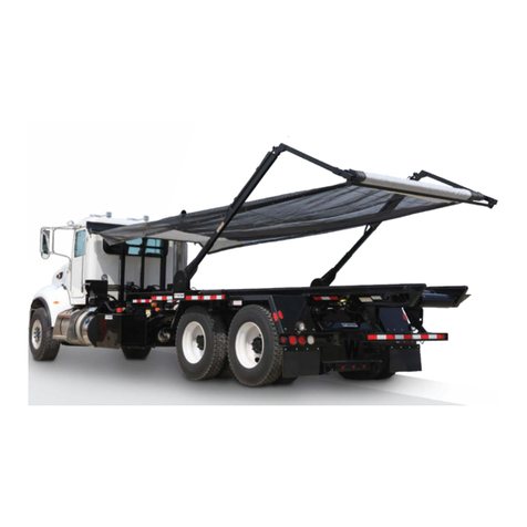
3. ACTIVATING THE GANTRY LIFT CYLINDER
Follow the hydraulic schematic and install the proper fittings into the gantry lift
cylinder. Attach –1- 9’ hose to the rod end fitting on the cylinder and attach –1- 6’
hose to the base end fitting on the cylinder.
The valve section labeled “UP – DOWN” is used to control the vertical motion of the
gantry. Install –2- elbows onto the top of this section. Lead the hoses from the gantry
cylinder toward the cover control valve using wire ties etc. to secure the hoses along
the way. Connect the hoses to the elbows on top of the valve. At this point it doesn’t
matter which hose goes to which side of the valve. They can be swapped later on.
To bleed the lines, start the truck and engage the PTO. Operate the “UP-DOWN”
valve in both directions to fill the cylinder with oil. Operate the valve so the cylinder
moves upward. Move the cylinder to the end of its stroke crack open the fitting at the
rod end of the cylinder to let any air escape that may be trapped in the cylinder. Re-
tighten the fitting and move the cylinder downward to its collapsed position. Crack
open the fitting at the base end of the cylinder to let any air escape that may be
trapped in the bottom of the cylinder. Re-tighten the fitting and run the gantry up and
down a few times to force any air in the cylinder or lines back to tank. If the hoses are
reversed, that is, if the gantry goes up when the handle is moved to the down position,
exchange the hoses. Re-bleed if necessary.
Apply a dry film lubricant (Dry Moly) to the telescopic gantry legs to cut down on
friction when moving up and down.
The relief valve on the left front of the cover control valve has been factory pre-set. If
the gantry does not move smoothly or if the hydraulic motor does not wind the cover
onto the roller smoothly when the cover control valve has been engaged, the the relief
valve may need to be adjusted. This is done as follows:
Remove the acorn cap that covers the adjusting screw.
Loosen the Jam Nut.
Turn the screw ¼ turn clockwise and try the system.
