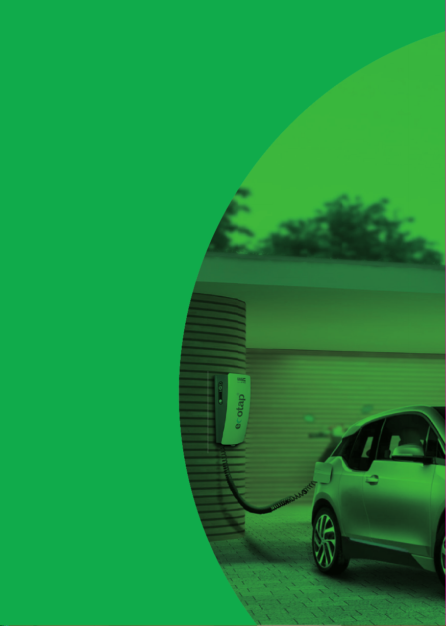
Ecotap Homebox User manual

Homebox
Handboek | Manual | Anleitung
Model 2019
YOU’RE IN CHARGE
NEDERLANDS
2

3
INHOUDSOPGAVE
1 Inleiding 4
2 Algemeen 5
2.1 Garantie 5
2.2 Symbolen in deze handleiding en laadsysteem 5
3 Apparaat omschrijving 5
3.1 Toepassing 5
3.2 Accessoires 5
3.3 Veiligheidsvoorzieningen 6
4 Veiligheid 6
4.1 Veiligheidsvoorschriften 6
5 Verplichte controles voor ingebruikname 7
6 Gebruik / installatie handleiding 7
6.1 Vereiste voedingskabel 7
6.2 Montage op de wand of speciaal rek 7
7 Onderhoud 9
8 Transport en opslag 9
9 Storing uitleg 9
10 Werking en bediening laadsysteem 9
11 Technische specificaties 10
12 Contactgegevens leverancier 11
13 EG-Verklaring van overeenstemming 11
ENGLISHNEDERLANDS

4
1. INLEIDING
Hartelijk dank dat u hebt gekozen voor een Homebox van Ecotap®.
Deze handleiding beschrijft de Homebox met laad contact doos alsmede
een vaste kabel type 1 of 2 in de varianten met en zonder registratie.
In deze handleiding staat belangrijke informatie voor een goede en veilige
installatie en gebruik van het laadsysteem.
De Homebox is ontworpen voor voertuigen die voorzien zijn van een mode
3 laadsysteem conform IEC 61851-1 (editie2.0) met stekkersysteem conform
VDE-AR-E 2623-2-2.
Het gehele laadsysteem voldoet aan de richtlijn 2014/35/EU betreffende de
harmonisatie van de wetgevingen betreffende elektrisch materiaal binnen
bepaalde spanningsgrenzen (herschikking van alle eerdere uitgebrachte
versies).
De handleiding geeft inzicht hoe de Homebox veilig geïnstalleerd en
gebruikt kan worden. Deze handleiding is opgesteld zodat de werking en
levensduur van de Homebox maximaal zullen zijn.
Deze handleiding is met grote zorg opgesteld. Echter, mochten er toch nog
onduidelijkheden zijn, neem dan contact op met uw leverancier alvorens u
de Homebox gaat installeren.
Het goed functioneren van de Homebox kan uitsluitend worden
gegarandeerd indien de montage van de Homebox door gemachtigde of
erkende installateur / monteur wordt uitgevoerd. Als de Homebox niet door
een erkende installateur wordt aangesloten kan dit gevolgen hebben voor
de garantie van het toestel.
Lees deze handleiding nauwkeurig door voordat u het laadsysteem gaat
installeren en gebruiken. Bewaar deze handleiding in de omgeving van
het laadsysteem zodat de instructies en veiligheidsvoorschriften altijd
voorhanden zijn.
© Copyright
Niets uit deze uitgave mag worden gekopieerd, vermenigvuldigd of worden
opgeslagen in een retrieval systeem zonder schriftelijke toestemming van
Ecotap® B.V.
Dit is de oorspronkelijke handleiding, geschreven in de Nederlandse taal.
ENGLISH
NEDERLANDS

5
2. ALGEMEEN
2.1 Garantie
Hier gelden de Algemene leveringsvoorwaarde van Ecotap® B.V.
Ecotap® B.V. kan niet aansprakelijk worden gesteld voor letsel of schade
indien het laadsysteem wordt gewijzigd, beschadigd, omgebouwd of wordt
uitgebreid met andere componenten of niet wordt gebruikt volgens de
gestelde instructies en voorwaarden.
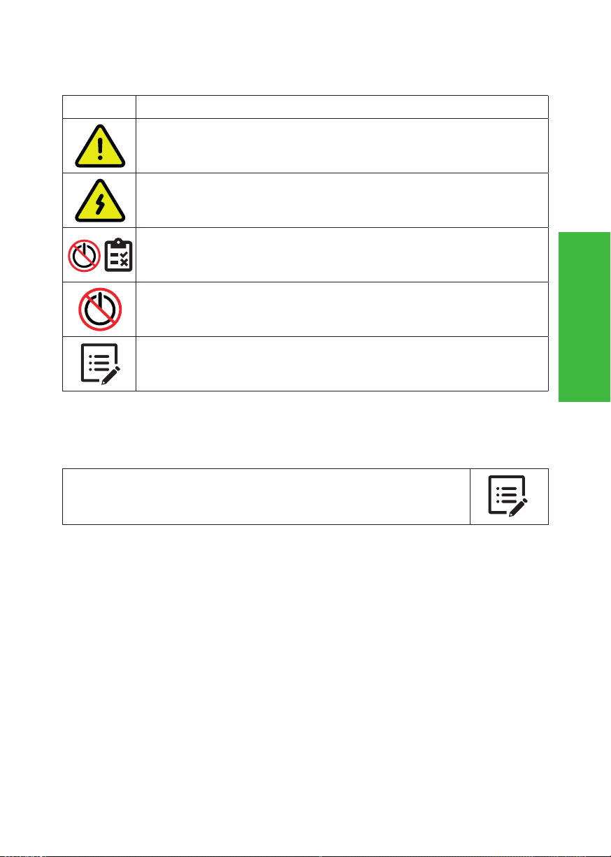
2.2 Symbolen in deze handleiding en laadsysteem
Symbool Betekenis
Let op!
Belangrijke instructie.
Elektrisch gevaar.
Bij onderhoud: eerst spanningsvrij maken en diverse
meettesten uitvoeren alvorens onderhoud te plegen.
Spanningsvrij maken van elektrische installatie.
Handleiding lezen verplicht.
3. APPARAAT OMSCHRIJVING
3.1 Toepassing
De Homebox is speciaal ontworpen om tegen wanden of op
een (speciaal daarvoor gemaakt) montagerek gemonteerd te
worden.
3.2 Accessoires
De volgende accessoires maken geen deel uit van de leveringsomvang:
- Gereedschappen
- Montagerek
ENGLISHNEDERLANDS
6
3.3 Veiligheidsvoorzieningen
- Zekering houders
- 12 Volt stuurspanning
- Componenten minimaal IP2
- Trekontlastingen
- 2,5 mm stalen behuizing
- IP54 laagste waterdichtheid klasse van de type 2 stopcontacten
- IP55 in combinatie met Flex type 2 stekker
4. VEILIGHEID
Lees de volgende veiligheidsvoorschriften goed door voordat u
het laadsysteem gaat installeren en in gebruik gaat nemen.
4.1 Veiligheidsvoorschriften
Voordat u de Homebox gaat monteren maakt u de locatie veilig voor
omstanders.
Laat op deze werkplek NOOIT kinderen toe. Zorg dat NIEMAND die niets met
de werkzaamheden heeft te maken op de werkplek komt.
Laat u nooit afleiden tijdens de werkzaamheden.
Zorg te allen tijde voor een gezonde houding tijdens u werkzaamheden.
Laat gereedschappen en onderdelen van de Homebox niet onbeheerd.
Zorg dat het gereedschap schoon en droog is.
Tijdens slecht weer met regenval zorgen dat Homebox, gereedschap en
onderdelen droog blijven.
Zorg te allen tijde dat bij het spanningsvrij maken van de
installatie het meetinstrument, dat voor het controleren
hiervan, meerdere malen wordt gecontroleerd op werking.
ENGLISH
NEDERLANDS
7
5. VERPLICHTE CONTROLES VOOR INGEBRUIKNAME
De volgende controles zijn verplicht voor de installatie / inge-
bruikname van de Homebox. Gebruik de Homebox NOOIT als
bij 1 of meerdere controles blijkt dat stroomtoevoer of stabiliteit
van de Homebox niet voldoet.
Voer de onderstaande controles altijd uit voordat er spanning
op de Homebox wordt gezet.
√Alle onderstaande werkzaamheden dienen volledig conform NEN 3140
√Controleer of de aansluitklemmen goed zijn vastgedraaid (3,5 tot 5 NM).
√Controleer of de aardverbinding is gemaakt met de aangeleverde aarding.
√Controleer of de kabeldikte van de voedingskabel klopt met de gezekerde
stroomwaarde.
√Controleer of de Homebox vast en stevig is gemonteerd.
√Controleer de waterbestendigheid van de invoerwartels.
√Houd de omgeving van de werkplek vrij van obstakels.
6. GEBRUIK / INSTALLATIE HANDLEIDING
6.1 Vereiste voedingskabel
De voedingskabel moet op een aparte groep in de verdeler /
meterkast aangesloten worden. Bij een automaat dient dit een
C of D karakteristiek te zijn of gelijkwaardig. De bekabeling zal
volledig moeten voldoen aan de NEN1010.
Uitzonderingen op de NEN1010 zijn:
- Aardverspreiding weerstand < 30 Ohm.
- Installatieweerstand < 2 Ohm.
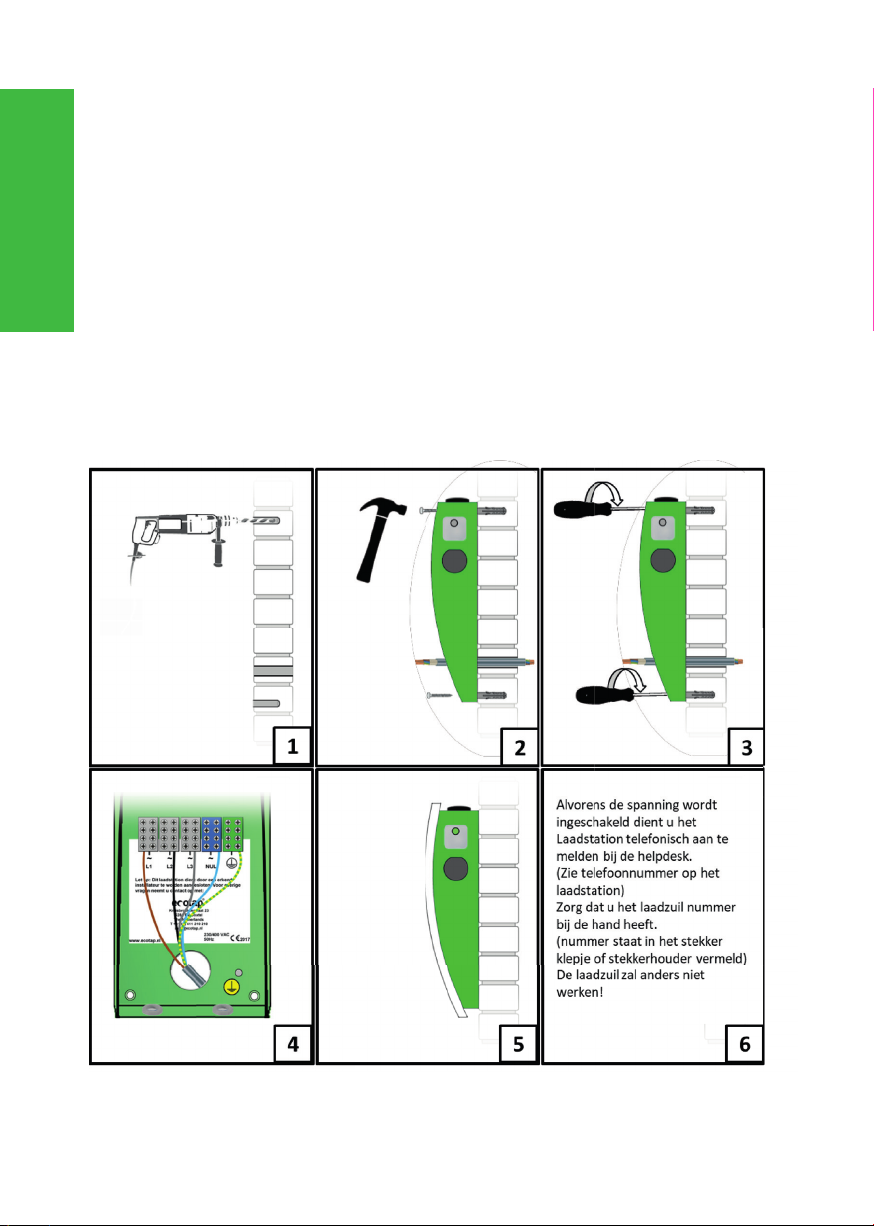
6.2 Montage op de wand of speciaal rek
De Homebox monteert u het beste op een hoogte van +/- 100
centimeter, gemeten vanaf de onderzijde van de Homebox.
Verwijder eerst het stalen schild middels de torx schroef aan
de onderzijde. Voer de kabel in de Homebox en fixeer de kabel
met de kabelwartel.
(De kabel kan zowel vanuit de achterwand alsmede via de
bestaande wartelingang aan de onderzijde worden ingevoerd).
ENGLISHNEDERLANDS
8
De Homebox monteert u het beste op een hoogte van +/- 100 centimeter,
gemeten vanaf de onderzijde van de Homebox.
Verwijder eerst het stalen schild middels de torx schroef aan de onderzijde.
Voer de kabel in de Homebox en fixeer de kabel met de kabelwartel.
(De kabel kan zowel vanuit de achterwand alsmede via de bestaande
wartelingang aan de onderzijde worden ingevoerd).
Gebruik bij het vastzetten van de aders de juist passende schroevendraaier
en zet deze vast met min. 3,5Nm. Vergeet de losse aarddraad vanuit
de Homebox niet te bevestigen op de losse deksel. Gebruik de juiste
bijgeleverde bevestigingsschroeven om de Homebox stevig vast te zetten op
een wand/muur/rek.
Bij het speciaal montagerek dient de kabel door de open ruimte van de
constructie te worden geleid. Het montage-rek dient minimaal 70 (max. 90)
centimeter in de ondergrond te worden aangebracht en indien nodig door
een betonsoort te worden gefixeerd.
ENGLISH
NEDERLANDS

9
7. ONDERHOUD
Maak de Homebox altijd spanningsvrij en lees de
gebruiksaanwijzing voordat je onderhoud of storingen gaat
behandelen.
Reparatie of vervangen van componenten mag alleen met de
door de leverancier goed bevonden producten.
Reparaties en vervangingen dienen altijd door een bevoegd /
erkend installateur te worden uitgevoerd. Het onderhoud moet
altijd voldoen en worden uitgevoerd conform NEN3140 en NEN
50110 laagspanning euro norm.
Beschadigingen aan de Homebox behandelen met roestwe-
rende verf.
8. TRANSPORT EN OPSLAG
Vervoer de Homebox in de bijgeleverde doos zoals u deze heeft ontvangen.
Als u de Homebox verstuurt, geef dan goed aan dat het met enige
voorzichtigheid behandeld dient te worden.
9. STORING UITLEG
Bij niet functioneren van het laadsysteem kunt u contact opnemen met de
helpdesk (zie telefoonnummer op laadstation) of een erkend installateur die
beschikt over meet en test apparatuur met autosimulatie.
10. WERKING EN BEDIENING LAADSYSTEEM
De Homebox is te bedienen met een laadpas, drukknop of is
zelfstartend.
De Homebox uitvoering “Laden Met Registratie / LMR” dient nog wel te
worden geregistreerd. Zodra de registratie is voltooid, is de Homebox te
gebruiken met elke geschikte laadpas. De Homebox geeft in ongebruikte
staat met enige regelmaat een oplichtende groen signaal.
Werking
De laadprocedure kan worden gestart en gestopt door de laadpas voor het
scan-punt te houden of de startknop in te drukken (alleen bij drukknop
uitvoering). U hoort 1 geluidsignaal en de lamp gaat groen knipperen.
Bij een laad contact doos uitvoering wordt de stekker vergrendeld in de type
2 laadcontactdoos. Daarna communiceert het laadsysteem met het voertuig
ENGLISHNEDERLANDS

10
en het BackOffice systeem. Als alle veiligheid en betalingsvoorschriften zijn
gecontroleerd wordt de maximale toelaatbare laadstroom doorgegeven.
De oplaadprocedure wordt nu automatisch ingeschakeld en de lamp gaat
blauw branden.
Bij het stoppen van het laadproces houdt u de pas voor het scanpunt
of drukt u de knop in (alleen bij drukknop uitvoering). U hoort 2
geluidssignalen, de lamp gaat groen knipperen en stopt totdat de stekker
wordt ontgrendeld. U kunt deze nu verwijderen.
De uitvoering met een flexibele/ spiraalkabel slaat de ver/ontgrendeling in de
Homebox over.
De drukknop/autostart bediening vervangt het scanpunt en heeft geen
controle van het BackOffice nodig om te kunnen schakelen.
11. TECHNISCHE SPECIFICATIES
Aantal laadpunten: 1
Uitgangsvermogen per laadpunt: 22 Kw
Contactdoos: Type 2
Flex Kabel: Type 1 of Type 2
Protocol: Mode 3
Positiebepaling: GPS (bij registratie)
Communicatie: GSM Modem/ Controller met RFID
reader (bij registratie)
Aansluitwaarde: 1x 16A tot 3x 32A
Output voltage: 230 V/ 400 V 50 Hz
Totaal gewicht: met contactdoos:
met Flex Kabel:
10 Kg
12 Kg
Afmeting behuizing HxBxD: 530 mm x 220 mm x 200 mm
Materiaal behuizing: Staal 2,2 mm
Standaard kleur: RAL 7011/RAL 9016
Waterbestendigheid: IP 54
Vandalismebestendigheid: IK 10
Behandeling: Anti corrosie en poedercoating
Bedrijfs- / Omgevingstemperatuur: -25°- tot 60°
Ecotap® B.V. behoudt zich het recht voor om zonder voorafgaande
kennisgeving de bovenstaande technische gegevens te wijzigen als gevolg
van voortgaande, innovatieve ontwikkelingen van het laadstation. De
technische gegevens kunnen bovendien van land tot land verschillend zijn.
ENGLISH
NEDERLANDS

11
12. CONTACTGEGEVENS LEVERANCIER
Ecotap® B.V.
Kruisbroeksestraat 23
5281RV Boxtel – The Netherlands
Tel.: 0031 (0) 411-210210
E-mail: inf[email protected]
13. EG-VERKLARING VAN OVEREENSTEMMING
Verklaring van overeenstemming voor machines
(richtlijn 2014/35/EU, Bijlage II blz.96/369)
Hierbij verklaart Ecotap® B.V. Kruisbroeksestraat 23 4 5281RV Boxtel, dat
de hierna genoemde Laadstations overeenstemt met de eisen van de
Machinerichtlijn en de andere hierna genoemde richtlijnen en Normen.
Type: Ecotap® Homebox type lcd/flex type 1 & 2 Ontwerpjaar : 2019
Gehanteerde EG-Richtlijnen:
• Laagspanningsrichtlijnen 2014/35/EU
• EMC-richtlijn 2014/30/EU
• EN / IEC 60950-22/2017
• EN / IEC61851-1/2017
• EN/IEC61851-22/2002
• EN/IEC 62196-2/2017
• EN IEC 61000-6-2/2016
• EN IEC 61000-6-3/2007 + A1/2011
• EN / IEC 60335-1/2012 + A13/2017
• EN/IEC 60364-4-41/2017
Boxtel, April 2019
Ir. P.F.A. van der Putten (Technical Director)
ENGLISHNEDERLANDS

ENGLISH
12

13
TABLE OF CONTENTS
14 Introduction 14
15 General 14
15.1 Warranty 14
15.2 Symbols used in this manual and on the
charging system 15
16 Description of equipment 15
16.1 Application 15
16.2 Accessories 15
16.3 Safety features 15
17 Safety 16
17.1 Safety instructions 16
18 Mandatory checks before commissioning 16
19 Operation / installation manual 17
19.1 Requirements for the power cable 17
19.2 Mounted on a wall or on a special rack 17
20 Maintenance 18
21 Transportation and storage 18
22 Resolving problems 18
23 Operation of the charging system 18
24 Technical specifications 19
25 Contact details supplier 20
26 EG conformity statement 20
ENGLISHENGLISH

14
14. INTRODUCTION
Thank you for selecting the Ecotap® Homebox.
This manual describes the Homebox with socket and fixed charging cable
type 1 or 2 for versions with and without registration.
This manual contains important information on correct and safe installation
and use of the charging system.
The Homebox was designed for vehicles fitted with a mode 3 charging
system in conformity with IEC 61851-1 (edition 2.0) with a plug system that
conforms to VDE-AR-E 2623-2-2.
The charging system as a whole complies with directive 2014/35/EU on
harmonisation of the laws relating to electrical materials within certain
voltage limits (recasting of all earlier published versions).
This manual provides information on safe installation and use of the
Homebox. This manual was drawn up to ensure optimum operation and
lifespan of the Homebox.
This manual was drawn up with great care. However, if anything in the
manual is unclear, please contact your supplier before installing the
Homebox.
Proper operation of the Homebox can only be guaranteed if the Homebox is
installed by an authorised installer / engineer. If the Homebox is not installed
by an authorised installer, this may affect the product warranty.
Please read this manual carefully before installing and using this
charging system. Store this manual in the vicinity of the charging system
for easy access to the instructions and safety regulations.
© Copyright
No part of this publication may be copied, replicated or stored in a retrieval
system without the permission of Ecotap® B.V.
The original version of this manual was written in the Dutch language.
15. GENERAL
15.1 Warranty
The General Terms of Delivery of Ecotap® B.V. apply.
Ecotap® B.V. cannot be held liable for any injury or damage if the charging
system has been changed, damaged, converted or extended with other
components or if the instructions and conditions have not been observed.
ENGLISH
ENGLISH
15
15.2 Symbols used in this manual and on the charging system
Symbol Meaning
Please note!
Important instruction
Electrical danger
For maintenance: First, switch off power and carry out
various measurement tests before starting maintenance work
Switching off the power of the electrical installation
The manual must be read first
16. DESCRIPTION OF EQUIPMENT
16.1 Application
The Homebox was specially designed to be mounted on a wall
or on a special mounting rack.
16.2 Accessories
The following accessories are included in the scope of delivery:
tools, mounting frame
16.3 Safety features
- Fuse boxes
- 12 Volts control voltage
- Components at least IP2
- Strain reliefs
- 2.5 mm steel casing
- IP54 lowest waterproof class of type 2 sockets
- IP55 in combination with Flex type 2 plug
ENGLISHENGLISH
16
17. SAFETY
Please read the following safety regulations with care before
installing and using the charging system.
17.1 Safety instructions
Before you install the charging station, you must make sure the location is
safe for all bystanders. NEVER allow children onto this worksite. Never allow
ANYONE who has nothing to do with the work onto the worksite.
- Never be distracted while you are performing the work.
- Make sure you maintain a healthy posture at all times while doing the work.
- Do not leave any tools or charging station components unattended.
- Make sure any tools you are using are clean and dry.
- Make sure that the charging station, tools and components will stay dry
when it is raining.
When switching off the power of the system, always make
sure the measurement instrument used for testing this is
checked for proper operation repeatedly.
18. MANDATORY CHECKS BEFORE COMMISSIONING
The following checks are mandatory before commissioning the
Homebox. NEVER use the Homebox if 1 or more checks indica-
te that the power supply or the stability of the Homebox does
not meet the requirements.
Always perform the following checks before switching on the
power supply of the Homebox
√All the following work must be carried out in full conformity with NEN 3140.
√Check if the terminals have been properly tightened (3.5 to 5 NM).
√Check the earth connection.
√Check if the power cable thickness matches the fuse value.
√Check if the Homebox has been mounted securely.
ENGLISH
ENGLISH
17
√Check if the cable glands are watertight.
√Keep the area around the workplace free of obstacles.
19. OPERATION / INSTALLATION MANUAL
19.1 Requirements for the power cable
The power cable must be attached to a separate group in the
distributor / meter cupboard. For an automatic system, this
must be the C or D characteristic or equivalent. Cabling must
be in full conformity with NEN1010.
Exceptions to NEN1010 are:
- Earth distribution resistance < 30 Ohm.
- Installation resistance < 2 Ohm.
19.2 Mounted on a wall or on a special rack
The Homebox should preferably be mounted at a height of +/-
100 centimetres, measured from the lower edge of the
Homebox.
First remove the steel shield by removing the torx screw at the bottom.
Guide the cable into the Homebox and secure the cable using the cable
gland. (The cable can be guided into the system via the back or via the cable
gland opening at the bottom).
Connect the wires in the way indicated on the terminator strip.
Connect the phase wires* to the terminals L1 / L2 / L3.
Connect the neutral wire to the neutral terminal.
Connect the shielding/earthing wire to the neutral terminal.
(*This can be 1-phase or 3-phase, depending on the available power source.
If you want to use 1-phase, connect to Phase 1 and to Neutral and Earth.)
Use the proper screwdriver size for connecting the wires, and tighten the
screws with a torque of at least 3.5Nm. Do not forget to connect the loose
earthing wire from the Homebox to the loose cover.
Use the correct screws included to securely fix the Homebox to the wall or
rack.
When using the special mounting rack, the cable must be guided through
the opening of the structure. The mounting rack must be sunk at least 70
centimetres (max. 90) into the underground and may need to be anchored
in concrete.
ENGLISHENGLISH
18
20. MAINTENANCE
Always switch off the power and read the user manual before
carrying out maintenance or fixing problems.
Only products approved by the supplier must be used for
repairs or replacement of components.
Repairs and replacements must be carried out by an
authorised employee / installer. All maintenance work must
be carried out in compliance with the NEN3140 and NEN 50110
Euro standards for low-voltage equipment.
Treat any damaged surface areas of the Homebox with anti-corrosive paint.
21. TRANSPORTATION AND STORAGE
Transport the Homebox in the box it was delivered in. When shipping the
Homebox, apply a clear indication that the item must be handled with care.
22. RESOLVING PROBLEMS
If the charging system does not work properly, you can contact back office
provider or an authorised installer in possession of measurement and testing
equipment with car simulation.
23. OPERATION OF THE CHARGING SYSTEM
The Homebox can be operated either with a charging pass or with the
button, or the system is self-starting.
The Homebox version “Laden Met Registratie / LMR” (Charging with
registration) needs to be registered.
This registration is possible by calling Ecotap® B.V. during office hours.
Tel. +31 (0) 411 74 50 20.
As soon as registration is completed, the Homebox can be used with any
Electric Transport charging pass, or other suitable pass.
When the Homebox is not in use, a green light will flash regularly.
Operation:
The charging procedure can be started and stopped by holding the charging
pass in front of the scan point, or by pressing the Start button (only for the
version with a Start button). You will hear 1 audio signal and the light starts
blinking green.
With the version with a type 2 socket, the plug is locked in the type 2
charging socket. The charging system then communicates with the vehicle
and with the back office system. Once all safety and payment conditions
have been checked the maximum allowed charging current is released.
ENGLISH
ENGLISH

19
The charging procedure is automatically started and the light will flash blue.
To stop the charging process, hold your pass in front of the scan point or
press the button (only for the version with a button). You will hear 2 audio
signals, the light starts to blink green and stops when the plug is unlocked.
You can now remove the plug.
The version with a flexible/spiral cable does not lock/unlock the Homebox.
The button or autostart operation is used instead of the scan point; with this
version no back office check is needed to start the system.
24. TECHNICAL SPECIFICATIONS
Number of charging points: 1
Power output: 22 Kw
Socket: Type 2
Flexible coiled cord: Type 1 of Type 2
Protocol: Mode 3
Positioning: GPS (with registration)
Communication: GSM Modem / Controller with
RFID-reader (with registration)
Connection value: 1x 16A tot 3x 32A
Output voltage: 230 V/ 400 V 50 Hz
Total weight: with socket:
with coiled cord:
10 Kg
12 Kg
Casing dimensions HxWxD: 530 mm x 220 mm x 200 mm
Casing material: Steel 2,2 mm
Standard colour: RAL 7011/RAL 9016
Water resistance: IP 54
Vandalism resistance: IK 10
Treatment: Anti-corrosion and powder coating
Operating/ambient temperature: -25°- tot 60°
Ecotap® B.V. reserves the right to change the above technical data without
prior notice as a result of continued innovative development of the charging
system. Please note also that the technical data may vary between countries.
ENGLISHENGLISH

20
25. CONTACT DETAILS SUPPLIER
Ecotap® B.V.
Kruisbroeksestraat 23
5281RV Boxtel – The Netherlands
Tel.: 0031 (0) 411-210210
E-mail: inf[email protected]
26. EG CONFORMITY STATEMENT
Statement of conformity for machines
(Directive 2014/35/EU, Annex II page 96/369)
Ecotap® B.V. Kruisbroeksestraat 23, 5281RV Boxtel, the Netherlands, hereby
states that the following charging systems meet the requirements of the
listed directives and standards.
Type: Ecotap® Homebox type lcd/flex type 1 & 2 Design year: 2019
Installation guidelines
• Low Voltage directive 2014/35/EU
• EMC-Directives 2014/30/EU
• EC / IEC 60950-22/2017
• EN / IEC61851-1/2017
• EN/IEC61851-22/2002
• EN/IEC 62196-2/2017
• EN IEC 61000-6-2/2016
• EN IEC 61000-6-3/2007 + A1/2011
• EN / IEC 60335-1/2012 + A13/2017
• EN/IEC 60364-4-41/2017
Boxtel, April 2019
Ir. P.F.A. van der Putten (Technical Director)
ENGLISH
ENGLISH
Table of contents
Languages:
Other Ecotap Automobile Accessories manuals

Popular Automobile Accessories manuals by other brands

Toshiba
Toshiba B-EP802-DC12-QM-R owner's manual

SHOCKERHITCH
SHOCKERHITCH AIR EQUALIZER Setup instructions

Ecco
Ecco Reflex 5500 Series Installation and operating instructions

Safe Fleet
Safe Fleet PRIME DESIGN VBI-FT21B manual

Blaupunkt
Blaupunkt 7 608 502 000 installation instructions

Mid America Motorworks
Mid America Motorworks 648-740 installation instructions


Scosche
Scosche BTFREQ BTFM5 manual

GReddy
GReddy Intercooler Kit installation manual

Thule
Thule Transporter Combi 665C installation instructions

Kogan
Kogan KABLU41KITA quick start guide

Dynojet
Dynojet POWER COMMANDER III USB EX installation instructions

M-Way
M-Way STEEL BIKE STARFIGHTER x2 Fitting instructions