Ecreso HELIOS JUNIOR User manual

HELIOS JUNIOR
MONO MULTIPLEX 20 W TRANSMITTER
USER MANUAL
FM TRANSMITTER 87,5-108MHz
Date: 2008/02/22
Ecreso
web: www.ecreso.com - e-mail: contact@ecreso.com


Helios Junior, User’s guide 02/2008
Page 3
ECRESO – 20, avenue Neil Armstrong – Parc d’Activites JF Kennedy – 33700 Bordeaux-Merignac – France
TABLE OF CONTENTS
1. INTRODUCTION.......................................................................................................................................5
1.1. INTRODUCTION .................................................................................................................................5
1.2. PACKING ..........................................................................................................................................5
1.3. GUARANTEE CLAUSES .......................................................................................................................5
1.4. SAFETY INSTRUCTIONS......................................................................................................................6
1.5. RADIO AND TELEVISION INTERFERENCES............................................................................................6
2. DESCRIPTION..........................................................................................................................................7
2.1. GENERAL DESCRIPTION .....................................................................................................................7
2.2. HELIOS JUNIOR FRONT PANEL............................................................................................................ 8
2.3. HELIOS JUNIOR BACK PANEL.............................................................................................................. 9
2.4. DETAILED DESCRIPTION OF THE HELIOS JUNIOR .............................................................................10
2.4.1. 1U Rack.................................................................................................................................11
2.4.2. Power supply.........................................................................................................................11
2.4.3. Main board.............................................................................................................................11
2.4.4. RF amplifier part....................................................................................................................11
2.4.5. Monitoring/ Display part.........................................................................................................11
3. TECHNICAL SPECIFICATIONS ............................................................................................................13
3.1. RF SECTION :..................................................................................................................................13
3.2. COMPOSITE OPERATION : ................................................................................................................13
3.3. MONAURAL OPERATION: ..................................................................................................................13
3.4. AF INPUTS:.....................................................................................................................................13
3.5. COMMAND INPUT:............................................................................................................................13
3.6. HF OUTPUT: ...................................................................................................................................14
3.7. POWER SUPPLY: .............................................................................................................................14
3.8. INTERFACE PANEL: .......................................................................................................................... 14
3.9. ENVIRONMENT : ..............................................................................................................................14
3.10. PHYSICAL: ..................................................................................................................................14
3.11. OTHER:.......................................................................................................................................15
3.12. SPARE PARTS:.............................................................................................................................15
4. USE.........................................................................................................................................................16
4.1. OPERATION DESCRIPTION................................................................................................................16
4.1.1. Reset .....................................................................................................................................16
4.1.2. Configuration menu ...............................................................................................................16
4.2. MENUS SELECTION.......................................................................................................................... 16
4.3. SYNOPTIC OF DIFFERENT MENUS .....................................................................................................18
5. INSTALLATION......................................................................................................................................24
5.1. PHYSICAL SET-UP ...........................................................................................................................24
5.1.1. Input settings (MONO or MPX) .............................................................................................24
5.1.2. Pre-emphasis (ONLY IN MONO) ..........................................................................................25
5.1.3. Input range (MONO and MPX).............................................................................................. 25
5.2. INSTALLATION .................................................................................................................................26
5.3. CONNECTIONS ................................................................................................................................26
5.3.1. Load test................................................................................................................................27
5.3.2. Mains connection ..................................................................................................................27

Helios Junior, User’s guide 02/2008
Page 4
ECRESO – 20, avenue Neil Armstrong – Parc d’Activites JF Kennedy – 33700 Bordeaux-Merignac – France
6. SET-UP ...................................................................................................................................................29
6.1. RECOMMENDED TEST EQUIPMENT ....................................................................................................29
6.2. SET-UP...........................................................................................................................................29
6.2.1. Setting of parameters ............................................................................................................30
6.2.2. Information screen.................................................................................................................31
6.3. INDICATORS AND ALARMS ................................................................................................................32
7. MAINTENANCE......................................................................................................................................34
7.1. PREVENTIVE MAINTENANCE .............................................................................................................34
7.2. REPAIR...........................................................................................................................................34
GLOSSARY ................................................................................................................................................36
MORE INFORMATION ...............................................................................................................................39
Helios Junior, User’s guide 02/2008
1. INTRODUCTION
1.1. Introduction
This user’s guide includes information about installation, set-up, tests for the use of the Helios Junior
transmitter. It describes the operation of the equipment and tackles mechanical, electrical and safety
features.
For further technical information or for information about a more specific use, please contact your
distributor.
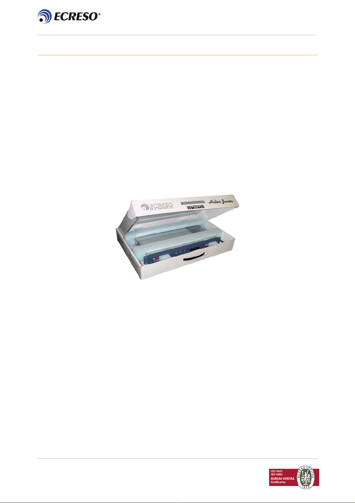
1.2. Packing
The HELIOS Junior transmitter is packed in a box containing two foam protections, to protect the
equipment from mechanical shocks and vibrations during transport. It is recommended to keep this
packing in case you need to send back the equipment. Particularly, connectors should be protected.
Packing box
In the box, you will find the following accessories:
¾1 AC power cord.
¾1 anti-pulling clip to mount on the mains filter (anti-pulling for the AC power cord).
¾2 5x20 fuses of 1 AT.
¾1 adjustment screwdriver
¾User’s guide
Optional, additional manuals on paper or CD-ROM.
1.3. Guarantee clauses
This product has a legal guarantee, for parts and servicing, when returned to the manufacturer.
Guarantee extensions are possible.
Guarantee is not applicable to replacement nor repairing needed after damage or accident caused by
negligence, maintenance faults, installation faults or use in a non prepared location.
Page 5
ECRESO – 20, avenue Neil Armstrong – Parc d’Activites JF Kennedy – 33700 Bordeaux-Merignac – France

Helios Junior, User’s guide 02/2008
Page 6
ECRESO – 20, avenue Neil Armstrong – Parc d’Activites JF Kennedy – 33700 Bordeaux-Merignac – France
If the client modified or repaired without previous authorization, ECRESO company would be free from
any guarantee.
1.4. Safety instructions
This equipment respects international standards for electrical and mechanical safety. However, if the
equipment is operating with 230 V AC power supply, please unplug the equipment before any
intervention.
This manual does not include any information about workforce safety. Any intervention must be carried
out by qualified workforce, formed in safety.
1.5. Radio and Television interferences
This equipment generates, due to its operation, electromagnetic energy. Poor installation or poor use can
generate interferences or cause surrounding devices to work poorly.
The HELIOS Junior transmitter installed and used in accordance with specifications as defined by the
ECRESO company, respects CCIR and CEM standards for surrounding devices protection and perfect
isolation from those devices.
The RF connection to the HELIOS Junior transmitter must be done with coaxial cable within 50 ohms
impedance.
It is also recommended to harden other cables connected to connectors of the following types: BNC,
SUB-D, RJ11, RJ45 etc.
Helios Junior, User’s guide 02/2008
2. DESCRIPTION
2.1. General description
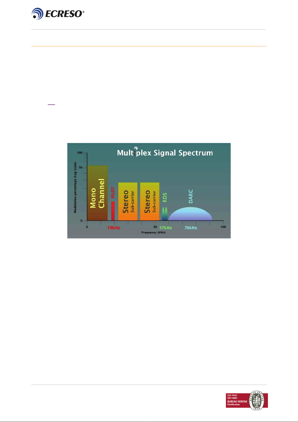
The HELIOS Junior transmitter is built for FM mono or multiplex program transmission (electric radio
signal type F3) in a frequency range between 87,5 and 108 MHz.
Its output power is at least equal to 20 watts under 50 ohms.
For an FM stereophonic transmission, you will have to use an external coder.
This transmitter is a standard 19 inch 1 unit rack.
Multiplex signal
Page 7
ECRESO – 20, avenue Neil Armstrong – Parc d’Activites JF Kennedy – 33700 Bordeaux-Merignac – France

Helios Junior, User’s guide 02/2008
2.2. Helios Junior front panel
Helios front panel
1 2 3 4 5 6 7 8 9 10
Front panel description:
1 Input level potentiometer of mono or multiplex signal (MONO/MPX).
2 Output power level potentiometer (RF POWER).
3 HF alarm indicator (RF 3dB).
4 VSWR alarm indicator (VSWR).
5 Synthesizer locking indicator (LOCK).
6 LCD back lighted display with 2 lines of 16 characters.
7 Menu selection button ( - ).
8 Parameter validation button (ENTER).
9 Menu selection button ( + ).
10 Molded transport handles.
Page 8
ECRESO – 20, avenue Neil Armstrong – Parc d’Activites JF Kennedy – 33700 Bordeaux-Merignac – France

Helios Junior, User’s guide 02/2008
2.3. Helios Junior back panel
Helios Junior back panel
1 2 3 4 5
Back panel description:
1 1earthing clip (GROUND).
2 1 sector block with a fuse holder, and a Start/Stop switch (MAINS INPUT).
3 Auxiliary multiplex input, female BNC socket (AUX).
4 Mono/multiplex input, female BNC socket (MONO/MPX).
5 HF output, female N socket (RF OUTPUT).
Page 9
ECRESO – 20, avenue Neil Armstrong – Parc d’Activites JF Kennedy – 33700 Bordeaux-Merignac – France

Helios Junior, User’s guide 02/2008
2.4. Detailed description of the HELIOS Junior
Transmitter’s view with open cover
Synthesizer
20W Amplifier Main
board
Main filter+
fuses
Switching
power supply
Page 10
ECRESO – 20, avenue Neil Armstrong – Parc d’Activites JF Kennedy – 33700 Bordeaux-Merignac – France
Rounded
front panel
LCD display Monitoring
part

Helios Junior, User’s guide 02/2008
Synoptic of the receiver
2.4.1. 1U Rack
The chosen material is stainless steel so as to offer a warranty against corrosion. The monobloc structure
of the rack enhances rigidity. The rectangular outline of the rounded front panel has an LCD display
protected by an armored glass. The transport handles are mechanically interchangeable and can be
removed with the front panel. The cover is fixed by a set of M3 POZIDRIV screws and is easily
collapsible. The user has access to every module to parameter this equipment.
2.4.2. Power supply
The power supply is achieved with high efficiency switching power supply.
Its output voltage is set at 28 V and its nominal power is 150 W.
2.4.3. Main board
The main board includes a synthesizer part with mono pre-emphasis, an amplifier part and a
monitoring/display part.
The principal mission of the main board is to generate the FM carrier to be up for current digital sources.
It receives in Mono/MPX inputs and processes the available audio signals. A process is implemented
before the audio signals are sent to the synthesizer.
On start-up, the synthesizer receives the parameter "transmission frequency" from the monitoring part.
Once locked, the RF signal is transmitted to the internal amplifier.
2.4.4. RF amplifier part
It includes a heat sink, a MOS-FET transistor, two directive lines, and control electronics.
The potentiometer (RF POWER) located on the front panel enables adjustment of the amplifiers gain (to
modify output RF power).
Forward power and reflected power are always internally monitored and limited to values non editable by
the user. The objective is to protect the RF amplifier against accidental damage.
2.4.5. Control / Display part
It includes a microcontroller, ROM*, RAM, NVRAM*, indicators, 3 buttons and a back-lighted LCD display
(2 lines of 16 characters each).
Page 11
ECRESO – 20, avenue Neil Armstrong – Parc d’Activites JF Kennedy – 33700 Bordeaux-Merignac – France

Helios Junior, User’s guide 02/2008
This part enables piloting and controlling of the synthesizer blocking.
It displays on the LCD the values of the amplifier and the main board (output power, reflected power,
transmission frequency, …).
The red LED indicates an HF fault (RF 3dB) or a VSWR fault.
Green (LOCK) indicates the synthesizer is locked (PLL).
The push buttons ( - , ENTER , + ) enable navigation through different menus in order to read or edit
some parameters of the HELIOS Junior transmitter.
Rom with the corresponding software is located on a socket. ROM can be changed to make updates. It
should be removed using special PLCC circuit extraction pliers. The identification tag reads the
equipment code, the software version, the language of the software and the "checksum " of the
application.
On top of the NVRAM is a Lithium battery (+quartz) that enables the device to save all parameters, when
switched off or unplugged.
NVRAM schema+ Lithium battery
Page 12
ECRESO – 20, avenue Neil Armstrong – Parc d’Activites JF Kennedy – 33700 Bordeaux-Merignac – France

Helios Junior, User’s guide 02/2008
Page 13
ECRESO – 20, avenue Neil Armstrong – Parc d’Activites JF Kennedy – 33700 Bordeaux-Merignac – France
3. TECHNICAL SPECIFICATIONS
3.1. RF section
Frequency range 87,5 to 108 MHz
Summary of different steps 10 kHz
Frequency stability < 10 -6 per year
Power range 2 to 20W @ VSWR=1,35
Power settings continuously variable from 0,1 to 22,5W
Spurious and harmonic rejection > 75 dBc between 87,5 to 137 MHz
> 70 dBc out of band
3.2. Composite operation
Bandwidth > 40 Hz to 55 kHz @ 0,2 dB
> 20 Hz to 100 kHz @ 0,4 dB
Intermodulation distorsion < 0,05%
FM S/N ratio > 70dB RMS @ 75kHz deviation
AM noise < 1% (40dB) RMS (20_20 000 Hz)
3.3. Monaural operation
Bandwidth > 40 Hz to 15 kHz @ 0,5 dB
Intermodulation distorsion > 35 dB @ 19 kHz
Pre-emphasis 0µs, 50µs or 75µs
3.4. AF inputs
Auxiliary (AUX)
Connector «BNC» type
Impedance > 2 kΩ
Bandwidth > 50 kHz to 100 kHz @ 0,5 dB
Level Internally adjustable :
- 11 dBu to -2 dBu @ 10% Nominal deviation
Mono/Multiplex (Mono/MPX)
Connector « BNC » type
Impedance > 2 kΩ
Level Adjustable on front panel, depending on internal config:
- 6 dBu to 6 dBu or 6 dBu to 18 dBu @ 75kHz deviation
3.5. Command input
Switching option between Mono and AUX inputs (SW)
Connector «Miniconnec, 2 points, 5,08mm» type

Helios Junior, User’s guide 02/2008
Page 14
ECRESO – 20, avenue Neil Armstrong – Parc d’Activites JF Kennedy – 33700 Bordeaux-Merignac – France
Command Internal selection between:
Level - connection to the ground (+15V 100mA)
- continuously variable +5V à + 15V, negative at the ground
Condition Opened : Multiplex on AUX input
Closed (or supplied) :Mono on Mono/ MPX input
3.6. HF output
Main (RF Out)
Connector “N” type
Impedance 50
Ω
Level < 30W
3.7. Power supply
Voltage 85 VAC to 264 VAC
Frequency 47 Hz – 63 Hz
Consumption < 50W
Fuses 3,15 AT in 115 VAC (optional)
3.8. Interface panel
Indicators Green LED: synthesizer locked
Red LED: VSWR alarm
Red LED: Power alarm 3dB
Screen Back-lighted LCD: displays operating parameters and menus
Buttons + , -- and ENTER
Trimmings Adjustment of power limit with a potentiometer
Memory Lithium cell, lifetime
~ 10 years
3.9. Environment
Nominal operating temperature 5°C to 45°C
Maximum operating temperature 50°C
Strorage temperature -20°C to +70°C
Storage time
< 10 years
Cooling natural convection
3.10. Physical
Overall dimension 19’’(482.6mm) x 1 (44. 5mm) x 320mm
Rack size without front panel 440,4 x 41.5 x 251.5mm (Lxhxp)
Enclosure depth required 400 mm
Mounting 19’’ enclosure, with 4 M6x12 screws
Weight 4.5kg (9 lbs 15 oz)

Helios Junior, User’s guide 02/2008
Page 15
ECRESO – 20, avenue Neil Armstrong – Parc d’Activites JF Kennedy – 33700 Bordeaux-Merignac – France
Packing box with transport handles
575 x 380 x 80mm – Weight: 2,5 kg (5 lbs 8 oz)
3.11. Other
Marking CE
Standards 1999/5/CE (RTTE)
ETS 300 447 (EMC)
ETS 300 384 (Radio)
NF EN 60215 (Safety)
3.12. Spare parts
¾MAINTENANCE MODULES
DESCRIPTION REFERENCE
Main board R210-05
60W switching power supply 11ALIX24XXXX05424
¾MAINTENANCE COMPONENTS KITS
DESCRIPTION REFERENCE
Helios Junior components kit HELIOS Junior kit
¾WEARING PARTS/ SOFTWARE UPDATES
DESCRIPTION Qty needed REFERENCE
Lithium battery for NVRAM 1 11CIIMEMXXXX05976
Programmed memory 1 According to version and language
Helios Junior, User’s guide 02/2008
Page 16
ECRESO – 20, avenue Neil Armstrong – Parc d’Activites JF Kennedy – 33700 Bordeaux-Merignac – France
4. USE
When parameters are set, the HELIOS Junior transmitter is designed to run 24 hours a day. In case of
power cut, the amplifier is designed, with present parameters, to restart automatically.
4.1. Operation description
During normal operation, there are three different information display screens. They show power and
transmission frequency, deviation level, reflected power and VSWR. Display of the name of the device
depends on the parameters set in the configuration menu.
4.1.1. Reset
Reset makes the device restart. The following actions follow:
¾Counter of the erased events.
¾The RF output power recovers its level (before reset).
¾Transmission frequency does not change.
4.1.2. Configuration menu
This menu enables changing of the operation parameters of the HELIOS Junior transmitter.
It enables selecting transmission frequency, output power, deviation level, and the device name.
4.2. Menu selection
Menu selection is done by pressing the ENTER button.
¾Change to configuration menu
Press the ENTER button for at least 5 seconds until the next message appears:
CONFIG MENU
SELECTED
Release the ENTER button and the following message appears:
CONFIG MENU
ACTIVATED
¾Exit the configuration menu
Press the ENTER button when you are on the following menu; after 2 minutes, it changes to default
display:
CONFIG MENU
<- EXIT ->

Helios Junior, User’s guide 02/2008
Page 17
ECRESO – 20, avenue Neil Armstrong – Parc d’Activites JF Kennedy – 33700 Bordeaux-Merignac – France
¾RESET launching:
Press the ENTER button for at least 15 seconds until the next message appears:
RST
SELECTED
Release the ENTER button and the following message appears:
RST
ACTIVATED

Helios Junior, User’s guide 02/2008
4.3. Synoptic of different menus
Set-up / Reset
Page 18
ECRESO – 20, avenue Neil Armstrong – Parc d’Activites JF Kennedy – 33700 Bordeaux-Merignac – France

Helios Junior, User’s guide 02/2008
Configuration menu
Page 19
ECRESO – 20, avenue Neil Armstrong – Parc d’Activites JF Kennedy – 33700 Bordeaux-Merignac – France
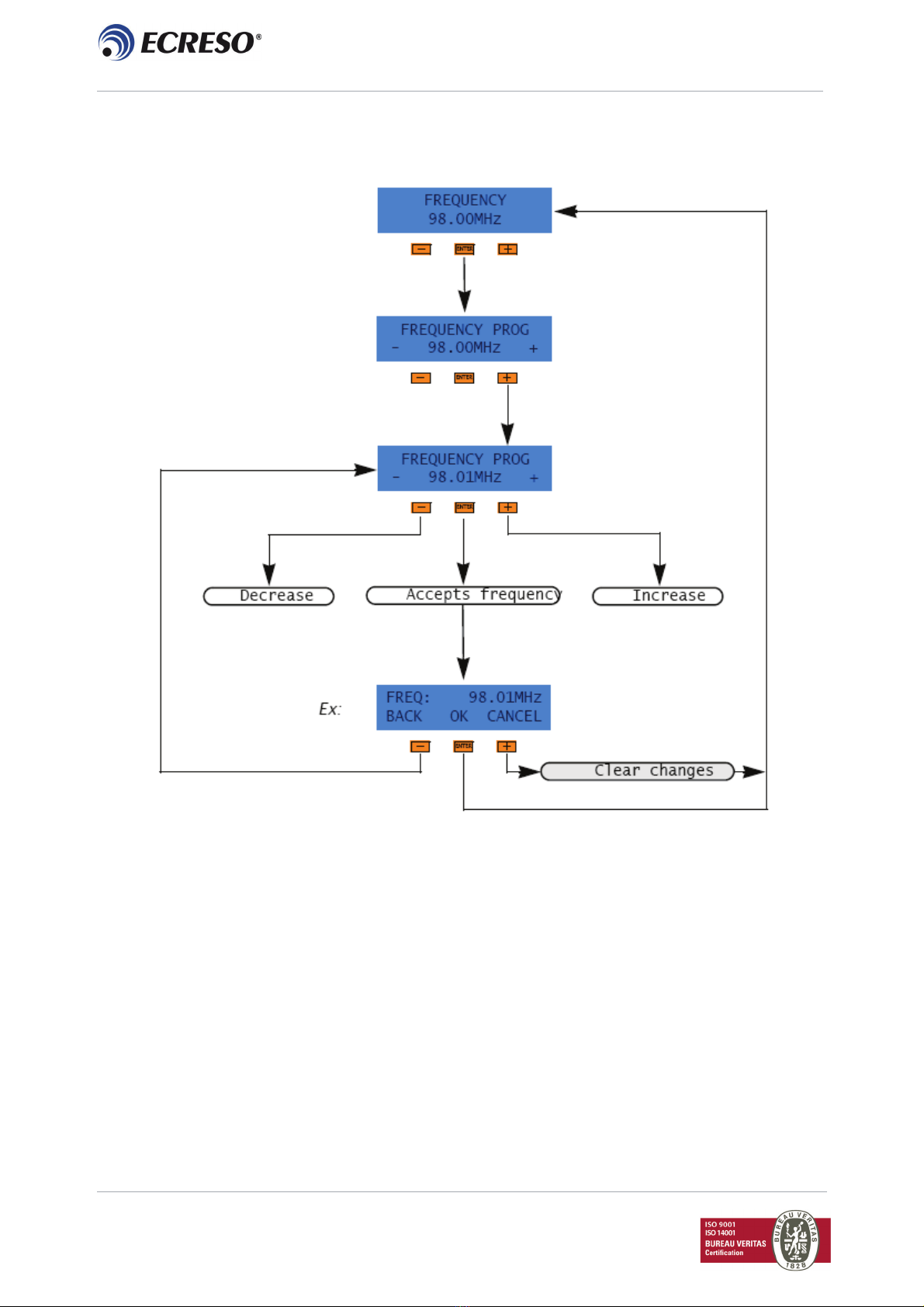
Helios Junior, User’s guide 02/2008
Transmission Frequency Settings menu
Page 20
ECRESO – 20, avenue Neil Armstrong – Parc d’Activites JF Kennedy – 33700 Bordeaux-Merignac – France
Table of contents
Other Ecreso Transmitter manuals


Popular Transmitter manuals by other brands


MTT
MTT MS3701F user manual

Evikon
Evikon PluraSens E2648-ETO user manual

Williams Sound
Williams Sound Hearing Helper T800 Specification sheet

Transmitter Solutions
Transmitter Solutions STINGER 2 manual

K-TEK
K-TEK MT5100 Installation & operation manual

Vestamatic
Vestamatic VestaFunk MS16 Series Installation and operating instructions


