Ecreso HELIOS FM 350 W User manual

ecreso WorldCast Systems Group
HELIOS FM 350 W
HELIOS FM 750 W
HELIOS FM 1000 W
HELIOS FM 1500 W
HELIOS FM 2000 W
USER MANUAL
87.5 –108 MHz
STEREO AND MULTIPLEX COMPACT FM DIGITAL TRANSMITTER
WITH TCP/IP MONITORING*
*depending on options
Date: 2012/08/28

Helios FM 350 W/750 W/1000 W/1500 W/2000 W, user manual–08/2012
Page 2
Head Office : Parc d’activites Kennedy - 20, avenue Neil Armstrong –F-33700 Bordeaux-Merignac (France)
TABLE OF CONTENTS
1. INTRODUCTION................................................................................................................................. 5
1.1. About Ecreso.............................................................................................................................. 5
1.2. Before you start.......................................................................................................................... 6
2. DESCRIPTION.................................................................................................................................... 7
2.1. General description.................................................................................................................... 7
2.2. Accessories................................................................................................................................ 7
2.3. Helios FM 350 W / 750 W / 1000 W / 1500 W / 2000 W Description......................................... 8
2.3.1. Front panel............................................................................................................................ 8
2.3.2. Rear panel............................................................................................................................. 9
2.3.3. Opened cover...................................................................................................................... 11
2.3.4. Synoptic............................................................................................................................... 13
2.3.5. 3U Rack............................................................................................................................... 14
2.4. Protecting the transmitter......................................................................................................... 14
2.4.1. Surge Protector................................................................................................................... 14
2.4.2. Protection against VSWR.................................................................................................... 15
2.4.3. Protection against high temperature................................................................................... 15
2.4.4. Protections incorporated into the PSU................................................................................ 15
3. TECHNICAL SPECIFICATIONS....................................................................................................... 16
3.1. RF section................................................................................................................................ 16
3.2. Composite operation................................................................................................................ 16
3.3. Stereo operation....................................................................................................................... 16
3.4. Mono operation ........................................................................................................................ 16
3.5. AF inputs .................................................................................................................................. 17
3.6. HF output.................................................................................................................................. 17
3.7. Power supply............................................................................................................................ 17
3.1. Interface panel.......................................................................................................................... 18
3.2. Environmental .......................................................................................................................... 18
3.3. Physical.................................................................................................................................... 18
3.4. Miscellaneous........................................................................................................................... 19
4. STARTING UP YOUR TRANSMITTER............................................................................................ 20
4.1. Connecting the transmitter....................................................................................................... 20
4.2. Using the front panel................................................................................................................ 21
4.2.1. Setting the transmitter......................................................................................................... 21
4.2.2. Input selection..................................................................................................................... 22
4.2.3. Setting the MPX inputs........................................................................................................ 23
4.2.4. MPX configuration............................................................................................................... 24
4.2.5. Setting the analog or AES inputs........................................................................................ 25
4.2.6. Getting on air....................................................................................................................... 25
4.3. Using the PC application.......................................................................................................... 26
4.3.1. Connecting with the control software application................................................................ 26
4.3.2. Setting the transmitter......................................................................................................... 26
4.3.3. Input selection..................................................................................................................... 26
4.3.4. Setting the MPX inputs........................................................................................................ 27
4.3.5. MPX configuration............................................................................................................... 27
4.3.6. Setting the analog or AES inputs........................................................................................ 27
4.3.7. Getting on air....................................................................................................................... 27
4.4. With the TCP/IP option............................................................................................................. 28
4.4.1. Network configuration ......................................................................................................... 28
4.4.2. Connecting to the web interface.......................................................................................... 28

Helios FM 350 W/750 W/1000 W/1500 W/2000 W, user manual–08/2012
Page 3
Head Office : Parc d’activites Kennedy - 20, avenue Neil Armstrong –F-33700 Bordeaux-Merignac (France)
5. FRONT SCREEN USE...................................................................................................................... 29
5.1. Overview................................................................................................................................... 29
5.2. Working principe....................................................................................................................... 29
5.3. Structure of the menus............................................................................................................. 31
5.3.1. Overview ............................................................................................................................. 31
5.3.2. First level measurements.................................................................................................... 32
5.3.3. First level menus................................................................................................................. 33
5.3.4. TX PARAMETERS Menu.................................................................................................... 34
5.3.5. ALARMS Menu.................................................................................................................... 34
5.3.6. INPUT SWITCH Menu........................................................................................................ 35
5.3.7. LINE1 Menu ........................................................................................................................ 36
5.3.8. MPX in Menu....................................................................................................................... 37
5.3.9. Audio Gene Menu............................................................................................................... 38
5.3.10.Modulation Menu................................................................................................................. 39
5.3.11.Stereo encoder Menu.......................................................................................................... 40
5.3.12.RDS / SCA encoder Menu.................................................................................................. 41
5.3.13.FM limiter Menu................................................................................................................... 42
5.3.14.RDS Menu........................................................................................................................... 43
5.3.15.Network Menu..................................................................................................................... 44
5.3.16.COM Menu.......................................................................................................................... 45
5.3.17.Power supply Menu............................................................................................................. 46
5.3.18.Temp/Fan Menu.................................................................................................................. 47
5.3.19.Time/Date Menu.................................................................................................................. 48
5.3.20.License Menu...................................................................................................................... 49
5.3.21.About / System Menu.......................................................................................................... 50
5.3.22.Easy/Expert Menu............................................................................................................... 51
5.3.23.Exit Menu ............................................................................................................................ 51
5.4. Main parameters description.................................................................................................... 52
5.4.1. TX PARAMETERS Menu.................................................................................................... 52
5.4.2. INPUT SWITCH Menu........................................................................................................ 52
5.4.3. Menu LINE 1 (ANA) ............................................................................................................ 53
5.4.4. LINE 2 Menu (AES)............................................................................................................. 54
5.4.5. MPX IN Menu...................................................................................................................... 54
5.4.6. PLAYER Menu.................................................................................................................... 55
5.4.7. AUDIO GENE Menu............................................................................................................ 55
5.4.8. MODULATION Menu.......................................................................................................... 56
5.4.9. STEREO ENCODER Menu ................................................................................................ 57
5.4.10.RDS / SCA ENCODER Menu............................................................................................. 57
5.4.11.FM LIMITER Menu.............................................................................................................. 58
5.4.12.RDS Menu........................................................................................................................... 58
6. SERIAL COMMANDS....................................................................................................................... 62
6.1. Working principle...................................................................................................................... 62
6.2. Serial commands...................................................................................................................... 63
6.2.1. System commands.............................................................................................................. 63
6.2.2. Measurement commands.................................................................................................... 64
6.2.3. Configuration commands.................................................................................................... 64
6.2.4. Alarm commands ................................................................................................................ 65
6.2.5. Input commands.................................................................................................................. 66
6.2.6. Encoder commands............................................................................................................ 68
6.2.7. RDS commands.................................................................................................................. 69
6.2.8. Transmitter commands ....................................................................................................... 70
6.2.9. Status commands ............................................................................................................... 71
6.2.10.Communication board commands ...................................................................................... 71
6.3. HyperTerminal connection ....................................................................................................... 72

Helios FM 350 W/750 W/1000 W/1500 W/2000 W, user manual–08/2012
Page 4
Head Office : Parc d’activites Kennedy - 20, avenue Neil Armstrong –F-33700 Bordeaux-Merignac (France)
7. CONFIGURATION WITH THE PC APPLICATION.......................................................................... 75
7.1. Overview................................................................................................................................... 75
7.2. Using the application................................................................................................................ 75
7.2.1. Connection.......................................................................................................................... 75
7.2.2. Configuration....................................................................................................................... 76
7.2.3. Saving parameters.............................................................................................................. 80
8. REMOTE CONTROL AND MONITORING WITH THE GPIO BOARD............................................ 81
8.1. Introduction............................................................................................................................... 81
8.2. Description of control and monitoring functions....................................................................... 81
8.3. Remote control function pinout ................................................................................................ 82
8.4. Remote monitoring function pinout .......................................................................................... 82
8.5. Physical representation of the GPIOs...................................................................................... 83
8.6. Management using serial commands ...................................................................................... 84
9. THE EMBEDDED WEBSITE ............................................................................................................ 86
9.1. Introduction............................................................................................................................... 86
9.2. Connecting to the embedded web site..................................................................................... 86
9.3. Viewing the Status.................................................................................................................... 87
9.4. Configuration............................................................................................................................ 88
9.5. System...................................................................................................................................... 89
9.5.1. Product ID ........................................................................................................................... 89
9.5.2. Date / Time.......................................................................................................................... 90
9.5.3. Users................................................................................................................................... 91
9.5.4. Network............................................................................................................................... 92
9.5.5. Support................................................................................................................................ 93
9.5.6. SNMP Agent........................................................................................................................ 94
9.5.7. Notifications......................................................................................................................... 96
9.5.8. Common traps..................................................................................................................... 97
9.5.9. IRT Traps ............................................................................................................................ 98
9.5.10.Ecreso Traps....................................................................................................................... 99
9.6. About........................................................................................................................................ 99
APPENDIX A: SOFTWARE OPTION MANAGEMENT...................................................................... 100
A.1. Using the front panel application.............................................................................................. 100
A.2. Using the PC application.......................................................................................................... 101
A.3. Using serial commands ............................................................................................................ 102
APPENDIX B: ADJUSTING THE IMPEDANCE OF ANALOG INPUTS............................................ 103
APPENDIX C: MAINTENANCE.......................................................................................................... 104
C.1. Changing the fuses................................................................................................................... 104
C.2. Changing the fan...................................................................................................................... 105
C.3. Changing the surge protector................................................................................................... 106
APPENDIX D: TROUBLESHOOTING................................................................................................ 107
D.1. Calibration ................................................................................................................................ 107
D.2. Complete Reset of the Helios FM ............................................................................................ 107
FOR MORE INFORMATION............................................................................................................... 108

Helios FM 350 W/750 W/1000 W/1500 W/2000 W, user manual–08/2012
Page 5
Head Office : Parc d’activites Kennedy - 20, avenue Neil Armstrong –F-33700 Bordeaux-Merignac (France)
1. INTRODUCTION
1.1. About Ecreso
Founded in 1956 near Bordeaux, ECRESO was created by radio broadcasting enthusiasts and counts today
as one of the most important players on the international broadcasting stage.
ECRESO offers analog and digital radio as well as digital TV transmitters (FM, DAB, DAB+, T-DMB, DVB-
T/H), low power transmitters, which are air-cooled, as well as high power devices either air or water-cooled.
ECRESO is part of the WorldCast Systems group of companies which combines the collective expertise &
extensive product portfolio of several major broadcast brands to offer turnkey systems in all major analog
and digital technologies. Other brands within the group include:
Audemat who designs monitoring equipment for analog and digital radio and TV as well as an
extensive range of facility remote control solutions.
APT Codecs who offer reliable and cost effective broadcast codec platforms delivering high quality
content over IP, T1, E1, ISDN & Leased Lines.
As such, WorldCast Systems can offer complete broadcast solutions for the delivery, transmission and
monitoring of broadcast content throughout the broadcast chain.
The group is founded on three core values:
1) Product innovation:
Audemat places a key emphasis on Research & Development and its innovative approach has been
repeatedly recognized by the industry. WorldCast Systems has won awards for innovation at
consecutive NAB Shows for over 10 years.
2) Customer satisfaction:
Audemat is dedicated to ensuring the best quality, value and service for its customers and has
achieved IS0 9001 certification.
3) Sustainable Development:
Audemat is committed to sustainable development and demonstrates this commitment in several
ways: it adheres to the UN Global Compact project and all new products are developed in keeping
with an eco-design philosophy and built within Audemat’s low energy consumption factory.
Audemat employs around 80 employees at headquarters in Bordeaux-Merignac, France. Audemat also has
a subsidiary in Miami, USA that manages the North & South American markets as well as sales offices in the
UK and India. An extensive network of international dealers and distributors means that the company is
represented in over 45 countries throughout Europe, Middle East, Africa and Asia.

Helios FM 350 W/750 W/1000 W/1500 W/2000 W, user manual–08/2012
Page 6
Head Office : Parc d’activites Kennedy - 20, avenue Neil Armstrong –F-33700 Bordeaux-Merignac (France)
1.2. Before you start
This equipment complies with international mechanical and electrical standards. To maintain this
compliance, as well as to ensure proper and safe working conditions and avoid electrical shocks and fire
hazards, you must comply with the following recommendations:
The device should only be utilized in the conditions described in the user manual.
The device is designed for industrial usage and must only be operated by qualified personnel.
The device may be heavy; it must be lifted and handled with care, specifically during unpacking and
set up.
Electrical precautions
Unplug from mains outlet before any intervention.
Any maintenance, adjustment or repair must be carried out by personnel specifically trained by
WorldCast Systems.
Before switching on the device, make sure the nominal voltage specified on the device matches the
mains nominal voltage.
The device should only be operated on a stable electrical network. If the electrical network is not
stable, a power conditioner, such as a UPS, must be used
The device must only be used with a plug that incorporates a protective ground contact.
To avoid any risk of electrocution, the protection conductor must not be cut, intentionally or
accidentally, either on the device or on the power cord.
High quality shielded cables are mandatory.
Environmental precautions
It is necessary to verify that environmental conditions comply with those recommended in the
manual.
Nothing must obstruct the ventilation.
To avoid any electromagnetic interference, the device must only be used when it is closed, installed
in a cabinet and connected to the earth as per the instructions.
The device should not be exposed to dripping or splashing and no objects filled with liquids, such as
coffee cups, should be placed on the equipment.
Connectors may be hot on high power units.
Precautions regarding the lithium battery
This device includes a lithium battery.
If the battery is not correctly replaced, there is a risk of explosion.
Only replace it with a battery of the same type. Contact us before attempting to use another type
Do not puncture the battery
Do not throw the battery in fire
Do not immerse the battery in water
Do not throw away the used battery, recycle it instead. You may send it back to us if needed.
If these precautions are not followed, the guarantee will be void.

Helios FM 350 W/750 W/1000 W/1500 W/2000 W, user manual–08/2012
Page 7
Head Office : Parc d’activites Kennedy - 20, avenue Neil Armstrong –F-33700 Bordeaux-Merignac (France)
2. DESCRIPTION
2.1. General description
Combining the very latest technologies with our proven RF experience, our 350 W, 750 W, 1000 W, 1500 W
and 2000 W transmitters have been designed to offer an innovative and highly reliable solution.
Among the first FM transmitters based on 6th Generation MOSFET, these transmitters are not only more
robust, they also deliver efficiency of up to 74%. Top signal quality and performance are achieved thanks to
the “FM Band Direct to Frequency” digital modulator which is at the heart of this range.
The manufacturing quality and the simplicity of use make these truly powerful transmitters to broadcast
analog FM programs.
The Helios FM 350 W, the Helios FM 750 W, the Helios FM 1000 W, the Helios FM 1500 W and the Helios
FM 2000 W are fully protected against overheating, VSWR and lightning.
In addition, several innovative features are available, such as RDS encoding and automated audio backup.
Fully featured for local maintenance and configuration, it also allows full remote control by Web server,
SNMP, RS232 or GPIOs*.
* Options available with the current version are:
Basic RDS: the internal RDS encoder makes it possible to manage basic RDS parameters (PI, PS,
TP, TA, PTY, MS, DI, radiotext, PTYN, group sequence, AF, 1 PSN, 2 DSN, dynamic scrolling PS)
GPIO: this additional board allows remote control and management of your transmitter.
TCP/IP: this additional board allows remote configuration via a web site and SNMP management
Please refer to Appendix A for more information on option management.
Project co-financed by the European Union, involved in the Aquitaine Area,
through the European Funds for local development.
2.2. Accessories
The Helios FM is supplied with:
1 power cable
1 serial cable
1 USB cable
4 10 A fuses (for Helios FM 350 W, 750 W and 1000 W only)
1 interlock plug
1 box including 1 CD (documentation + PC application) and 1 quick start notice.

Helios FM 350 W/750 W/1000 W/1500 W/2000 W, user manual–08/2012
Page 8
Head Office : Parc d’activites Kennedy - 20, avenue Neil Armstrong –F-33700 Bordeaux-Merignac (France)
2.3. Helios FM 350 W / 750 W / 1000 W / 1500 W / 2000 W Description
2.3.1. Front panel
Description of indicator LEDs:
CPU: blinks to indicate CPU activity
FAULT: major fault of the unit (RF / VSWR protection, Temperature, …)
WARNING: minor fault of the unit (ambient temperature, radiator temperature, fan, current, voltage,
loss of signal).
VSWR: VSWR of the unit
RF (3dB) : 3 dB of the unit
INTERLOCK: indicates that internal or external safety links are not activated
RF: indicates that the unit is on RF=ON. Associated to the RF button
LOCAL: indicates that the unit is in local mode. Associated to the Local button
RF monitoring output
Indicators: CPU, Fault,
Warning, RF (3 dB),
VSWR and Interlock
RS232 port
RF on/off and
local mode keys
and LEDs
LCD contrast
Navigation
keys
LCD display

Helios FM 350 W/750 W/1000 W/1500 W/2000 W, user manual–08/2012
Page 9
Head Office : Parc d’activites Kennedy - 20, avenue Neil Armstrong –F-33700 Bordeaux-Merignac (France)
2.3.2. Rear panel
Helios FM 350 W / 750 W / 1000 W
Helios FM 1500 W / 2000 W
Mains
7/16 RF output
Communication
board (option) *
Interlock
GPIO
(option)
Ground
MPX/SCA1
MPX/SCA2
19 kHz
Audio input Line1
(Ana or AES)
Audio input Line2
(Ana or AES)
Mains
7/16 RF output
Interlock
Ground
Communication
board *
N RF input
GPIO
(option)
MPX/SCA1
MPX/SCA2
19 kHz
Audio input Line1
(Ana or AES)
Audio input Line2
(Ana or AES)
Helios FM 350 W/750 W/1000 W/1500 W/2000 W, user manual–08/2012
Page 10
Head Office : Parc d’activites Kennedy - 20, avenue Neil Armstrong –F-33700 Bordeaux-Merignac (France)
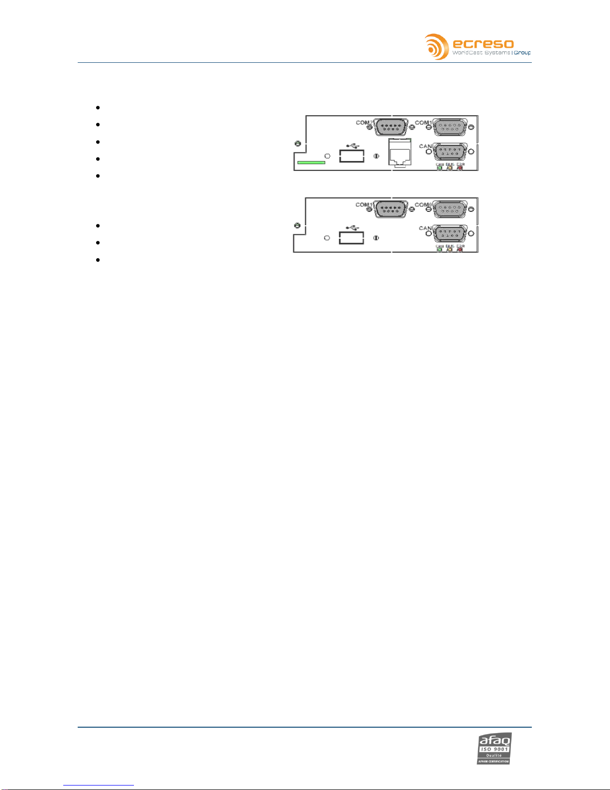
* Two optional communication boards are available:
TCP/IP board
2 RS232 ports (COM1 and COM2)
1 µSD card
1 USB port
1 Ethernet port
1 CAN port
CAN board
2 RS232 ports (COM0 and COM1)
1 slave USB port
1 CAN port
On the CAN board, the COM0 port is reserved for the unit’s upgrade.
Please not that the 19 kHz output and the 10 MHz input are not enabled on this preliminary version.

Helios FM 350 W/750 W/1000 W/1500 W/2000 W, user manual–08/2012
Page 11
Head Office : Parc d’activites Kennedy - 20, avenue Neil Armstrong –F-33700 Bordeaux-Merignac (France)
2.3.3. Opened cover
Helios FM 350 W / 750 W / 1000 W
High output
power supply
Output filter
Power bloc
Fans
LCD display
on control/display board
Surge protector
GPIO board
Communication
board
RF amplifier bloc
RF output
detection
Control board
Mains filter
RF input board
Digital modulator
Audio inputs

Helios FM 350 W/750 W/1000 W/1500 W/2000 W, user manual–08/2012
Page 12
Head Office : Parc d’activites Kennedy - 20, avenue Neil Armstrong –F-33700 Bordeaux-Merignac (France)
Helios FM 1500 W / 2000 W
High output
power supply
Output filters
LCD display
on control/display board
RF output
detection
Control board
Communication
board
Output
combiner
RF amplifier
blocs
RF input
board
Input
splitter
Fans
Power bloc
Digital modulator

Helios FM 350 W/750 W/1000 W/1500 W/2000 W, user manual–08/2012
Page 13
Head Office : Parc d’activites Kennedy - 20, avenue Neil Armstrong –F-33700 Bordeaux-Merignac (France)
2.3.4. Synoptic
Helios FM 350 W / 750 W / 1000 W
Helios FM 1500 W / 2000 W

Helios FM 350 W/750 W/1000 W/1500 W/2000 W, user manual–08/2012
Page 14
Head Office : Parc d’activites Kennedy - 20, avenue Neil Armstrong –F-33700 Bordeaux-Merignac (France)
Audio
2.3.5. 3U Rack
The choice of stainless steel as material guarantees against corrosion. The rack structure and the structure
of the monoblock front panel reinforce the device. The rectangular outline of the front panel has an LCD
display. The transport handles are mechanically interchangeable and can be removed. The cover is fixed by
a set of M3 POZIDRIV screws and can be easily removed. The user has access to every module to set the
parameters of the device.
2.4. Protecting the transmitter
To ensure the transmitter will work with no risk of damage, a series of protections have been set.
2.4.1. Surge Protector
An optional surge protector module can be added to the chassis. The goal of this module is to limit the surge
caused by lightning. It works after the main protector usually located in the electrical board and before the
power supply protector, thus offering an optimal level of protection. The protector principle is to capture the
surge and divert it to the ground so as to protect the transmitter and its power supplies.
The surge protector used by Ecreso includes multi-MOV technology and a gas discharge tube (GDT) giving
a very high protection and very low parasitic capacitance and leakage currents.
Please refer to Appendix B ‘Maintenance’ for the procedure to replace the surge protection module.
G1
D1
AES1
G2
D2
AES2
MPX
SCA
Audio 1
Audio 2
Internal player
19 kHz output

Helios FM 350 W/750 W/1000 W/1500 W/2000 W, user manual–08/2012
Page 15
Head Office : Parc d’activites Kennedy - 20, avenue Neil Armstrong –F-33700 Bordeaux-Merignac (France)
2.4.2. Protection against VSWR
Several systems coexist to offer the optimal protection against VSWR:
Hardware protection:
In case of open circuit or short-circuit, the RF is cut. When the situation returns to normal, it is
automatically reset.
Software protection:
The reflected power is limited to 3 W for Helios FM 20 W, to 10 W for Helios FM 100 W, to 40 W for
Helios FM 350 W / 750 W / 1000 W and to 80 W for Helios FM 1500 W / 2000 W
Software settings for the reflected power security management (see VSWR Trip, section 5.4.1).
2.4.3. Protection against high temperature
The Power Supply module includes its own protector against high temperature: the protector cuts off the
power supply output voltage if the temperature is abnormally high. When the situation returns to normal, it is
automatically reset. The temperature threshold value varies depending on the PSU.
The ambient temperature and the radiator temperature are monitored.
The max ambient temperature is set by software (see menu Temp/Fan, section 5.3.18), default value
is 50°C. In case of overshoot, a Warning alarm is triggered (Alarm Amb).
The max radiator temperature is set by serial command (see serial command CONF.HEAT.MAX,
section 6.2.3), default value is 65°C. In case of overshoot, a Warning alarm is triggered (Alarm
Heat).
The max internal temperature is set at 70°C. If the temperature exceeds 70°C, the RF is cut off and
a fault alarm is triggered (Alarm Temp).
2.4.4. Protections incorporated into the PSU
The main power supply voltage and the auxiliary power supply voltage are monitored as follows:
Main power supply:
if the difference between the measured voltage and the expected voltage is greater than 10%, a
Warning alarm is triggered (Alarm Volt1). Expected voltage is automatically computed.
Auxiliary power supply:
Voltage should be either 5, 12 or -12 V. if the difference between the measured voltage and the
nominal voltage is greater than 10%, a Warning alarm is triggered (Alarm Volt Aux).
The amperage is also measured. The threshold varies depending of the power of the Helios FM: 2 A for the
Helios FM 20 W, 8.5 A for the Helios FM 100 W, 20 A for the Helios FM 350 W, 23 A for the Helios FM 750
W, 29 A for the Helios FM 1000 W, 26 A per amplifier pallet for the Helios FM 1500 W, 31 A per amplifier
pallet for the Helios FM 2000 W. In case of overshoot, a Warning alarm is triggered (Alarm Cur) and the
nominal power is reduced.

Helios FM 350 W/750 W/1000 W/1500 W/2000 W, user manual–08/2012
Page 16
Head Office : Parc d’activites Kennedy - 20, avenue Neil Armstrong –F-33700 Bordeaux-Merignac (France)
3. TECHNICAL SPECIFICATIONS
3.1. RF section
Frequency range 87.5 to 108 MHz
Summary of different steps 10 kHz
Frequency stability < 10-6 per year
Power range 50-350 W, 50-750 W, 50-1000 W, 150-1500 W or 200-2000 W @
ROS=1.35
Power output continuously 50-350 W, 50-750 W, 50-1000 W, 150-1500 W or
200-2000 W
Spurious and harmonic suppression > 75 dBc
3.2. Composite operation
Bandwidth > 40 Hz to 53 kHz @ 0.1 dB
> 20 Hz to 60 kHz @ 0.2 dB
> 60 kHz to 80 kHz @ 0.4 dB
Intermodulation distortion < 0.05%
FM S/N ratio > 80 dB RMS @ 75 kHz deviation
AM noise < 0.1% (50 dB) RMS (20-20 000 Hz)
3.3. Stereo operation
Bandwidth > 20 Hz to 15 kHz @ 0.1 dB
38 kHz discontinuance > 50 dB
Stereophonic crosstalk > 50 dB
Preemphasis 0 µs, 50 µs or 75 µs
3.4. Mono operation
Bandwidth > 40 Hz to 15 kHz @ 0.1 dB
Out of band rejection > 40 dB @ 19 kHz
Preemphasis 0 µs, 50 µs or 75 µs

Helios FM 350 W/750 W/1000 W/1500 W/2000 W, user manual–08/2012
Page 17
Head Office : Parc d’activites Kennedy - 20, avenue Neil Armstrong –F-33700 Bordeaux-Merignac (France)
3.5. AF inputs
Analog (LINE1)
Connector "XLR" type
Impedance > 10 kΩby default, adjustable to 600 Ωby jumpers, balanced
Bandwidth Software adjustable
Level Software adjustable (-18/+18 dBu range)
AES (LINE2)
Connector "XLR" type
Impedance > 110 Ωbalanced
Bandwidth Software adjustable
Level Software adjustable (-20 to 0 dBFS range)
Sampling rate Auto adjusted up to 192 kb/s
Bit 16, 24, 32
Multiplex (MPX/SCA)
Connector "BNC" type
Impedance > 5 kΩunbalanced
Level Software adjustable (-18/+18 dBu range)
3.6. HF output
Connector 7/16 type
Impedance 50 Ω
Monitoring (RF Monitor)
Level
Helios FM 350 W / 750 W / 1000 W 10 dBm 3 dB @ 750 W at main output
Helios FM 1500 W / 2000 W 10 dBm 3 dB @ 1500 W at main output
Slope 20 x Log (F/98)
Directivity >20 dB in the band
3.7. Power supply
Voltage 184 VAC to 264 VAC
Frequency 47 Hz - 63 Hz
Max consumption 550 W @ nominal power (350 W version)
1150 W @ nominal power (750 W version)
1550 W @ nominal power (1000 W version)
2300 W @ nominal power (1500 W version)
3050 W @ nominal power (2000 W version)
Fuses (for Helios FM 350 W / 750W / 1000 W) 10 AT

Helios FM 350 W/750 W/1000 W/1500 W/2000 W, user manual–08/2012
Page 18
Head Office : Parc d’activites Kennedy - 20, avenue Neil Armstrong –F-33700 Bordeaux-Merignac (France)
3.1. Interface panel
Indicators Green CPU LED: CPU activity
Red FAULT LED: major fault
Yellow WARNING LED: minor fault
Red RF (3 dB) LED: RF fault (3 dB)
Red VSWR LED: VSWR fault
Green INTERLOCK LED: safety interlock
Green RF LED: RF on
Orange LOCAL LED: local mode
Screens Back lighted LCD: displays operating parameters and menus.
Buttons RF, local, +, -- and OK
3.2. Environmental
Nominal operating temperature 5°C to 45°C
Maximum operating temperature 0°C to 50°C
Warehousing temperature -20°C to +70°C
Warehousing time < 10 years
Cooling Internal ventilation
Helios FM 350 W: ~20 I/s
Helios FM 750 W: ~20 I/s
Helios FM 1000 W: ~20 I/s
Helios FM 1500 W: ~55 l/s
Helios FM 2000 W: ~55 l/s
3.3. Physical
Helios FM 350 W / 750 W / 1000 W
Overall dimension 19’’ (482.6 mm) X 3U (133.5 mm) X 470 mm
Rack size without front panel 440.4 X 126.2 X 432 mm (WxHxD)
Enclosure depth required 600 mm
Mounting 19’’enclosure, with 4 M6X12 screws
Weight around 13 kg
Helios FM 1500 W / 2000 W
Overall dimension 19’’ (482.6 mm) X 3U (133.5 mm) X 690 mm
Rack size without front panel 440.4 X 126.2 X 620 mm (WxHxD)
Enclosure depth required 700 mm
Mounting 19’’enclosure, with 4 M6X12 screws
Weight around 18 kg

Helios FM 350 W/750 W/1000 W/1500 W/2000 W, user manual–08/2012
Page 19
Head Office : Parc d’activites Kennedy - 20, avenue Neil Armstrong –F-33700 Bordeaux-Merignac (France)
3.4. Miscellaneous
Marking CE
Standards 1999/5/CE (R&TTE)
ETS 302 018 (EMC)
ETS 300 384 (Radio)
NF EN 60215 (Safety)

Helios FM 350 W/750 W/1000 W/1500 W/2000 W, user manual–08/2012
Page 20
Head Office : Parc d’activites Kennedy - 20, avenue Neil Armstrong –F-33700 Bordeaux-Merignac (France)
4. STARTING UP YOUR TRANSMITTER
4.1. Connecting the transmitter
1. Make sure the interlock plug is present on the rear panel
2. Connect the transmitter RF output to a 50 load with a wattmeter.
3. The 50 charge power must be greater than 500 W for a 350 W transmitter, greater than 1000 W for a
750 W transmitter, greater than 1250 for a 1000 W transmitter, greater than 1875 W for a 1500 W
transmitter and greater than 2500 W for a 2000 W transmitter.
When you acquired your transmitter, the RF amplifier is deactivated and power is set to 0 W. These
settings can be adjusted using the PC application, the front panel application or serial commands.
4. Connect the audio or MPX inputs.
5. To use the PC application or the serial commands, connect a PC to the serial port on the front panel of
the Helios.
If your PC does not have a RS-232 port, use a USB/RS-232 cable.
6. Connect to power using the provided cable; you may unscrew the cable loop and pass the power cable
through it to secure it.
7. Press the Local button on the front panel, then the RF button.
To configure the transmitter using the front panel: see section 4.2.
To configure the transmitter using the PC application: see section 4.3.
To set network parameters (TCP/IO option only): see section 4.4.
To use serial commands, see section 6.
2
3
5
6
1
4
2
3
5
1
Rear panel
Helios FM 350 W / 750 W / 1000 W
Rear panel Helios 1500 W / 2000 W
Front panel all versions
This manual suits for next models
4
Table of contents
Other Ecreso Transmitter manuals


Popular Transmitter manuals by other brands


Alligator
Alligator KC-9512 instruction manual

AMG
AMG AMG3743E instruction manual

Metek
Metek RCT 10 series Installation and operating instruction

Akerstroms
Akerstroms REMOTUS BC7400 DRIVING INSTRUCTION

Endress+Hauser
Endress+Hauser Deltabar M PMD55 Brief operating instructions

Vega
Vega VEGABAR 82 operating instructions


