MT5100-0200-1 Rev b (2-2013) DCN0365 2
MT5100
Guided Wave Radar Level and Interface Transmitter
TABLE OF CONTENTS
1. Introduction ............................................................................................................................................................4
2. Overview ................................................................................................................................................................5
2.1 Storage and Handling Information.................................................................................................................5
2.2 Ambient Temperature....................................................................................................................................5
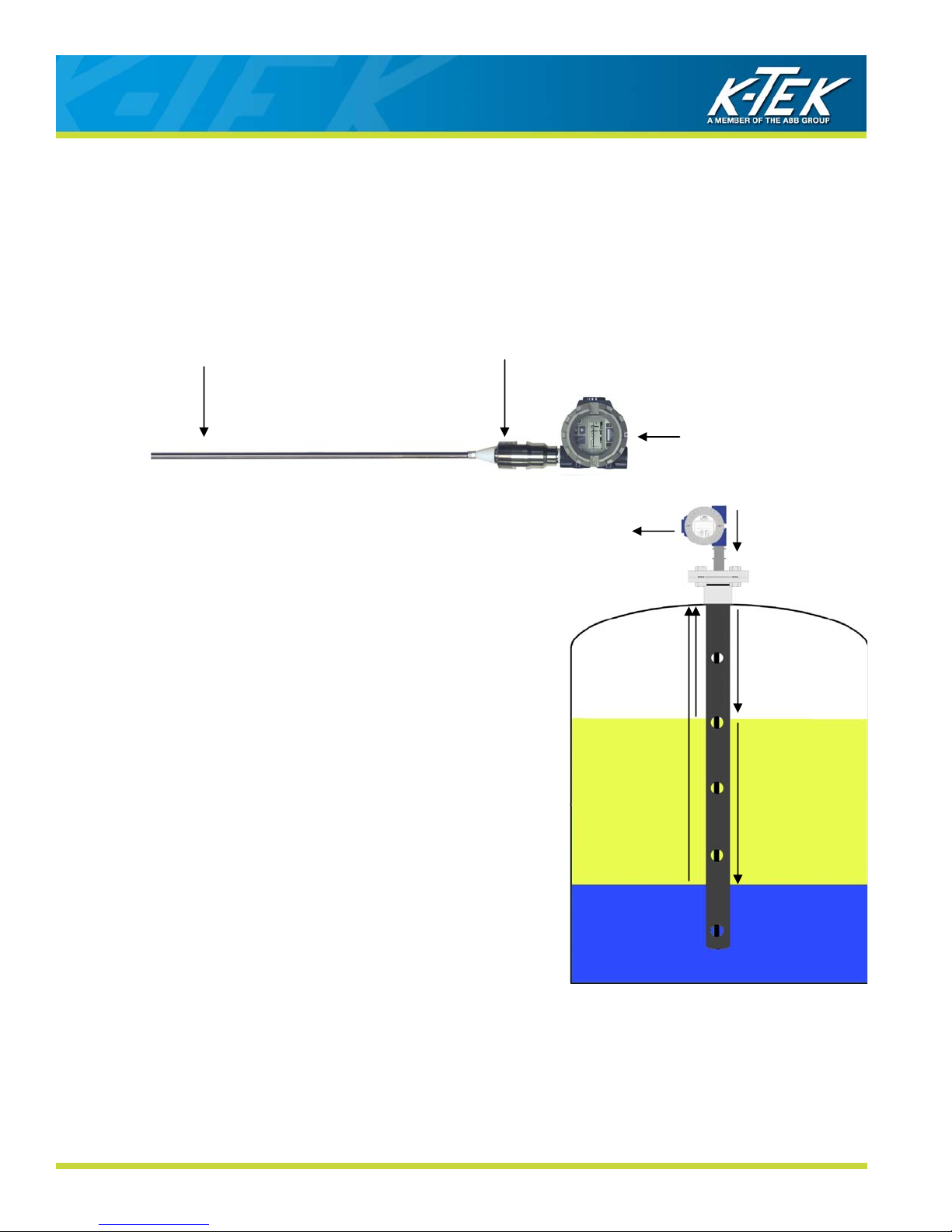
2.3 Description and Principle of Operation..........................................................................................................6
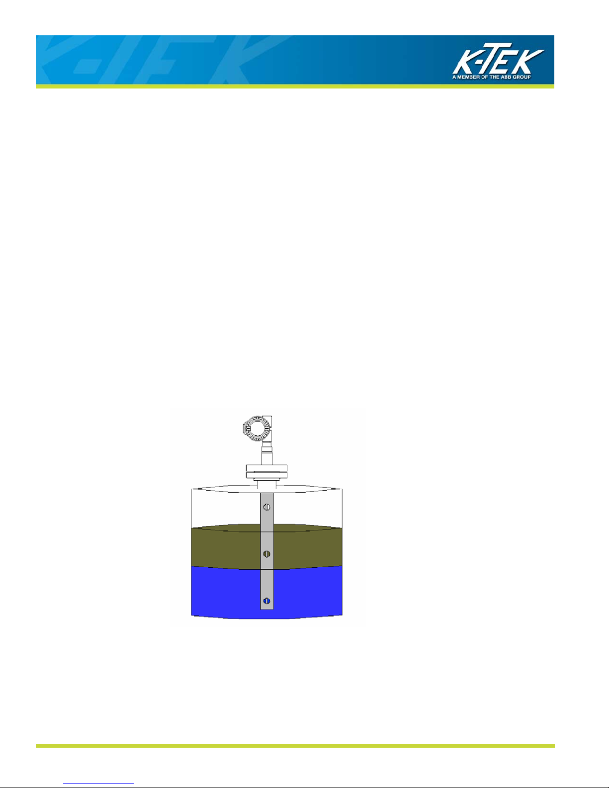
2.4 Total Level and Interface Level Measurement ..............................................................................................7
3. Installation ..............................................................................................................................................................8
3.1 Special Requirements ...................................................................................................................................8
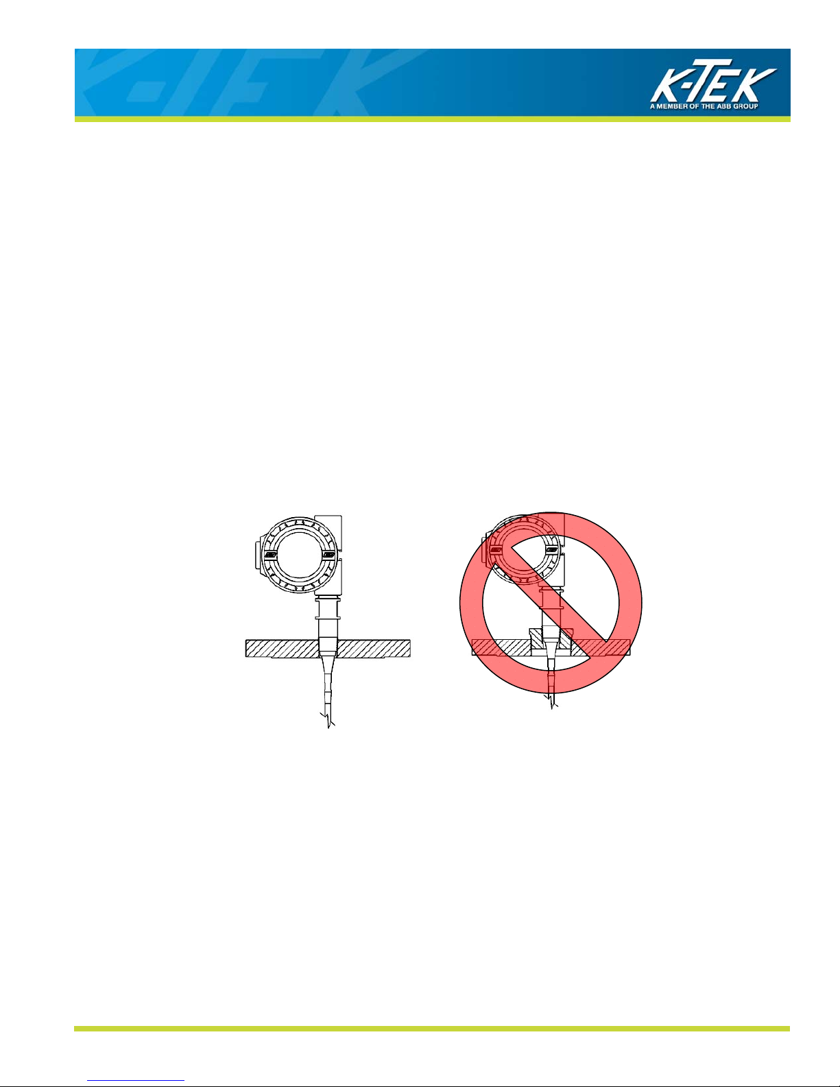
3.2 Mechanical Installation ..................................................................................................................................9
3.2.1 Shortening of the Probe .....................................................................................................................9
3.2.2 Plastic Tanks, Fiberglass Tanks, and Open Air Installations .............................................................9
3.2.3 Single Probes in Stilling Wells............................................................................................................10
3.2.4 Single Probes in External Chambers .................................................................................................12
3.2.5 Dual Rod/Cable Probes......................................................................................................................13
3.2.6 Coaxial Probes ...................................................................................................................................13
3.2.7 Unmeasurable Zones .........................................................................................................................14
3.3 Shortening of Probes.....................................................................................................................................15
3.4 Electrical Installation......................................................................................................................................15
4. Commissioning.......................................................................................................................................................16
4.1 Display Operation..........................................................................................................................................16
4.1.1 Jumper Settings .................................................................................................................................17
4.1.2 Push Buttons ......................................................................................................................................17
4.2 MT5100 Menu Flow Chart.............................................................................................................................18
4.3 Basic Setup ...................................................................................................................................................19
4.3.1 Units ...................................................................................................................................................19
4.3.2 Probe Type.........................................................................................................................................19
4.3.3 Probe Length......................................................................................................................................20
4.3.4 Offsets ................................................................................................................................................21
4.3.5 Upper Dielectric..................................................................................................................................22
4.3.6 Actual Interface ..................................................................................................................................22
4.3.7 Lower Dielectric (Optional) .................................................................................................................22
4.3.8 Language............................................................................................................................................23
4.4 Quick Calibration ...........................................................................................................................................23
4.5 mA Output Setup ...........................................................................................................................................24
4.5.1 Output.................................................................................................................................................24
4.5.2 LRV 4mA ............................................................................................................................................24
4.5.3 URV 20mA..........................................................................................................................................25
4.5.4 Dampening .........................................................................................................................................25
4.5.5 Alarm Delay........................................................................................................................................26
4.5.6 DAC Trim............................................................................................................................................26
4.5.7 LOOP Test..........................................................................................................................................26
4.5.8 HART Address ...................................................................................................................................27
4.6 Extended Setup.............................................................................................................................................27
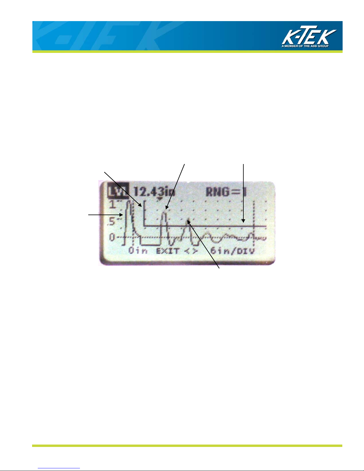
4.6.1 Waveform Display ..............................................................................................................................28
4.6.2 Functions ............................................................................................................................................30
4.6.3 Temperature.......................................................................................................................................31
4.6.4 Flooded Chamber...............................................................................................................................31
4.6.5 Flooded Total .....................................................................................................................................31
4.6.6 Linearization Menu .............................................................................................................................32
4.6.6.1 Linearization for Measurement.............................................................................................33
4.6.6.2 Linearization for Volume ......................................................................................................34
4.6.6.3 Linearization for Flow ...........................................................................................................35
4.6.6.4 User Functions .....................................................................................................................36
4.7 Secondary Output - RI100 Option .................................................................................................................36