7
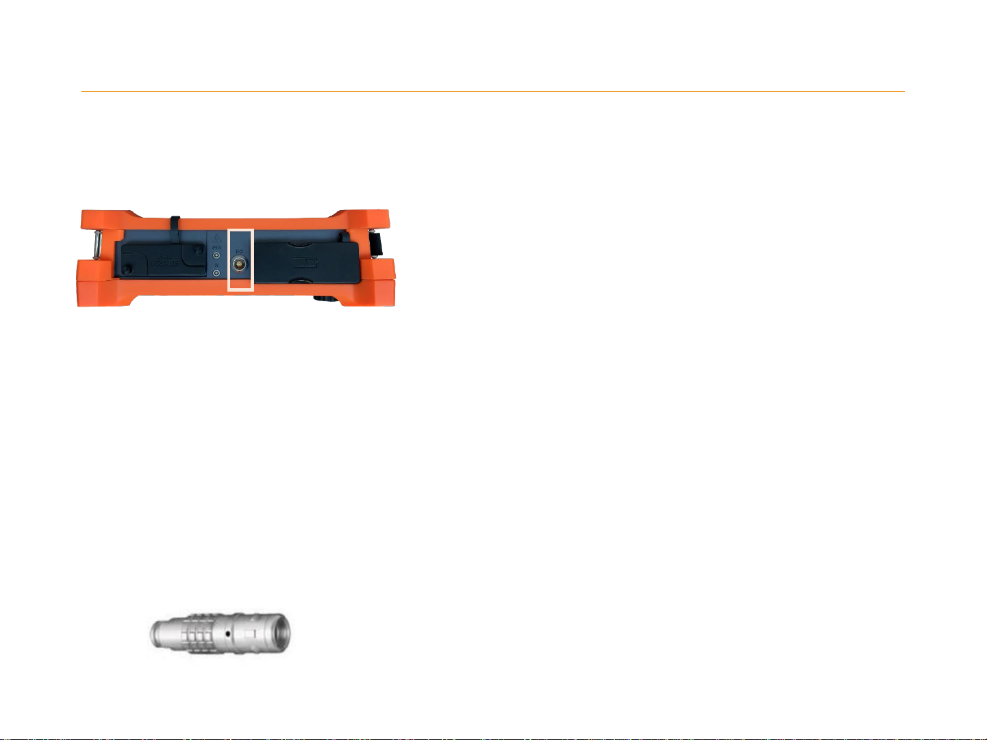
Connector Location
•On MANTIS system, There are one UT channel that can be used:
•1- Separated transmitter/receiver mode.
•P/R: transmitters
•R: Receiver
•2- Connected transmitter/receiver mode.
•P/R: transmitters / Receiver
•R: not connected
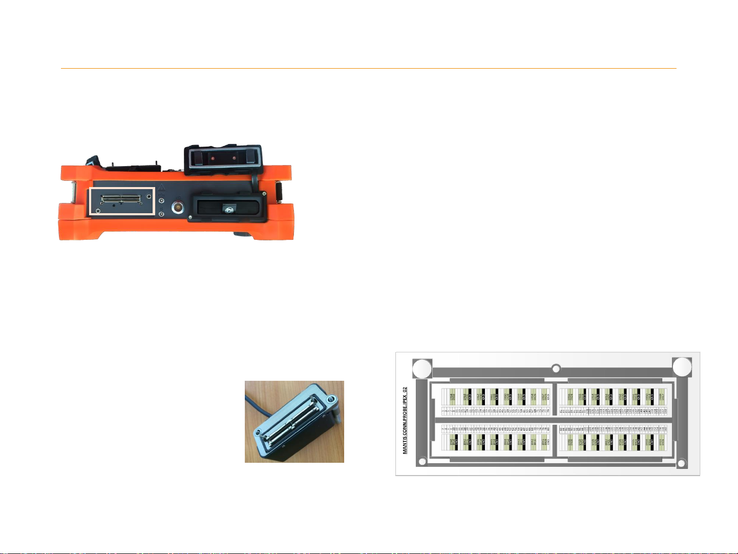
Connector Utility
Connector Mapping
Connector Information
Supplier: LEMO
Reference: ERN.00.250.CTL
Matching Connector
Our U.T connector is NimCAMAC standard. Many
supplier can provide matching connector.
We advice you to use one of this two :
Supplier: LEMO
Reference: FGG.00.302.CLAD35
3. MANTIS_UT CONNECTOR
For electric safety reasons, only accessories approved
by EDDYFI can be used with our system. Before
purchasing any probe, please contact us.