eddyfi TriTrax 200 User manual
Eddyfi Robotics Inc.
2569 Kenworth Road, Suite C
Nanaimo, BC, V9T 3M4
CANADA
+1.250.729.8080
info@eddyfitechnologies.com
www.eddyfitechnologies.com
TriTrax™ 200
Vertical Crawler Inspection Vehicle

TriTrax™ 200 Vertical Crawler
Document: UMDT017749.docm
Revision: A02
Created by: JS
Date: 13 Apr 2021
IPN: 3094329-A02
Source Location: C:\ePDM\ISLEng\Products\DT-VersaTrax100MkII\Manuals\UMDT017749.docm
Page 2 of 36
User Manual
Table of Contents
About This Manual........................................................................................................................................4
Description ....................................................................................................................................................4
Specifications............................................................................................................................................5
Precautions...............................................................................................................................................5
Certification...............................................................................................................................................6
Safety........................................................................................................................................................6
Intended Use.............................................................................................................................................7
System Setup................................................................................................................................................8
Personnel Requirements..........................................................................................................................8
Working and Storage Environment...........................................................................................................8
System Power.........................................................................................................................................10
Power Requirements ...........................................................................................................................10
Generators / Inverters..........................................................................................................................10
ICON™ Portable Controller....................................................................................................................10
Interface Box Connection .......................................................................................................................10
Vehicle and Tether Connection ..............................................................................................................11
Portable Reel Setup................................................................................................................................13
Mini-Reel Setup ......................................................................................................................................14
Tether Handling ......................................................................................................................................15
Connector Handling................................................................................................................................15
SubConn Connector: Lubrication and Cleaning ..................................................................................16
Impulse Connector: Lubrication and Cleaning.....................................................................................16
Vehicle Configuration..................................................................................................................................17
Front Camera Removal / Installation......................................................................................................17
Size Configuration ..................................................................................................................................18
Operation.....................................................................................................................................................23

TriTrax™ 200 Vertical Crawler
Document: UMDT017749.docm
Revision: A02
Created by: JS
Date: 13 Apr 2021
IPN: 3094329-A02
Source Location: C:\ePDM\ISLEng\Products\DT-VersaTrax100MkII\Manuals\UMDT017749.docm
Page 3 of 36
User Manual
Pre-Operations Check ............................................................................................................................23
Post-Operations Check...........................................................................................................................24
ICON™ Software ....................................................................................................................................25
ICON™ Control Panel..........................................................................................................................25
Three-Track Operation ...........................................................................................................................25
Vertical Crawler Expand & Contact Force..............................................................................................26
Dealing with Obstacles ...........................................................................................................................27
Inspection Guidelines .............................................................................................................................28
Vehicle Recovery....................................................................................................................................28
Troubleshooting......................................................................................................................................29
Camera Control Problems ...................................................................................................................29
Video Problems....................................................................................................................................29
Vehicle Problems.................................................................................................................................30
Reel Problems .....................................................................................................................................30
Maintenance................................................................................................................................................31
Galvanic Corrosion Control.....................................................................................................................31
Rinsing and Cleaning..............................................................................................................................32
Microtrac™ Maintenance........................................................................................................................32
Camera Maintenance .............................................................................................................................32
Tether Re-termination.............................................................................................................................32
Diameter and Force Feedback Calibration.............................................................................................33
Diameter Feedback Calibration ...........................................................................................................33
Force Feedback Calibration.................................................................................................................34
Parts and Repairs .......................................................................................................................................35
Ordering Parts/Customer Service...........................................................................................................35
Warranty Repairs ........................................................................................................................................36
Factory Returns to Canada.....................................................................................................................36
Product/System Drawing Package Availability.......................................................................................36

TriTrax™ 200 Vertical Crawler
Document: UMDT017749.docm
Revision: A02
Created by: JS
Date: 13 Apr 2021
IPN: 3094329-A02
Source Location: C:\ePDM\ISLEng\Products\DT-VersaTrax100MkII\Manuals\UMDT017749.docm
Page 4 of 36
User Manual
Limited Warranty Policy..........................................................................................................................36
About This Manual
This manual has been prepared to assist you in the operation and maintenance of your Eddyfi Technologies
equipment. Correct and prudent operation rests with the operator who must thoroughly understand the
operation, maintenance, service and job requirements. The specifications and information in this manual
are current at the time of printing.
This product is continually being updated and improved. Therefore, this manual endeavor to explain and
define the functionality of the product. Furthermore, schematics or pictorials and detailed functionality may
differ slightly from what is described in this manual.
Eddyfi Technologies reserves the right to change and/or amend these specifications at any time without
notice. Information in this manual does not necessarily replace specific regulations, codes, standards, or
requirements of others such as government or site regulations.
This manual is copyright © 2021 by Eddyfi Robotics Inc. All rights reserved.
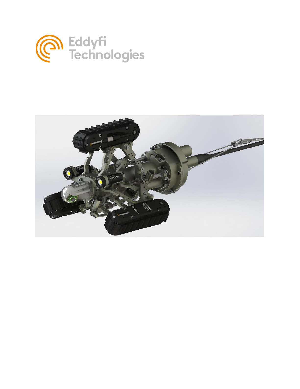
Description
The TriTrax™ 200 Vertical Crawler system is a Microtrac™ 4000 based vehicle used for navigating pipes of
200 –400 mm (8 –16 in) internal diameter with the camera centered. The crawler can travel vertically in the
pipe up or down.
The inspection system has been manufactured with the hazards and demands of pipe inspection in mind. A
minimized vehicle profile provides maximum clearance for passage of service intrusions in the pipe. The
vehicle employs marine technology for underwater operation down to a depth of 30 m (100 ft).
The TriTrax™ 200 can also be used in dry environments. The rugged design ensures a long service life and
helps protect the vehicle from damage during normal use.

TriTrax™ 200 Vertical Crawler
Document: UMDT017749.docm
Revision: A02
Created by: JS
Date: 13 Apr 2021
IPN: 3094329-A02
Source Location: C:\ePDM\ISLEng\Products\DT-VersaTrax100MkII\Manuals\UMDT017749.docm
Page 5 of 36
User Manual
Specifications
Minimum Vehicle
Dimensions
Base Configuration: No Spacers
Ø200 mm x 425 mm Long (8 x 16.7 in)
Vehicle Weight1
Base Configuration
8.5 kg (19 lb)
Depth Rating
30 m (100 ft)
Pipe Size
Range2
Base Configuration: No Spacers
Ø203mm to Ø305mm (8” to 12”) pipe
Extension 50mm (2 inch) spacers
Ø305mm to Ø405mm (12” to 16”) pipe
Extension 75mm (3 inch) spacers
Ø355mm to Ø455mm (14” to 18”) pipe
Min Bend
Radius3
8-Inch Pipe
610mm (24 in) Radius IN 200 mm (8 in) pipe
12-Inch Pipe
460mm (18 in) Radius IN 305 mm (12 in) pipe
Maximum Tether Length4
300 m (1,000 ft)
Tracks
3x Microtracs™4000
Camera
Front
Spectrum™45 Pan & Tilt
Rear
Onyx™
Lights
2x 801 Lights
Reel
Optional portable tether reel with payout encoder
Power Requirements
100 –240 VAC 50/60Hz, 5A
Operating Temperature
0 –40 ºC (32 –122 ºF)
Storage Temperature
-20° –60 ºC (-4 –140 ºF)
1
Weights may vary depending on optional components
2Specified pipe sizes are internal diameters
3Using 10-pin Connector. In general, as pipe size increases Min Bend Radius decreases
4Actual travel distance may be decreased depending on inspection geometry (traction and number of bends)
Precautions
IMPORTANT: When configuring a 70V system, check to see if the tracks are compatible. Older
versions of 4000 series Microtracs™ are not 70V compatible. Look for the Wide Input Voltage
symbol \V/ located on the side plate of the track indicating 70V compatibility.

TriTrax™ 200 Vertical Crawler
Document: UMDT017749.docm
Revision: A02
Created by: JS
Date: 13 Apr 2021
IPN: 3094329-A02
Source Location: C:\ePDM\ISLEng\Products\DT-VersaTrax100MkII\Manuals\UMDT017749.docm
Page 6 of 36
User Manual
Certification
The TriTrax™ 200 system is built in accordance with the Low Voltage Directive 2014/35/EU, Machinery
Directive 2006/42/EC, and Electromagnetic Compatibility Directive 2014/30/EU.
Safety
To use this product properly and safely, every user must first read these operating instructions and observe
the safety instructions contained therein. Take care of these operating instructions and keep them in a place
where they can be accessed by everyone. Untrained personnel should not handle or operate this equip-
ment.
CAUTION: Failure to follow these safety instructions may result in injury or equip-
ment damage.
WARNING: Hazardous Voltage 36-70 VDC. Do not power the vehicle from any
source other than an Eddyfi controller intended for that vehicle.
WARNING: Intense Optical Radiation - The Spectrum camera lights, and 801
lights are extremely bright. Never look directly at the lights. Use a welding filter
(shade #8 or higher) if inspecting the LEDs.
•When performing maintenance or functional checks of the camera lights, take precautions to pro-
tect nearby personnel from unintended exposure which could be temporarily blinding.
•Observe safe lifting practices. For storage and shipping, the TriTrax™ 200 system is packed in
three parts: Controller, Vehicle and Tether. Each of the three components is either built or packed
into a Pelican case with carrying handle. The heaviest case containing the tether and mini reel is
equipped with wheels and extending handle like a suitcase.
•Do not operate the system with damaged wires. A short circuit may damage the power system,
telemetry system, cameras, or attached equipment. Exposed wires may also create a shock haz-
ard.
•Disconnect the power source before servicing the product; otherwise, damage may result.
•Although designed for durability, the vehicle and its components or attached devices may suffer
structural damage if dropped or impacted. A lifeline or fall arrest system should be used at all time
when the vehicle is navigating on a vertical or inverted horizontal position. In addition, stepping on
the tether may pull the vehicle off the wall causing it to fall and sustain physical damage.
TriTrax™ 200 Vertical Crawler
Document: UMDT017749.docm
Revision: A02
Created by: JS
Date: 13 Apr 2021
IPN: 3094329-A02
Source Location: C:\ePDM\ISLEng\Products\DT-VersaTrax100MkII\Manuals\UMDT017749.docm
Page 7 of 36
User Manual
•All personnel operating or maintaining this equipment must be trained and competent.
•Eddyfi equipment is used in many varied environments from hot/dry to confined spaces to deep
underwater. Such diverse environment risks must be addressed by the operators who are trained
to work in such surroundings. As such, the operator is responsible to determine safe site setup,
operating procedures and personal protective equipment (PPE) for safe deployment, operation and
maintenance of the equipment.
WARNING: Spark Hazard - Under no circumstances should this equipment be
used in a potentially explosive atmosphere.
WARNING: Trip Hazard - Never stand on the tether. A snap load to the tether may
pull it out from underneath you and cause you to fall. Standing on the tether may
also damage its internal conductors, cause unnecessary wear, and decrease its life.
WARNING: High Temperature - The camera head and auxiliary lights may be-
come extremely hot during operation. Allow a cool-down period before handling.
WARNING: Mechanical Pinch Hazard –Rotating or moving components can draw
fingers into a pinch position. Do not handle the vehicle while mobile parts are run-
ning, turn off power or disconnect the tether while reconfiguring or maintaining the
vehicle.
Intended Use
The TriTrax™ 200 is an industrial inspection vehicle intended for crawling vertically or horizontally inside
pipes which may be dry or flooded up to 30m (100 ft.)
Typical applications include inspection of:
•Sewer and storm drains
•Hydroelectric pipe and infrastructure
•Steam headers
•Tanks and pressure vessels
•Oil and gas refineries and pipelines
•Pulp and paper mills

TriTrax™ 200 Vertical Crawler
Document: UMDT017749.docm
Revision: A02
Created by: JS
Date: 13 Apr 2021
IPN: 3094329-A02
Source Location: C:\ePDM\ISLEng\Products\DT-VersaTrax100MkII\Manuals\UMDT017749.docm
Page 8 of 36
User Manual
Misuse of the system is deployment in a situation for which it is not rated, or incorrect handling.
Examples of misuse include:
•In a vacuum
•Beyond its depth rating without factory approval
•Above or below its temperature rating
•Use in a potentially explosive atmosphere
•Use in incompatible chemical environments
•Very high radiation environments (Beta / Gamma)
•Prolonged overload (Payload or pulling load)
•Camera pointed at the Sun or at intense lighting
System Setup
Personnel Requirements
Basic deployment of the TriTrax™ 200 system may be performed by one person. Operations at more
complex worksites may require two people, especially when the console location is removed from the point
of deployment.
•Console Operator: This person is responsible for driving the vehicle, watching the pipe and
making comments about the location and pipe condition. It is also the operator’s responsibility to
assess whether a pipe is in the appropriate condition for safe passage of the vehicle or if there is a
risk of getting stuck. The operator may also assist in general site setup (cones, warning signs, etc.),
vehicle maintenance and configuration.
•Deployment / Tether Handler / Field Maintenance: This person has several tasks including:
oConfiguring the vehicle for the current pipe
oLowering the vehicle in and out of the manhole
oWatching the tether as the vehicle enters and exits the pipe
oOperating the reel and winding the tether during recovery
Establish a good channel of communication between the operator and deployment personnel. Good
communication can avoid accidents, damage to the equipment, and promotes efficiency and productivity.
In particular, the person deploying the vehicle and watching the tether must be able to quickly tell the
operator to stop the vehicle if something goes wrong. The operator should never turn on power or initiate
movement without first communicating with the vehicle handler.
Working and Storage Environment
The control system (IC™ 450 Portable Controller or Interface Box and Control computer) is to be used in a
dry, covered environment only. These components are not waterproof. Keep all cords and cables away
from water.

TriTrax™ 200 Vertical Crawler
Document: UMDT017749.docm
Revision: A02
Created by: JS
Date: 13 Apr 2021
IPN: 3094329-A02
Source Location: C:\ePDM\ISLEng\Products\DT-VersaTrax100MkII\Manuals\UMDT017749.docm
Page 9 of 36
User Manual
The tether and vehicle are depth rated to 30 m (100 ft) of water. The tether connector is a wet-mate type
which may be wet when plugged in but cannot be plugged in underwater. Keep the tether connector capped
with a dummy plug when not connected to the vehicle to help keep out dirt. The tracks are tolerant to sandy
and muddy conditions, although this decreases seal life. The vehicle may also be operated in dry or dusty
environments.
The portable reel is splash resistant only. Refer to the reel manual.
To maximize component life and minimize deployment time it is recommended that the vehicle and tether
be cleaned after use and the entire system stored in a dry, dust free, location.
Refer to the Specifications section for operating and storage temperatures.

TriTrax™ 200 Vertical Crawler
Document: UMDT017749.docm
Revision: A02
Created by: JS
Date: 13 Apr 2021
IPN: 3094329-A02
Source Location: C:\ePDM\ISLEng\Products\DT-VersaTrax100MkII\Manuals\UMDT017749.docm
Page 10 of 36
User Manual
System Power
Power Requirements
The TriTrax™ 200 is operated through an IC™ 450 Portable Controller or Interface Box. The interface box
provides power to the tether and vehicle. Refer to the ICON™ Portable Controller User Manual for input
power ratings.
Generators / Inverters
If powering the system from a generator or inverter, refer to that unit’s operating manual for recommenda-
tions on continuous and peak load ratings. These power sources may apply a reduced output rating based
on electrical load and environmental temperature. Remember to include the power needs of any other
connected devices (external monitors, recording devices, lighting, etc.) when selecting a generator or in-
verter.
ICON™ Portable Controller
The ICON™ portable controller is a combined PC-Based vehicle controller and power supply. No other
equipment is required to operate the vehicle. Refer to the Controller Setup section of the ICON™Portable
Controller User Manual for instructions on connecting a vehicle to the controller.
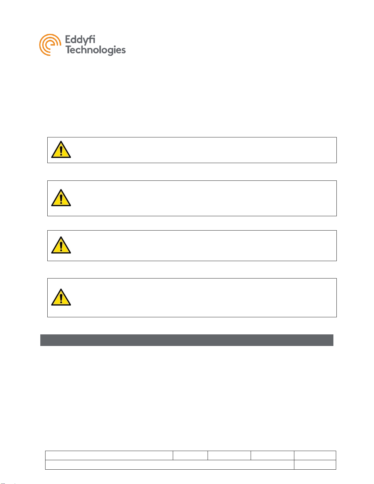
Interface Box Connection
Optionally, the TriTrax™ 200 may be operated through a PC or laptop computer running ICON software.
To connect to and power the vehicle, an interface box is required. To set up an PC based control system
with an Interface box, do the following;
Set-up:
1. Connect the interface box to AC power using an equipment power cord.
2. Connect the tether (or reel deck cable).
3. Connect the communication port to the control computer using a USB cable.
4. Connect video equipment as needed (monitors, recording devices, etc).
a. Front camera: Top row RCA jacks A, B, C.
b. Rear camera: Bottom row RCA jacks D, E, F.
The interface box may be ordered with optional features such as video capture to USB or video format
conversion. Additional connectors may be present on the rear center panel of the enclosure.
1. Connect SD Video A port to control computer using USB3 cable for front camera video capture.
2. Connect SD Video B port to control computer using USB3 cable for rear camera video capture.
IMPORTANT: USB3 cables are required for video capture (SD VIDEO A / B) to maintain video
quality.
TriTrax™ 200 Vertical Crawler
Document: UMDT017749.docm
Revision: A02
Created by: JS
Date: 13 Apr 2021
IPN: 3094329-A02
Source Location: C:\ePDM\ISLEng\Products\DT-VersaTrax100MkII\Manuals\UMDT017749.docm
Page 11 of 36
User Manual
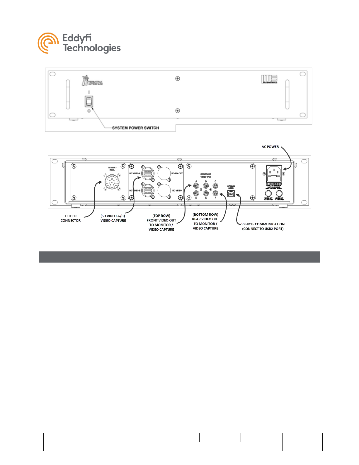
Vehicle and Tether Connection
It is important that the tether be properly connected to the vehicle –otherwise damage or loss of the system
may result.
1. Connect the vehicle end of tether to the back of the vertical crawler. Visually line up the key in the
connector before mating. Fully screw down and hand-tighten the locking collar. Do not use tools
because the connector can then be easily be overtightened.
2. Secure both lanyards to the Kellems grip using a quick link as illustrated below. Adjust the Kellems
grip position to maintain a small amount of slack tether regardless the direction the tether is pulled.
3. Verify all device whips from the harness block to their respective components are securely con-
nected, and the whips are free from damage.
4. Ensure all unused connectors are capped with dummy plugs to insulate and protect their electrical
contacts.
TriTrax™ 200 Vertical Crawler
Document: UMDT017749.docm
Revision: A02
Created by: JS
Date: 13 Apr 2021
IPN: 3094329-A02
Source Location: C:\ePDM\ISLEng\Products\DT-VersaTrax100MkII\Manuals\UMDT017749.docm
Page 12 of 36
User Manual
TriTrax™ 200 Vertical Crawler
Document: UMDT017749.docm
Revision: A02
Created by: JS
Date: 13 Apr 2021
IPN: 3094329-A02
Source Location: C:\ePDM\ISLEng\Products\DT-VersaTrax100MkII\Manuals\UMDT017749.docm
Page 13 of 36
User Manual
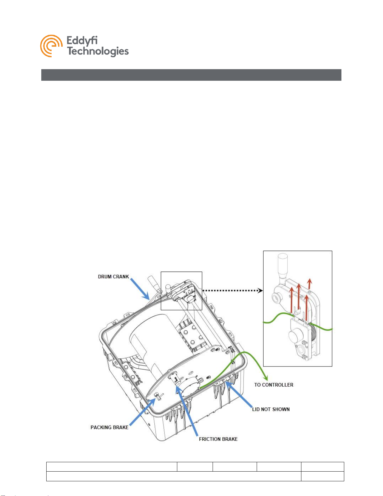
Portable Reel Setup
If your system includes a portable reel, follow these steps to operate:
1. Remove the shipping cap from the front of the case and insert the crank handle.
2. Connect the deck cable from the reel to the controller.
3. Disengage the packing brake (pull back and turn on the locking pin).
4. Make sure the friction brake is engaged - disengaging the friction brake can result in slack tether
resulting in potentially jamming the reel.
5. Unwind some tether and connect the tether to the vehicle.
6. Run the tether through the level wind as follows:
a. There is an access slot which must be opened by lifting up on the two exposed screw
heads to raise the tether support shafts.
b. Pull up on both sides of the axle on the top wheel and slide the tether beneath it - failing to
lift up on the wheel can scuff and damage the tether.
c. Make sure that the two wheels that sandwich the tether top and bottom in the level wind
are tracking properly as the tether is paid out - this tells the controller how much tether the
reel has unwound and how far your vehicle has travelled.

TriTrax™ 200 Vertical Crawler
Document: UMDT017749.docm
Revision: A02
Created by: JS
Date: 13 Apr 2021
IPN: 3094329-A02
Source Location: C:\ePDM\ISLEng\Products\DT-VersaTrax100MkII\Manuals\UMDT017749.docm
Page 14 of 36
User Manual
Mini-Reel Setup
If your system includes a Mini-Reel, follow these steps to operate:
1. Remove the Mini-Reel from the shipping case.
2. Connect the deck cable from the reel to the Video Interface and Power Supply.
3. Connect the encoder deck cable from the reel to the Video Interface and Power Supply (if provided
with Mini-Reel).
4. Disengage the shipping brake.
5. Make sure the friction brake is engaged –disengaging the friction brake can result in slack tether
resulting in potentially jamming the reel.
6. Unwind some tether and connect the tether to the vehicle.

TriTrax™ 200 Vertical Crawler
Document: UMDT017749.docm
Revision: A02
Created by: JS
Date: 13 Apr 2021
IPN: 3094329-A02
Source Location: C:\ePDM\ISLEng\Products\DT-VersaTrax100MkII\Manuals\UMDT017749.docm
Page 15 of 36
User Manual
Tether Handling
The tether is a very important part of the vehicle system. It feeds power and control signals to the
system and returns data to the controller. If the tether is damaged from improper use, poor handling or an
accident, the system may become inoperable. This could lead to significant downtime, loss of production,
and avoidable costly repairs. It is encouraged to stress the importance of the tether and its use to anyone
operating or maintaining the system. For maximum tether life and reliability, we recommend the following
tether handling tips.
•Do not step on the tether
•Do not drive over the tether
•Do not bend the tether beyond its minimum bend radius
•Do not kink the tether
•Do not snap load the tether
•Avoid loading the tether whenever possible
•Always use the cable grip strain relief if applicable to your system
•Regularly inspect the tether for damage
•Regularly clean the tether
Note:
Protecting the conductors inside the tether is critical to the life and operation of the tether. Proper
tether handling and care will result in extended tether life and system reliability.
Connector Handling
Connectors are an essential part of system reliability. They must be properly maintained and cared for to
ensure long life and reliability. It is recommended to follow these steps to help prevent damage and increase
the life of connectors.
•Always put the cap back on the tether bulkhead when the tether is disconnected
•Always inspect the end of the connector prior to engaging
•Never plug in a dirty or damaged connector
•Visually align keyways or locating pins prior to engaging the connector
•Always fully engage or tighten the connector
•Secure locking collars finger tight
•Install dummy plugs on unused connectors
•Disconnect by pulling straight, not on an angle
•Do not pull on the cable to disengage the connector
IMPORTANT: Never “Hot Plug” any connector, this will result in internal damage to the electron-
ics. Power down the system prior to connecting the tether or any of the modular components.

TriTrax™ 200 Vertical Crawler
Document: UMDT017749.docm
Revision: A02
Created by: JS
Date: 13 Apr 2021
IPN: 3094329-A02
Source Location: C:\ePDM\ISLEng\Products\DT-VersaTrax100MkII\Manuals\UMDT017749.docm
Page 16 of 36
User Manual
Note:
Never use WD-40 or similar solvent-based fluids on connectors or crawlers. These will cause the
rubber parts of the connector or crawler to soften and swell rendering them inoperable.
SubConn Connector: Lubrication and Cleaning
•Periodically apply Molykote 111 silicone grease or equivalent before mating connectors
•For dry mate connections, a layer of grease corresponding to 1/10 the socket depth should be
applied to the female connector
•After greasing, fully mate the male and female connector and remove excess grease from the
connector joint
•General cleaning and removal of sand or mud on a connector should be performed using a
spray-based contact cleaner like isopropyl alcohol
Impulse Connector: Lubrication and Cleaning
•Lubricate mating surfaces regularly with 3M Silicone spray or equivalent, DO NOT GREASE
•Lubricate O-rings with Molykote 111 or equivalent
•Use dust caps to protect connectors wherever possible
•Clean connectors with soap and fresh water, rinse out with alcohol and allow connector to air
dry before using.
TriTrax™ 200 Vertical Crawler
Document: UMDT017749.docm
Revision: A02
Created by: JS
Date: 13 Apr 2021
IPN: 3094329-A02
Source Location: C:\ePDM\ISLEng\Products\DT-VersaTrax100MkII\Manuals\UMDT017749.docm
Page 17 of 36
User Manual
Vehicle Configuration
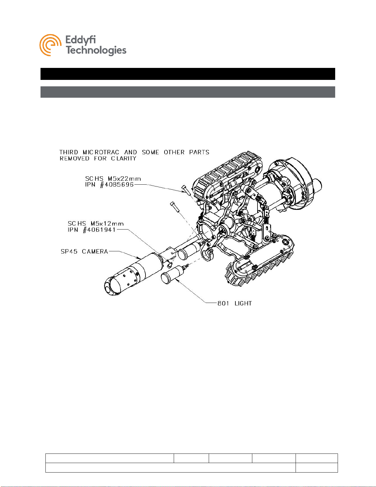
Front Camera Removal / Installation
The Spectrum™45 and lights are held onto the vehicle using a simple clamping fixture. To remove the
camera or a light, loosen the clamping M5 x 12 mm SHCS and slide the camera or light out of the fixture
as shown below. When reinstalling, ensure the connectors and locking collars are fully engaged –make
sure to properly align the pins on the mating connectors.

TriTrax™ 200 Vertical Crawler
Document: UMDT017749.docm
Revision: A02
Created by: JS
Date: 13 Apr 2021
IPN: 3094329-A02
Source Location: C:\ePDM\ISLEng\Products\DT-VersaTrax100MkII\Manuals\UMDT017749.docm
Page 18 of 36
User Manual
Size Configuration
Track Spacers:
Tracks on TriTrax™ 200 vehicle are remotely adjustable within a 100mm (4-inch) range. To engage the full
range of pipe diameters, two sizes of spacers are used as follows:
a. Base Configuration: No spacers: Ø203mm to Ø305mm (8” to 12”) pipe
b. Extension 50mm (2 inch) spacers: Ø305mm to Ø405mm (12” to 16”) pipe
c. Extension 75mm (3 inch) spacers: Ø355mm to Ø455mm (14” to 18”) pipe
Note that a 100mm (4 inch) spacer is optionally available but may compromise vehicle stability.
Microtrac Belt Extensions:
•Standard Length Microtrac - For the Base 12-inch configuration, the Microtracs are configured
with their standard-length belts.
•Extended Length Microtrac –Configurations using 2, 3, or 4-inch spacers require the Microtrac
belt extensions to ensure vehicle stability.
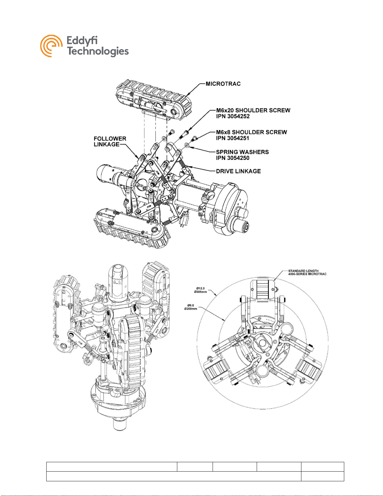
Base Configuration Ø203mm to Ø305mm (8” to 12”) pipe:In the base configuration, Microtracs are
connected directly to the expansion linkages as illustrated below using the side mounting holes. Note that
all tracks are connected to the linkages in the same way,whether configured for left or right-hand operation.
Also note that tracks are equipped with the standard length track belt for compact operation.
To assemble the base configuration, do the following as shown below:
1. Connect the front follower linkages using M6x8mm low profile shoulder screws (IPN 3054251) with
plastic spring washers beneath the heads.
2. Connect the rear follower linkages using M6x8mm shoulder screws with plastic spring washers
(IPN 3054250) beneath the heads.
3. Connect the drive linkages last using M6x20mm (IPN 3054252) shoulder screws.
4. Connect the track connector –make sure to align the mating pins correctly.
5. Repeat this procedure for each of the other two tracks.
Track removal is the opposite of installation
TriTrax™ 200 Vertical Crawler
Document: UMDT017749.docm
Revision: A02
Created by: JS
Date: 13 Apr 2021
IPN: 3094329-A02
Source Location: C:\ePDM\ISLEng\Products\DT-VersaTrax100MkII\Manuals\UMDT017749.docm
Page 19 of 36
User Manual
Figure 1: 203mm-305mm (8 to 12 Inch) Configuration.

TriTrax™ 200 Vertical Crawler
Document: UMDT017749.docm
Revision: A02
Created by: JS
Date: 13 Apr 2021
IPN: 3094329-A02
Source Location: C:\ePDM\ISLEng\Products\DT-VersaTrax100MkII\Manuals\UMDT017749.docm
Page 20 of 36
User Manual
Extended Configurations: To increase the operating size range, install the 50mm (2 inch) or 75mm (3
inch) extension brackets onto the linkages. Note that the extended length track belt is installed for increased
vehicle stability in large diameter pipes.
To install either size of extension brackets, do the following as shown below:
1. Fasten either the 50 (2 inch) or 75mm (3 inch) track spacer to the spacer base using 4x M5x16mm
Flat Head Machine Screws.
2. Attach the Microtrac to the extension bracket using 4x M5x10mm Socket Head Cap Screws.
3. Attach the spacer base to the expansion linkages as detailed in the previous section.
4. Ensure there is enough cable fed through the chassis to plug in the track. Wires can generally be
secured to the long bushing on the driver linkage using a zip-tie.
5. Connect the track connector –make sure to align the mating pins correctly, and fully engage the
locking collar.
6. Repeat this procedure for each of the other two tracks.
Bracket removal is the opposite of installation
Table of contents
Other eddyfi Analytical Instrument manuals

Popular Analytical Instrument manuals by other brands


SAEHANUL BIOTECH
SAEHANUL BIOTECH K-scope SO-05 manual

Ryobi
Ryobi RP4010 Operator's manual

VOLTCRAFT
VOLTCRAFT BS-17+ operating instructions

Extech Instruments
Extech Instruments CO210 user manual

Insight Vision
Insight Vision Xpress user manual

Keysight Technologies
Keysight Technologies B2900A Series Demo guide