eddyfi Sharck User manual

Sharck™Probe
for Reddy™Inspection
User’s Guide
Version 1.1
Date: 2015-07-28

2 | P a g e
Table of Contents
1. Probe Description ............................................................................ 3
2. TECA™ Technology ........................................................................... 4
3. Getting Started ............................................................................... 6
4. Setting Up Your Inspection................................................................ 11
4a. Opening an Existing Setup.......................................................................11
4b. Creating a New Setup with the Setup Wizard ...............................................13
5. Nulling the Sharck Probe .................................................................. 18
6. Calibrating the Sharck Probe ............................................................. 19
7. Collecting Data .............................................................................. 21
8. Saving Data................................................................................... 24
9. Analyzing Data............................................................................... 25
9a. Available C-Scans..................................................................................25
9b. Analysis Methodology.............................................................................25
9c. Analyzing Data with Reddy ......................................................................27
10. Saving and Reporting ..................................................................... 30

3 | P a g e
1. Probe Description
The medium Sharck™probe used in this guide contains two rows of 11 independent fingers. This
array probe (SHARCK-W053-R-N05S) offers a coverage or active area of 53 mm (2.1 in). Other
sizes of Sharck array probes are also available.
Figure 1 Medium Shark probe
Note
The small Sharck probe is compatible with the 32-channel and 64-channel Reddy™, while the
medium Sharck is best suited for the 64-channel Reddy. The large Sharck probe is not
compatible with Reddy, as it requires 128 channels (Ectane® 128 or 256).
All the fingers of Sharck probes (patent pending) contain a three-coil assembly operating in a
specific transmit/receive mode called tangential that enables measuring variations of the eddy
currents distribution. This is referred to as tangential eddy current array or TECA™. TECA was
developed to detect and size the length and depth of axial surface-breaking linear indications
in carbon steel. It is also capable of also detecting transverse cracks (perpendicular to the scan
axis). TECA’s coils use two fixed frequencies: 20 kHz and 80 kHz.

4 | P a g e
All Sharck probes are equipped with a high-resolution magnetic wheel encoder
(20.53 points/mm). SHARCK-W053-R-N05S comes with a 12-pin encoder connector for Reddy,
and a standard 5 m cable. The encoder (and guiding wheels) can easily be removed for cleaning
and maintenance.
Figure 2 Sharck encoder and guiding wheels are removable
For more information about the Sharck (description, specifications and typical performance),
refer to the Probe Information document provided with the probes and the 4-page brochure.
2. TECA™ Technology
TECA’s coil arrangement and tangential operation mode enable obtaining a very particular eddy
current signal for surface-breaking cracks in carbon steel. The TECA pancake coil’s axis is
parallel to the surface under test instead of being perpendicular, as is typical in eddy current
testing when using pancake coils. As illustrated below, this coil orientation helps eddy currents
to dive underneath cracks, offering valuable information about their depth.
Each finger of the Sharck probes contain three coils: two tangential operating in
transmit/receive mode and a third whose axis is perpendicular to the surface under test. The
tangential coils are used to measure the depth of cracks, while the third coil is used to position
cracks, measure their length, and to detect transverse cracks.
Figure 3 Simplified TECA working principle
Coils scanning the surface
Induced eddy currents
5 | P a g e
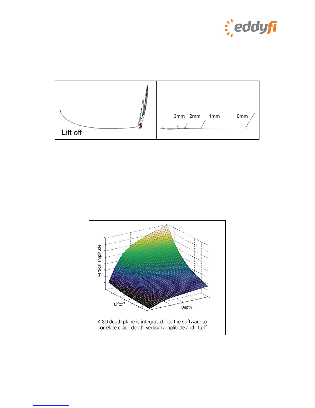
The main characteristics of TECA signals are:
•Almost flat liftoff signal
•Crack-like indications approximately 90° relative to the liftoff signal
•All crack-like indications feature the same phase shift
•Signal amplitude linked to the defect depth
Figure 4 Liftoff and phase shift
Obviously, the vertical amplitude of a given indication is impacted by lift off. As shown above,
the vertical component of the signal can be reduced by a factor 2 or 3 when there is significant
lift off. However, since the coil design allows for monitoring the lift off, it can be measured in
order to adjust depth sizing accordingly. Ultimately, the technique relies on multiple depth
curves that are calibrated with various lift off values. The result is equivalent to a 3D “depth
plane” allowing to correlate crack depth, vertical amplitude and lift off (horizontal component),
as illustrated in the next figure.
Figure 5 A 3D “depth plane”is integrated into the software to correlate
crack depth, vertical amplitude and liftoff

6 | P a g e
3. Getting Started
Figures below summarise the names given to the various part of the Reddy’s interface.
Figure 6 Backstage window
Figure 7 Front stage window
Ribbons
Status
icons
Display
area
File
navigator
Collapsable tables
Readings

7 | P a g e
1. Connect the Sharck probe to Reddy: both the 160-pin ECA connector and the 12-pin encoder
connector (I/O).
2. Turn on Reddy. (Refer to the Reddy user’s guide for details.)
Notes
•You can connect and disconnect the Sharck probe while the instrument is running.
•Reddy performs a compatibility check on the probe to verify that the current setup is valid.
3. In the backstage view, tap Project.
4. Create a new inspection folder or open an existing one by tapping Create Inspection or
Open Inspection, respectively.
Figure 8 Backstage view: Create/Open inspection

8 | P a g e
Figure 9 Creating an inspection project
5. If you are creating a new inspection folder, type its name in the Inspection text box.
6. Tap OK.
Note
When you open a new inspection folder for the first time and press on Start Working, the
Acquisition Summary dialog box appears. The information you specify here is associated to this
inspection folder. You can tap Acquisition Summary in the backstage view to open it again at
a later time. When you are done, tap OK.
Figure 10 Acquisition Summary dialog box
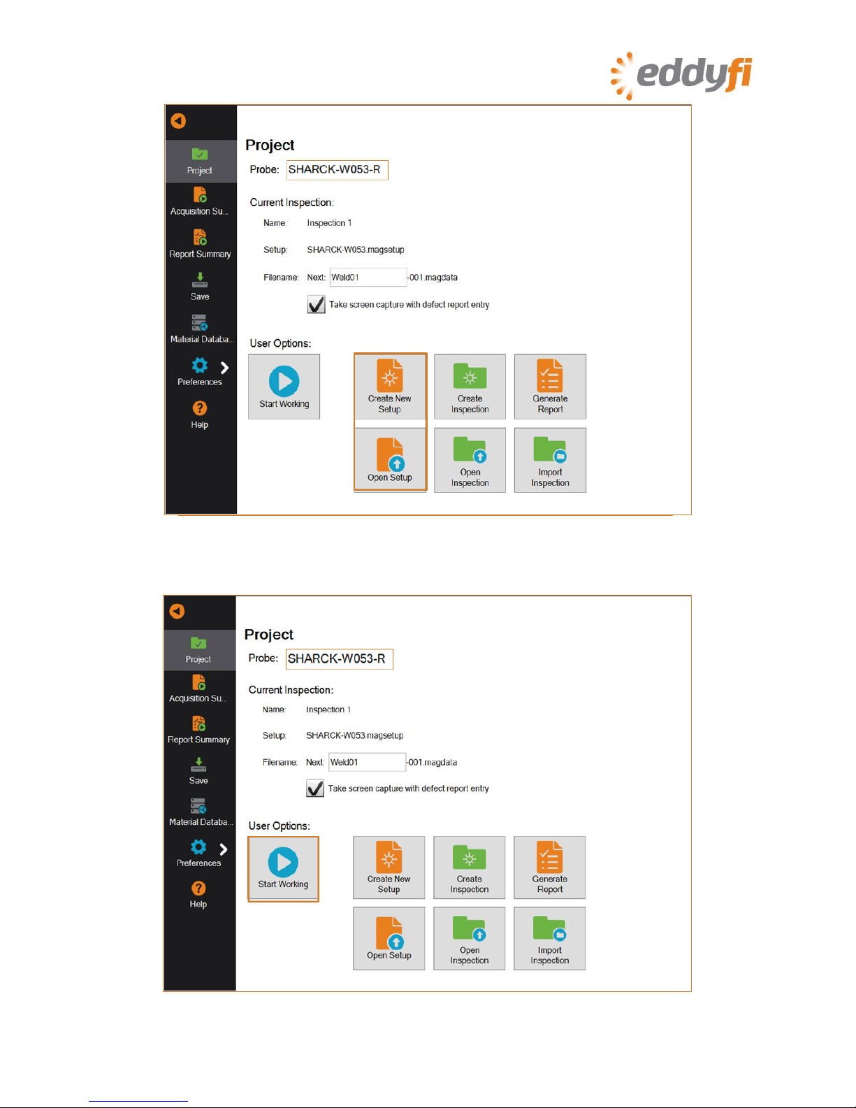
7. Create a new setup or open an existing setup by tapping Create New Setup or Open Setup,
respectively.
9 | P a g e
Figure 11 Backstage view: Create/Open setup
8. Once you are done, tap Start Working.
Figure 12 Backstage view: Start Working

10 | P a g e
Figure 13 Front stage view

11 | P a g e
4. Setting Up Your Inspection
4a. Opening an Existing Setup
1. In the backstage view, tap Open Setup.
Figure 14 Backstage view: Open Setup
2. In the Open Setup dialog box, on the Master list, select the appropriate setup file (in this
case, SHARCK-W053).
All standard probe setups are available in Reddy and are available on this list.
Figure 15 Open Setup dialog box

12 | P a g e
3. Tap OK.
4. Verify that the setup file is correctly applied.
Figure 16 Verifying the applied setup
13 | P a g e
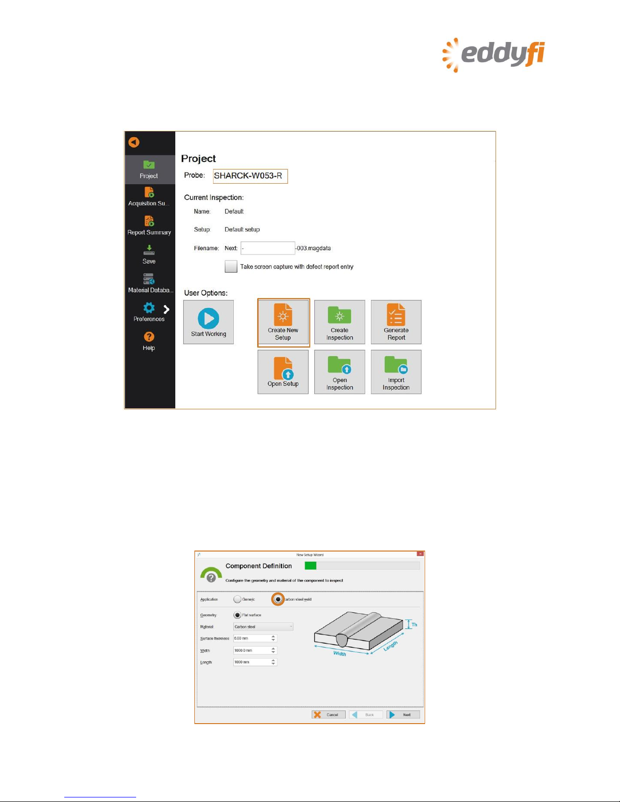
4b. Creating a New Setup with the Setup Wizard
1. In the backstage view, tap Create New Setup.
The new setup wizard starts.
Figure 17 Backstage view: Create New Setup
Note
Every step of the setup wizard has default values. You can modify them to suit your needs and
applications.
2. In the Component Definition dialog box, select Carbon steel weld, and then adjust the
parameters for the part(s) to be inspected, if desired. Note that from here on, for the
Sharck probe, all default values of the Wizard are designed to be adequate.
Figure 18 Component definition
14 | P a g e
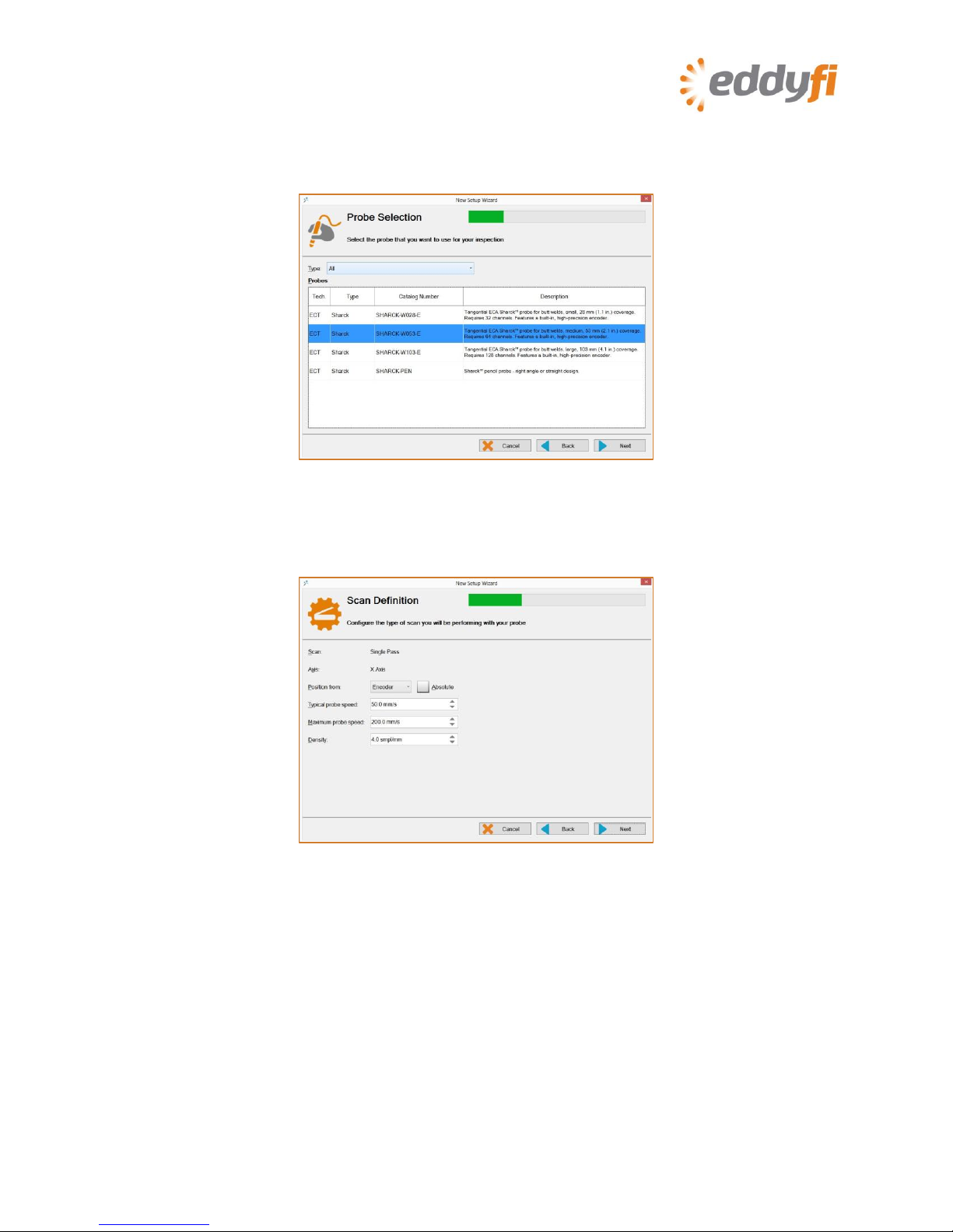
3. Tap Next.
4. In Probe Selection, select the setup corresponding to the Sharck probe connected to
Reddy.
Figure 19 Probe selection
5. Tap Next.
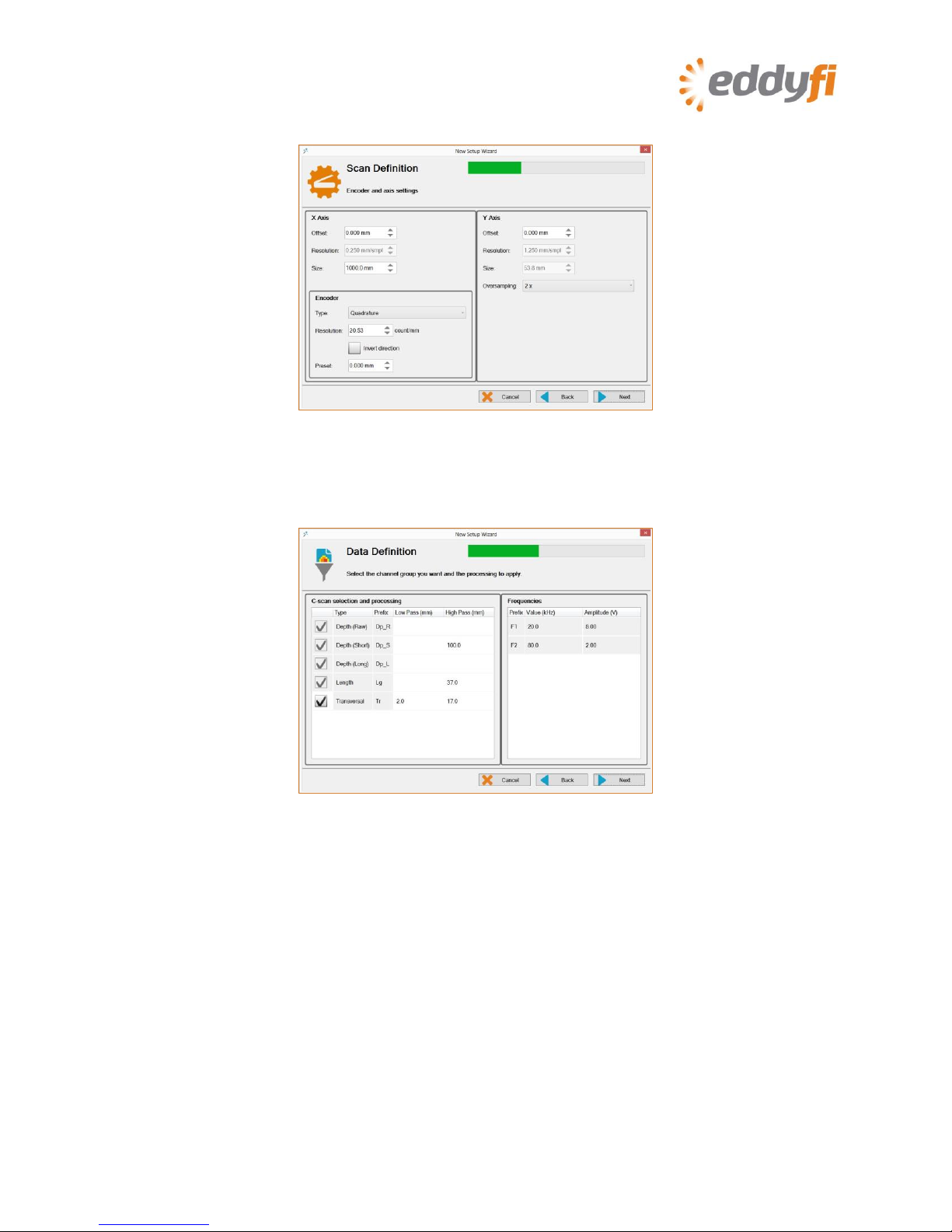
6. In Scan Definition, select the encoder and specify the type of scan.
Figure 20 Scan definition: configure scan
7. Tap Next.
15 | P a g e
8. Configure the encoder and the starting position.
Figure 21 Scan definition: configure encoder and start position
9. Tap Next.
10. In Data Definition, adjust the properties of your filters.
Figure 22 Data definition: configuring filters
Note
Sharck probe setups are tailored for carbon steel. That is why you cannot change the
frequencies and injection voltages of these setups. Moreover, as most channel groups are
necessary for analysis, you can only disable the transverse group.
11. Tap Next.

16 | P a g e
12. In Indication Codes, create the indication code list you wish to use during your analysis.
Figure 23 Indication codes
13. Tap Next.
14. In Display, configure your display properties.
Figure 24 Display properties
15. Tap Next.

17 | P a g e
16. In Display, configure the layout of your display.
Figure 25 Display layout
Note
The layout highlighted in blue is the layout displayed when you start working. To select any of
the other layouts selected in the wizard, press the Change layout button ( ) on Reddy’s
keypad or, in the front stage view, tap Layout, and then Selecting Layout.
18 | P a g e
5. Nulling the Sharck Probe
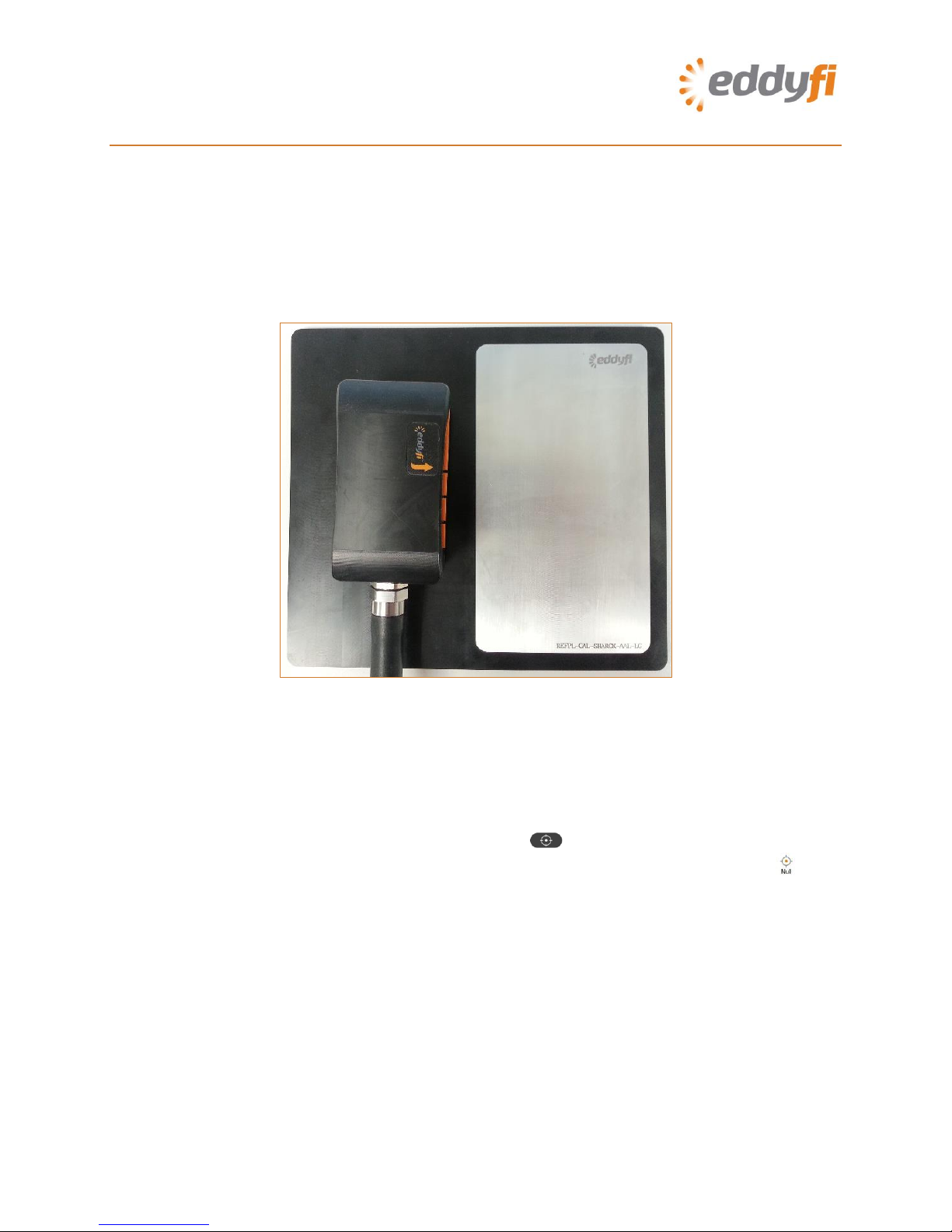
1. Position the Sharck probe on the plastic portion of Eddyfi’s normalization plate (REFPL-CAL-
SHARCK-AAL-LG).
Note
The normalization plate should be on a steady, flat surface and shall be at least 10 cm (4 in)
from any ferritic surface.
2. Apply even pressure on the probe.
Figure 26 Nulling the Sharck probe
Note
To balance the probe, we strongly recommend that you press the probe onto a non-metallic
surface, instead of keeping it in the air. This avoids having one or only a few fingers compressed
at a lower position than neighboring fingers, which can affect the probe’s balance.
3. On Reddy’s keypad, press the Probe nulling button ).
Alternately, in the front stage view, on the Home or Calibration ribbon, tap Null ( ).
19 | P a g e
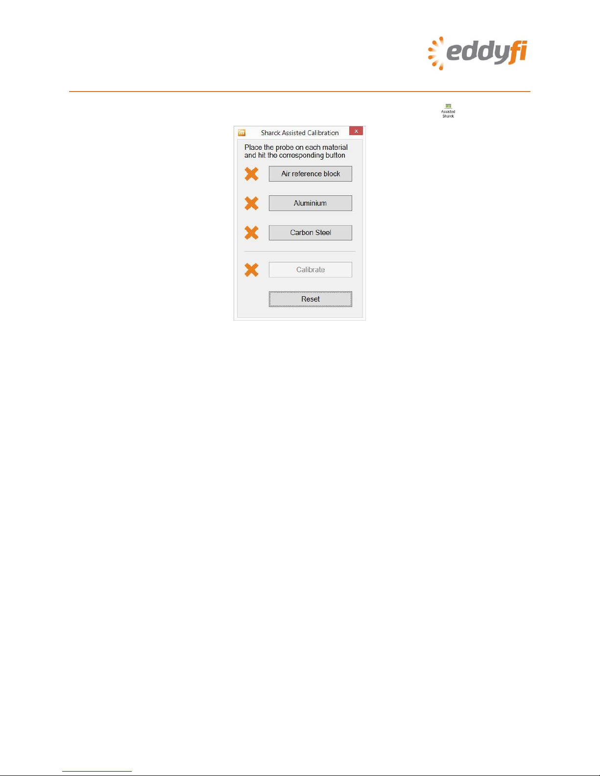
6. Calibrating the Sharck Probe
1. In the front stage view, on the Calibration ribbon, tap Assisted Sharck ( ).
Figure 27 Sharck Assisted Calibration
2. Position the Sharck probe on the plastic portion of Eddyfi’s normalization plate (REFPL-CAL-
SHARCK-AAL-LG).
Note
The normalization plate should be on a steady, flat surface and shall be at least 10 cm (4 in)
from any ferritic surface.
3. Apply even pressure on the probe.
4. In the Sharck Assisted Calibration dialog box, tap Air reference block.
When the necessary data is acquired, a green check mark appears next to Air reference
block.
5. Position the Sharck probe on the aluminum portion of Eddyfi’s normalization plate.
6. Apply even pressure on the probe.
7. In the Sharck Assisted Calibration dialog box, tap Aluminum.
When the necessary data is acquired, a green check mark appears next to Aluminum.
8. Position the Sharck probe on the carbon steel component to be tested, near the weld (but
not over the weld)
9. Apply even pressure on the probe.
10. In the Sharck Assisted Calibration dialog box, tap Carbon steel and move the probe, if
there is sufficient space allowing for it. Otherwise keep it still during the few seconds
required to acquire the steel calibration data.
When the necessary data is acquired, a green check mark appears next to Carbon steel.

20 | P a g e
Note
If non-magnetic paint or coating is present, there is no need to remove it (unless it is thicker
than 3 mm (0.118 in). The Sharck calibration process takes that lift-off into account and
manages accordingly.
11. In the Sharck Assisted Calibration dialog box, tap Calibrate ( )..
When the necessary data is acquired, a green check mark appears next to Calibrate.
Figure 28 Sharck Assisted Calibration: Calibration complete
Note
If, for any reason, you must normalize the probe again, tap Reset before you perform the above
procedure.
12. Tap the red “x” on the top right corner of the dialog box to close it.
Table of contents
Other eddyfi Measuring Instrument manuals

Popular Measuring Instrument manuals by other brands

Endress+Hauser
Endress+Hauser Proline Promag P 100 operating instructions

Agilent Technologies
Agilent Technologies N9010A Configuration guide

CET
CET PMC-53 Series user manual

PRUFTECHNIK
PRUFTECHNIK VIBTOOL operating instructions

Onicon
Onicon F-5100 Inline Installation and operation guide

Emerson
Emerson AMS 2140 Pocket guide

Baumer
Baumer FKDM 22P1901/S14F user manual

Onset
Onset HOBO MicroRX RX210 Series quick start

Comet System
Comet System COMMETER C3121P instruction manual

Keysight
Keysight P937 A Series Service guide

Proceq
Proceq Zehntner ZRM 6013+ instruction manual

Inovonics
Inovonics FM SiteStreamer+ SOFIA 565 Installation & user guide


