PRUFTECHNIK VIBTOOL User manual

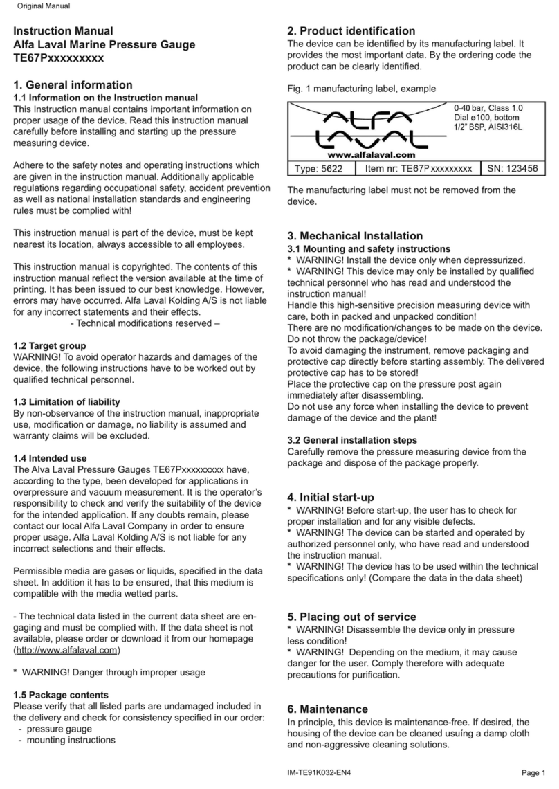
Edition February 2009
Version 1.02
Order number VIB 9.497 G
Dear Customer,
If you have any suggestions for improving
this instruction manual or the instrument
itself or any of its accessories, please let us
know.
PRÜFTECHNIK AG
Fax: +49 (0)89 99616-300
eMail: [email protected]
VIBTOOL®
Machine condition
via Bluetooth
Operating instructions
Advanced Test Equipment Rentals
www.atecorp.com 800-404-ATEC (2832)
®
E
s
t
a
b
l
i
s
h
e
d
1
9
8
1

VIBTOOL 02.2009
2
Contents
Introduction .......................................................... 4
Program overview ................................................ 8
Operating modes .......................................................... 8
Measurement modes .................................................... 9
VIBTOOL operation ............................................. 11
Operating keys ........................................................... 11
Display ........................................................................ 12
VIBTOOL sensors and connections .............................. 12
Rechargeable battery .................................................. 13
Battery charge state ............................................................ 13
How to connect the VIBTOOL charger ................................. 13
VIBTOOL behavior during charging...................................... 14
Typical measurement procedure .................................. 15
Bluetooth operating mode .................................................. 15
‘Preset measurements’ operating mode .............................. 17
Measurement selection ....................................................... 17
Unit settings (Device setup) ......................................... 20
Turn off time (Device setup) ........................................ 22
Display battery status (Device setup) ........................... 24
Vibration measurements .................................... 25
ISO vibration monitoring standard ....................................... 26
Ideal measurement position ................................................ 27
Where to measure .............................................................. 27
Vibration measurements with VIBTOOL ....................... 28
Vibration display ................................................................. 28
Bearing diagnosis ............................................... 29
What are shock pulses? ....................................................... 30
Where do shock pulses occur? ............................................ 30
How are shock pulses actually measured? ........................... 31
How are shock pulses evaluated? ........................................ 31
The carpet value .................................................................. 32
Maximum value .................................................................. 33
The measurement location .......................................... 34
1. One mechanical interface ................................................ 34
2. Short signal path ............................................................. 35
3. Loaded region ................................................................. 35
4. Directly at the bearing ..................................................... 36
5. Metallic, flat, clean (preferably machine-faced) ............... 36
Bearing diagnosis with VIBTOOL ................................. 37
Bearing diagnosis display ..................................................... 37

VIBTOOL 02.2009
3
© 2005 PRÜFTECHNIK AG; all rights reserved
Both this manual and the product it describes are copyrighted. All rights
belong to the publisher. The manual may not be copied, reproduced,
translated or made accessible to a third party in any form, neither in its
entirety nor as an excerpt.
No liability may be claimed against the publisher regarding the product
described in this manual. The publisher assumes no liability for accuracy of
the manual contents. Furthermore, under no circumstances may the
publisher be held liable for direct or indirect damage of any kind resulting
from use of the product or the manual, even if the publisher has expressly
indicated the potential for occurrence of such damage.
The publisher assumes no liability for any product defects. This warranty and
liability limitation applies to all distributors and sales partners as well.
The trademarks mentioned in this manual are generally noted as such and
are the property of their owners. Lack of such designation does not imply,
however, that names are not protected by trademark laws.
Cavitation measurement .................................... 39
What is cavitation? .............................................................. 39
Cavitation evaluation .......................................................... 40
Ideal measurement position ................................................ 40
Cavitation measurements with VIBTOOL ..................... 41
Cavitation measurement display .......................................... 41
RPM measurement .............................................. 43
Interference from external light sources ............................... 44
RPM measurement display .................................................. 45
Temperature measurement ................................ 47
Temperature measurement display ...................................... 48
Appendix ............................................................. 49
Warranty, service and care .......................................... 49
Update via serial cable ........................................................ 51
Firmware version ................................................................. 52
VIBTOOL accessories ................................................... 53
Spare temperature probe - VIB 8.605 .................................. 53
External or permanently installed sensors ............................ 54
Countersink bit - VIB 8.610 ................................................. 56
VIBTOOL delivery package .......................................... 57
Technical data ............................................................. 59

VIBTOOL 02.2009
4
Introduction
Introduction
VIBTOOL is a robust hand-held measurement instrument
with built-in sensors for vibration, RPM and temperature.
These sensors can be used to measure the following 5
parameters:
Vibration acceleration
Vibration velocity
Bearing condition (Shock Pulse Method)
Cavitation
Temperature
RPM
Two operating modes are available:
1. ‘Bluetooth’:
VIBTOOL obtains the measurement parameters from an
associated PDA computer via a wireless Bluetooth con-
nection. The measurement results are transferred to the
PDA computer and, from there, evaluated and saved
using special software.
2. ‘Preset measurements’
VIBTOOL contains measurement tasks with preset pa-
rameters. The measurement results can only be dis-
played. It is not possible to store the data on or to
transfer them to a PDA.
External vibration or temperature probes can be plugged in
to measure at locations that are difficult to reach.
VIBTOOL's primary function is as a 'multimeter' for general
on-the-spot measurements. Engineers can walk around the
machine hall with VIBTOOL and take immediate measure-
ments of machine conditions. Try it out...
Bluetooth
PDA

VIBTOOL 02.2009
5
Safety notes
The VIBTOOL housing may only be opened by authorized
technical personnel.
Operation and maintenance are to be performed only by
properly trained personnel.
Repairs to the VIBTOOL instrument may be carried out
only by a PRÜFTECHNIK-authorized service technician.
Only original spare parts and accessories may be used.
Only properly functioning, regularly-maintained electrical
equipment may be used. Any defects such as broken plugs
or loose sockets must be corrected immediately. Damaged
cables must be replaced by an authorized service techni-
cian.
Any alterations that affect instrument design or operating
safety require explicit prior approval of PRÜFTECHNIK AG.
The relevant safety regulations must be observed during
measurements on machines.
Authorized use
- VIBTOOL may only be used to record machine vibration
signals, rotational speed and temperature values as well
as condition parameters of roller bearings in industrial
environments.
- For measurements with external transducers and for
data transmission via serial interface, only use the
connecting cable provided for this. Transducers and
cables may only be used for their respective intended
tasks as described in the corresponding product summa-
ries.
Any other use constitutes improper use and is prohibited.
PRÜFTECHNIK AG assumes no liability for damage result-
ing from improper use.
Moreover, the European installation instructions EN
60079-10:2003ff must be followed.
Attention!
Introduction

VIBTOOL 02.2009
6
Explosion hazardous areas
• VIBTOOL with intrinsic safety (VIB 2.700 EX) may only
be used with rechargeable batteries with the following
approval:
ZELM 05 ATEX 0243 U
• Rechargeable batteries must not be charged in explosive
environments! Only VIB 2.720 (EU), VIB 2.721 (USA) or
VIB 2.722 (UK) charging units may be used.
• The battery should not be removed under any circum-
stances! To replace a defective battery, VIBTOOL must
be sent back to the manufacturer.
• The accessories listed in the ‘Sensors & Accessories’
product catalog (VIB 9.663-1DG) are not allowed in
areas that contain inflammable dust!
• The VIBTOOL case (VIB 2.729) is not allowed in
explosion hazardous areas.
• Interface specification:
Analog output circuit: if the intrinsic safety protection is
type EEx ib IIC, it is only suitable for connection to
devices intended for this
UO= 11.6V
IO= 15mA
PO= 180mW
Ci= 70nF
CO= 1.5µF
Li= 300µH
LO= 60mH
Temperature sensor circuit: if the intrinsic safety protec-
tion is type EEx ib IIC, it is only suitable for connection
to devices intended for this
UO= 11.6V
IO= 15mA
PO= 180mW
CO= 1.5µF
LO= 60mH
Digital output circuit / charging socket: if the intrinsic
safety protection is type EEx ib IIC, it is only suitable for
connection to devices intended for this
UO= 8.4V / IO= 84mA
PO= 180mW / CO= 6.8µF
LO= 3mH
Introduction

VIBTOOL 02.2009
7
Introduction
About this manual
This manual describes the main functions of the VIBTOOL
instrument (type: VIB 2.700 EX / firmware version: 1.0x)
as well as the most important steps of its operation.
Symbols used in this manual
This symbol denotes information which must be fol-
lowed in order to avoid damage to the system or other
equipment.
This symbol denotes general information and tips
regarding VIBTOOL operation.
))
))
)
Note
Attention!

VIBTOOL 02.2009
8
Program overview
Device setup
Setting up the units and the turn off time.
Displaying battery status. See page 20 for
details.
Preset measurement
VIBTOOL works autonomously. Only the
preset measurements can be carried out
and the results can only be displayed.
See page 17 for details.
Bluetooth mode
VIBTOOL works in conjunction with a
PDA computer. Measurement parameters
and results are exchanged via Bluetooth
connection.
See page 15 for details.
Overview
Operating modes
Press M to switch on VIBTOOL
Press NEXT
Press NEXT

VIBTOOL 02.2009
9
Measurement modes
Temperature measurement
Extremely quick, easy, and accurate
See page 47 for details.
RPM measurement
Accurate non-contact RPM mea-
surement. See page 43 for details.
Bearing diagnosis
Monitors bearing condition
See page 29 for details.
Vibration measurement
Machine vibration at a glance
See page 25 for details.
Cavitation measurement
For avoiding damage to pumps
See page 39 for details.
Overview

VIBTOOL 02.2009
10
empty page

VIBTOOL 02.2009
11
VIBTOOL operation
Operating keys
DOWN & UP:
Navigate /
Turn off device
NEXT: Navigate / Change
operating mode
ENTER: Confirm / Scroll
NEXT & ENTER : Start
update via bluetooth
MEASURE:
- Turn on device
- Start measurement
- Measures continuously
while pressed
Turn on VIBTOOL by pressing the ‘M’ key until the LCD
lights up. After about one second, the device enters
Bluetooth mode, signified by the text ‘bt’ at the bottom of
the screen (see page 15 for details).
To display the type of Bluetooth module installed,
press and hold the ENTER key before switching on the
device with the M key. The following text appears for
approx. 2 seconds: “bt|19” or “bt|46”.
bt|19 = WML-C19 module is installed. VIBTOOL
instrumens with serial number < 999.
bt|46 = WML-C46 module is installed. VIBTOOL
instrumens with serial number > 1000.
Turn off VIBTOOL by pressing the DOWN and UP keys
simultaneously. The firmware revision and build number
will be briefly displayed before the device turns off (p. 52).
VIBTOOL turns off if no key is pressed for more than 10
minutes. VIBTOOL also turns off if any key is continuously
pressed for more than 3 minutes.
ENT
Operation
Turn on VIBTOOL
Turn off VIBTOOL
))
))
)
Note
ENT

VIBTOOL 02.2009
12
Operation
Display
VIBTOOL displays measurement results and status infor-
mation on the LCD display. Typical measurement screens
and the explanation of the individual screen symbols are
given in the respective measurement section.
Temperature probe
VIBTOOL sensors and connections
Rear view
A rear view of VIBTOOL is shown below. Here, it is possible
to extend and retract the temperature probe as indicated by
the arrows.
Top view
Temperature probe
Input for:
external hand probe or
permanently installed transducers
Optical RPM sensor
Vibration and
bearing sensor
Charging socket /
Serial port
Input for external
temperature probe
(remove built in
temperature probe)

VIBTOOL 02.2009
13
Rechargeable battery
VIBTOOL is supplied with power by a Lithium-Ion re-
chargeable battery. The battery is charged in the instru-
ment using the VIBTOOL charger.
The battery should not be removed under any circum-
stances! To replace a defective battery, VIBTOOL must
be sent back to the manufacturer.
Battery charge state
The charge status is indicated by the battery (‘Batt’) icon on
the display:
- ‘Batt’ flashes: battery is almost empty
This continues for a few minutes to enable any measure-
ments that are running to be completed and the battery
to be recharged.
- ‘Batt’ lights up: battery is being charged.
- ‘Batt’ is not displayed: battery is sufficiently charged.
The charge condition of the battery can also be viewed
in the Device Setup (see page 24)
How to connect the VIBTOOL charger
Connect the VIBTOOL charger to the charging socket on
the top of the instrument.
Procedure:
1. Flip the VIBTOOL temperature probe out to expose the
5-pin socket.
2. Connect the charger to the 5-pin socket as shown in the
diagram below. Check the notch for correct alignment.
This is a push fit, do not turn!
Operation
Attention!
))
))
)
Note
ENT
VIBTOOL charger
VIB 2.721

VIBTOOL 02.2009
14
Operation
While charging VIBTOOL, switch it off to keep the charging
time as short as possible.
VIBTOOL behavior during charging
1. VIBTOOL power is off – Power supply unit is plugged in:
If VIBTOOL is not fully discharged, the device switches
on and the messages ‘Char’ (= Charge) + ‘Strt’ (=Start)
appear consecutively on the display.
VIBTOOL then switches off while battery charging con-
tinues.
If the battery is fully discharged, the device switches on
and off repeatedly until it continues charging while it is
switched on (see also Point 2).
If VIBTOOL is left inactive, it switches off automatically
after 10 minutes.
2. VIBTOOL power is off – Power supply unit is removed:
VIBTOOL switches on. The message ‘Char’ - ‘Stop’
appears on the display for 7 seconds. Also, ‘Lo’ or the
battery charging level in percent appears before VIB-
TOOL switches back off.
3. If VIBTOOL is switched on while it is being charged:
VIBTOOL is ready for operation and the ‘Batt.’ symbol
lights up steadily to indicate charging.
4. If VIBTOOL is switched off while it is being charged:
The display switches off and charging continues.
5. VIBTOOL power is on – Charging stops (power supply
unit is removed or battery is full):
VIBTOOL remains ready for operation and the ‘Batt.’
symbol goes out.
6. VIBTOOL power is off – Charging is completed:
VIBTOOL switches back on and the messages ‘full’ +
‘charge’ appear consecutively on the display.
Press the M key to switch to operating mode, or switch
VIBTOOL back off: Unplug the charger from the mains
or press the UP/DOWN keys simultaneously.
If VIBTOOL is left inactive, it switches off automatically
after 10 minutes.

VIBTOOL 02.2009
15
Typical measurement procedure
Bluetooth operating mode
VIBTOOL receives all information for measurement via
Bluetooth from a PDA computer. This computer is used to
create measurement tasks with the corresponding soft-
ware.
Bluetooth mode is signified by ‘bt’ at the bottom of the
screen. In this mode the tool is ready to pair* with a host
device, or if it is already paired, to begin taking readings. A
Bluetooth pairing is not lost when the VIBTOOL is turned
off. A VIBTOOL can only be connected with one host device
at a time. When the VIBTOOL is communicating with a host
device vie Bluetooth, the ∆icon appears in the lower left
corner of its display.
Once VIBTOOL has been switched on, the ‘No data’ mes-
sage appears on the display. VIBTOOL is now ready to
receive the first measurement task:
After the measurement task has been received, the ‘rdy’
(ready) message appears. At the same time, the corre-
sponding measurement symbol flashes – e.g. for a vibration
measurement:
‘no data’ appears when
the device is switched on
Measurement task received
- ready to measure
Operation
* The host device must pair
with a Bluetooth peripheral
device before they can
communicate. Pairing consists
of exchanging information that
allows the two devices to
uniquely identify each other.

VIBTOOL 02.2009
16
))
))
)
Note
))
))
)
Note
VIBTOOL carries out several individual measurements
which are then averaged to produce a final result. VIB-
TOOL automatically sends the final result to the PDA.
To extend the measurement recording period, keep the
M key pressed. VIBTOOL starts the individual measure-
ment when the M key is released.
The measurement result is shown on the display until the
next measurement task is received.
If an external sensor is connected to VIBTOOL, this
sensor must also be used to carry out the measure-
ment! In this case, the integrated sensors are not used
for measurement.
Measurement result
Operation
Int and Et indicate whether an
internal or external sensor is
being used. If they disappear
then reappear, this indicates
that the measurement is
unstable - remeasure!
• Hold the sensor against the measurement location.
Make sure that the direction of measurement and the
contact pressure are correct.
• Press the M (Measure) key to start the measurement:

VIBTOOL 02.2009
17
‘Preset measurements’ operating mode
VIBTOOL contains the following preset measurement tasks
that can be carried out at any time:
• Vibration velocity - 10Hz to 1kHz
• Vibration velocity - 2Hz to 1kHz
• Shock pulse measurement - 36kHz bandpass
(bearing condition evaluation)
• Vibration acceleration - 0.5kHz to 10kHz
• Vibration acceleration - 1kHz to 10kHz
• Cavitation measurement - 36kHz bandpass
• RPM
• Temperature
The measurement results are displayed until the next
measurement is started. It is not possible to store the
results on or to transfer them to a PC.
Measurement selection
1. Vibration velocity
Switch on VIBTOOL and press NEXT until
‘Pr’ appears in the lower display field.
Vibration velocity 10Hz to 1kHz is select-
ed:
The corresponding symbol flashes and
the lower frequency (10-) appears on the
display.
To change the lower frequency, press
ENTER:
Vibration velocity 2Hz to 1kHz is now
selected: 2- (Hz).
ENT
Operation

VIBTOOL 02.2009
18
2. Shock pulse & Vibration acceleration:
Switch on VIBTOOL and press NEXT until
‘Pr’ appears in the lower display field.
Keep the DOWN key pressed until the
following display appears:
Shock pulse is selected when the ‘Bear-
ing’ symbol flashes and ‘SP’ (= ’Shock
Pulse’) appears on the display.
To select the vibration acceleration mea-
surement, press ENTER:
Vibration acceleration 0.5kHz to 10kHz
is selected: the ‘Bearing’ symbol flashes
and the lower frequency (0.5) appears on
the display.
To change the lower frequency to 1kHz,
press ENTER:
Vibration acceleration 1kHz to 10kHz is
now selected: 1.0 - (kHz).
To return to the shock pulse measure-
ment again, press ENTER.
ENT
ENT
ENT
Operation

VIBTOOL 02.2009
19
3. Temperature / RPM / Cavitation:
Switch on VIBTOOL and press NEXT until
‘Pr’ appears in the lower display field.
Keep the DOWN key pressed until the
following display appears and the respec-
tive symbol flashes:
- Temperature
- RPM
- Cavitation
Starting measurement
Hold the sensor against the measurement location. Make
sure that the direction of measurement and the contact
pressure are correct.
Press the M (Measure) key to start the
measurement:
The display that appears on the measure-
ment screen depends on which measure-
ment is selected. More details are given
at the end of the relevant chapter on
measurement.
Example:
‘Int’ and ‘Et’ indicate whether an internal
or external vibration sensor is being
used. If they disappear then reappear,
this indicates that the measurement is
unstable - remeasure!
After the measurement, click on the
NEXT key to return to the selection
screen.
Operation

VIBTOOL 02.2009
20
Unit settings (Device setup)
To change the units, proceed as follows:
Switch on VIBTOOL and press NEXT until
‘dE’ appears in the lower display field:
The VIBTOOL device setup is active when
‘unit’ and ‘dE’ appear on the display and
the ‘dim’ symbol flashes.
Press the ENTER key to enter the edit
mode.
Press the DOWN key repeatedly to select
the units one after the other:
1. Vibration velocity
2. Vibration acceleration
3. Temperature
4. Rotational speed
Press ENTER to change the settings:
1. mm/s <> inch/s
2. - - (=m/s²) <> g
3. °C <> °F
4. RPMx100 <> 1/s
Navigate back with the UP key and leave
the edit mode.
To leave the Device Setup again, press
the NEXT key. The ‘Bluetooth’ operating
mode is activated.
ENT
..
..
.
..
..
.
Operation
Note:
m/s² cannot be displayed:
‘ - - ’is shown instead!
ENT
Table of contents
Other PRUFTECHNIK Measuring Instrument manuals
