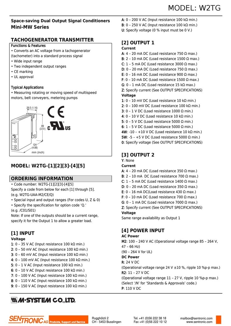
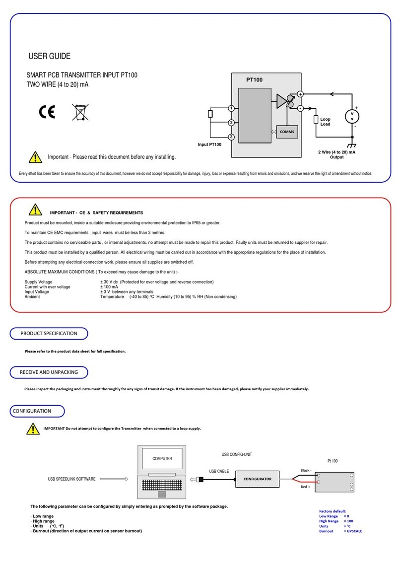
Eddystone Broadcast XE150 Series Owner's manual

Print Date 04/01/11 Page 1 of 42 E2165-00MA-04
Eddystone Broadcast
----
XE150/300 Series
FM Exciters
(2
nd
Series)
----
Installation
and
Operation
----
Issue 4
E2165-00MA-04
January 2011
----
Eddystone Broadcast Ltd.
26, Arden Rd.
Arden Forest Industrial Estate
Alcester, Warwickshire
B49 6EP, England
Tel. 44 (0)1789 762278
Fax. 44 (0)1789 766033
www.eddystone-broadcast.com

Print Date 04/01/11 Page 2 of 42 E2165-00MA-04
Intentional blank page

Print Date 04/01/11 Page 3 of 42 E2165-00MA-04
Index
SECTION ONE : INTRODUCTION
1.1 : GENERAL DESCRIPTION………………………………………………………………… Page 5
1.1.1 : Front Panel Module………………………….…………………………..……………...… Page 5
1.1.2 : Main and Input/Output Boards……….………………….………..………………..……. Page 6
1.1.3 : 150/300W Amplifier Module, Control and Power Supply………………………….….. Page 7
1.1.4 : 12V Supply and Fan Control Board……………………….……………….….……..…. Page 8
1.1.5 : Stereo Encoder Module (/S option only)…………….…………………..……………… Page 8
1.1.6 : Composite Input Module (/M Module only)………………………….………………….. Page 9
1.1.7 : Re-Broadcast Receiver Module (/R option only)….………….……..…………………. Page 9
1.2 : VARIANTS AND OPTIONS…………………………………………………………………Page 9
1.3 : TECHNICAL SPECIFICATIONS…………………………………………………………… Page 10
1.3.1: Common Specifications…………………………………………………………………… Page 10
1.3.2: Stereo Encoder Module Specifications (/S option only).……………………………..... Page 14
1.3.3: Composite Input Module Specifications (/M option only)..…………………………….. Page 15
1.3.4: Re-Broadcast Receiver Module Specifications (/R option only)………………………. Page 16
SECTION TWO : INSTALLATION
2.1 : PHYSICAL DIMENSIONS AND FITTING………………………………………………… Page 17
2.1.1 Installation Accessories……………………………………………………………………. Page 17
2.1.2 Rack Mounting………………………………………………………………………………. Page 18
2.2 EXTERNAL CONECTIONS………………………………………………………………….. Page 19
2.2.1 Mains Supply Connector.………………………………………………………………….. Page 19
2.2.2 RF Output Connector……………………………...……………………………………….. Page 19
2.2.3 SCA1/RDS, SCA2 and SCA3 Input Connectors………………………………………… Page 20
2.2.4 Mono/AES Input Connector……………………………..………………………….……… Page 20
2.2.5 Composite Input Connector…………………………………………………………….…. Page 20
2.2.6 Composite Output Connector (and Loop Switch)………………………………………. Page 21
2.2.7 TCP/IP Connector………………………………………………...………………………… Page 21
2.2.8 Baseband Monitor Connector………………………….………………………………….. Page 21
2.2.9 RF Monitor Connector………………………………………………………………..…….. Page 21
2.2.10 Left and Right Audio Input Connectors (/S Stereo Encoder option only)……..…….. Page 22
2.2.11 Pilot Output Connector (/S Stereo Encoder option only)…………………………….. Page 22
2.2.12 COM Port Connector…………………………………………………………………..…. Page 22
2.2.13 Status Connector………………………………………………………………..………… Page 23
2.2.14 External Standard Input Connector……………………………………………………… Page 24
2.2.15 Composite Connector (/M Composite Input option only)…………………….….……. Page 24
2.2.16 Antenna Input Connector (/R Re-Broadcast option only)……………………….……. Page 24
2.3 SETTING UP PROCEDURES………………………………………………………………..Page 25
2.3.1 Fuses…………………………………………………………………………………………. Page 25
2.3.2 Internal Option Links……………………………………………………………………….. Page 26
2.3.3 Output Frequency and Power Level Adjustment ……………………………………….. Page 28
2.3.4 Channel and Frequency Selection and Setting During Operation………………….…. Page 29
2.3.5 External Channel and Frequency Selection and Locking…………………………..….. Page 30
2.3.6 Stereo Encoder Settings (/S option only)…………………………………………...……. Page 30
2.4 SERIAL REMOTE CONTROL AND MONITORING………………………………………. Page 31
2.4.1 Introduction…………………………………………………………….……………………..Page 31
2.4.2 Control Commands and Status Monitor Requests……………………………………….Page 31
2.4.3 Reverted Status Monitor Information………………………………………………………Page 33
2.4.4 Channel and Frequency Selection and Setting under Remote Control………………. Page 37

Print Date 04/01/11 Page 4 of 42 E2165-00MA-04
SECTION THREE : OPERATION
3.1 CONTROLS AND DISPLAYS………………………………………………………..……… Page 39
3.2 STATUS, PERFORMANCE AND LEVEL MONITORING…………….………….………. Page 40
3.2.1 MAIN Display Mode………………………………………………..………………..……… Page 40
3.2.2 MENU (of Modes) Display Mode…………………………………..………………….….. Page 40
3.2.3 SYSTEM Display Mode…………………………………………………………………….. Page 40
3.2.4 OPTIONS Display Mode………………………………………………………………….... Page 40
3.2.5 METER Display Mode……………………………………………………………………… Page 41
3.2.6 FREQ Display Mode……………………………………………………………...………… Page 41
Bound at Rear
Front and Rear Views………………….………...………………..…. E2165-00GA
Block Diagram………………………………………………..……….. E2165-00BK
Inter-Connections Circuit Diagram…………….………………….… E2165-00CT

Print Date 04/01/11 Page 5 of 42 E2165-00MA-04
SECTION ONE : INTRODUCTION
! CAUTION !
These Exciters operate at high RF power levels, internal supply energy levels and mains supply
current levels. They also incorporate devices containing toxic BeO. Installation, operation and
maintenance of this unit must therefore, only be carried out by suitably qualified personnel, familiar
with and fully utilising the safety procedures such equipment demands.
NO attempt at installation should be made without full reference to and compliance with SECTION
TWO : INSTALLATION.
NO attempt at internal maintenance should be made without full reference to and compliance with the
appropriate sections (fuse changing and internal option links which are detailed in INSTALLATION).
1.1 : GENERAL DESCRIPTION
The XE150/300 Series of FM Exciters provide output powers of up to 150W (XE150) or 300W (XE300)
in the standard Band ll frequency range of 87.5-108MHz. They are capable of generating a standard
mono or stereo FM signal from a variety of analogue or digital audio or data sources (including
left/right audio, MPX, RDS, SCA, DARC etc.). It is important to note that the Exciter options supplied
will depend on the user’s actual requirements in this regard which, therefore, must be clearly specified
at time of ordering.
The Exciters are totally self-contained (including forced air-cooling) and can be mounted within a
standard 19 inch rack with at least 520mm depth and 2U height. All that is required is a connection to
a mains supply, to source(s) of modulation and to an antenna or to an amplifier, such as the
Eddystone Broadcast S7600 or S7900 Series, if greater output power is required. Remote control and
monitoring of the Exciter can be by serial RS232 or TCP/IP connection (internal preset link) using
asynchronous data. Basic parallel control and monitoring is also provided.
Two optional modules (normally of different types) can be fitted in any Exciter apart from those with
the rear panel supply switch (see section 1.2) when only one can be fitted. These modules generally
have input/output connections available on the rear panel of the Exciter. The Exciter will recognise any
such module fitted and provide the appropriate control automatically on a ‘Plug and Play’ basis. One
example is a Stereo Encoder module, which encodes left/right analogue or digital AES/EBU inputs into
a stereo composite/MPX signal, which can modulate the Exciter
The Exciter consists of a number of modules described as follows (1.1.1 – 7 inc.). Front and rear
views, block and circuit diagrams, showing these modules are bound at the rear of this manual
(E2165-00GA, E2165-00BK and E2165-00CT).
1.1.1 : Front Panel Module
The Front Panel module provides all local control and monitoring of the Exciter functions. It also
enables this control and monitoring to be performed remotely via an RS232 or TCP/IP serial interface.
The module is microprocessor based with a back illuminated, high contrast 4 line by 20 character
display and separate ‘MOD(ulation)’, ‘SYSTEM NORMAL’ and ‘MUTE’ red/green indicators. A robust,
sealed membrane keypad is provided with a sounder to indicate correct key entry. A connection is
provided, from the module, to RS232 and TCP/IP monitor/control ports on the rear of the Exciter.
Selection of TCP/IP or RS232 is done by connection to the Main or Input/Output Board respectively.
The Front Panel module also has a preset control, SET POWER, adjustable via an access hole in the
front panel, for setting the Exciter output power level. Connectors providing samples of the
composite/mpx baseband modulating signal and of the final RF output signal are provided, adjacent to
the preset control, for temporary connection to external monitoring equipment (BASEBAND/RF MON).
Front Panel control and monitoring of the Exciter is via a two-way serial data link to the hardware
control microprocessor on the Main Board (section 1.1.2).

Print Date 04/01/11 Page 6 of 42 E2165-00MA-04
1.1.2 : Main and Input/Output Boards
The Main Board contains all the basic baseband input circuitry (Composite/MPX, RDS, SCA and
Mono) the modulator and associated frequency synthesiser, the main hardware control and monitor
microprocessor and all connections to other boards, modules and options within the Exciter.
The associated Input/Output Board connects to a socket on the Main Board and carries all the parallel
and RS232 serial control and monitoring connections to a 25 way ‘D’ socket and a 9 way ‘D’ plug
respectively, on the rear panel. This Board provides protection and filtering for all these input/output
circuits as well as the ‘open collector’ output transistors for the parallel status output connections.
All the baseband inputs to the Main Board (via the rear panel connectors) are summed together before
being applied to the direct frequency modulator (i.e. modulation is directly applied to the 87.5 to
108MHz oscillator). The RDS/SCA inputs are all unbalanced and have 75Ωor 10kΩinput impedance
setting options. The Mono signal has balanced (600Ωor 13.3kΩ) and unbalanced (600Ωor 20kΩ)
setting options. The Composite input has balanced (75Ωor 13.3kΩ) and unbalanced (75Ωor 20kΩ)
setting options. The options are set using links on the Main Board. All these inputs have separate
input level setting controls adjustable via access holes on the rear panel. Additionally, the Mono signal
input can have 25, 50, 75uS or no pre-emphasis applied, this again being set using links on the Main
Board.
There is also a Composite output on the rear panel (with 75Ωoutput impedance). This only provides
an output from an optional module, which generates a composite/mpx signal from an input to that
module (the Stereo Encoder /S option, or the MPX/Composite /M option for example). This internally
generated signal can be directed to the input summer (to modulate the Exciter directly) by having the
rear panel ‘Loop’ switch in the upper ‘Int’ position. With the switch in the lower ‘’Ext’ position the
internally generated signal is normally taken out of the Composite output and directed via external
units (such as an RDS generator) back into the Exciter’s main Composite input.
The direct frequency modulator uses a low microphony transmission line resonator in a low noise
transistor oscillator circuit. DC coupling of the audio modulating signals, right through to the final
modulating varicap diodes, gives optimum frequency response and stereo separation over the whole
audio range. Extra tuning varicap diodes, controlled by dc voltages derived from an output frequency,
software based look-up table, give high linearity and near constant deviation sensitivity over the whole
output frequency range. The output of the modulator is harmonically filtered, buffered and amplified to
provide a low level drive for the 150/300W Amplifier Module (section 1.1.3).
The output frequency of the Exciter is set by a phase lock loop controlled by the Main Board
microprocessor. The loop filter output controls the main tuning varicap diodes of the oscillator. This
filter has two software switched time constants. A very long time constant is selected when the loop is
settled in its normal modulating mode (optimising low frequency audio performance). A much shorter
time constant is temporarily selected when the frequency is being changed, to ensure frequency
changes can be made in a relatively short period. Whilst such changes are being made (or if the loop
is out of lock for any other reason) the low level drive from the Main Board and the 150/300W Amplifier
are both muted.
The output frequency is locked to a highly stable 12.8MHz Temperature Controlled Crystal Oscillator
(TCXO) on the board. If required, this TCXO can be separately locked to an external 10MHz standard.
This is done using a second phase lock loop, again controlled by the Main Board microprocessor.
Locking to the external standard happens automatically if a signal of the correct frequency and level is
applied to the rear panel External Standard input.
The microprocessor on the Main Board provides all control and monitoring of the hardware on the
board, including analogue to digital conversion of power supply and modulation levels. It also
interfaces, via serial data links, with other hardware control microprocessors on the Amplifier Control
Board and optional modules (RS485 bus – sections 1.1.3, 1.1.5, 1.1.6 and 1.1.7) and on the Front
Panel module (separate dedicated bus – section 1.1.1). The seven channel frequencies and settings
of any optional modules are stored in its non-volatile ‘flash’ memory.
A separate hardware ‘watchdog’ circuit monitors the running of the microprocessor’s program and
provides warnings (on board led, to Front Panel and to rear panel output) if the program fails to run,

Print Date 04/01/11 Page 7 of 42 E2165-00MA-04
and also automatically mutes the Exciter’s output. The microprocessor also generates a mute signal
under various circumstances (e.g. when the synthesiser is out of lock) this signal being directed via
the safety ‘Interlock’ relay. This relay will itself provide an over-riding mute signal if the external
Interlock line is open-circuited, irrespective of any internal Exciter condition.
Two sockets are provided on the Main Board for the connection of optional modules (/S Stereo
Encoder etc.). The connections are standardised and the microprocessor will automatically recognise
and provide appropriate control and monitoring of whatever module is fitted to whatever socket (‘Plug
and Play’ - this also applying to the sockets for connection to the Front Panel and Amplifier Modules).
The optional module sockets both have a Composite/MPX output connection from the module, which
is directed to a relay which can be set to select which of the two possible module outputs is directed to
the rear panel Composite output connector and ‘Loop’ switch (and hence back to the modulator).
1.1.3 : 150/300W Amplifier Module, Control and Power Supply
The 150/300W Amplifier Module is fitted on a fan-cooled heatsink which runs between the front and
rear panels. To reduce ingress of dust, nearly all of the forced air is directed over the heatsink fins with
only a small ‘bleed’ of air over components mounted on the heatsink surface itself. The Module can
provide at least 150W or 300W output, from the low level drive from the Main Board, using single
ended driver and ‘push-pull’ output Mosfets. This output device is an integrated 50Ωgain block
consisting of a dual RF Mosfet transistor with matching sections at its input and output. This ‘pallet’ is
mounted on an aluminium block and is easily replaced as a unit if required.
The maximum output power level is determined by the Power Supply fitted (36V for 150W, 48-50V for
300W). The output power level is set by the bias voltage applied to the output Mosfet by the Control
Board. A range of approximately 40W to 150W (XE150) or 40W to 300W (XE300) is provided. A lower
range of typically 10W to 40W can be set by internal option links (see section 2.3.2).
The Amplifier Module also contains an output low pass filter in a separate screened section (nine
section Tchebycheff giving a very high level of attenuation at harmonic frequencies) followed by a
directional coupler to measure output forward and reverse power. Sensors to measure heatsink
temperature and output Mosfet current are also provided. Voltages from the coupler and sensors are
fed to the Control Board to enable accurate setting of forward output power, with a automatic reduction
in that power if reverse power, heatsink temperature or output Mosfet current becomes excessive.
A low level sample of the output power is taken from the Amplifier Module (after the low pass filter
section) to feed the front panel RF MON output connector.
As already described, the Control Board contains (analogue) circuitry to generate a control reference
voltage to set the bias voltage applied to the output Mosfet in the Amplifier Module. This control
voltage is initially set by the front panel SET POWER control to generate a desired power output level.
Excessive reverse power, heatsink temperature or amplifier current, above preset ‘trip’ points, then
automatically adjusts the set control voltage, gradually reducing the output power (‘fold-back’). Various
muting or external interlock conditions also over-ride the set control voltage, instantaneously reducing
the power output to a minimum.
A microprocessor on the Control Board provides all monitoring of the hardware on the board, including
analogue to digital conversion of forward/reverse power, heatsink temperature, amplifier current and
set power level. It also interfaces, via a serial data link, with the hardware control microprocessor on
the Main Board (RS485 bus – section 1.1.2). Digitised versions of all the mentioned levels and various
fault conditions (low power, power fail etc.) are sent to the Main Board and then onwards for display
on the Front Panel or remotely. A separate hardware ‘watchdog’ circuit monitors the running of the
microprocessor’s program and provides a Front Panel PA - CPU led warning if the program fails to
run, and puts the adjacent PA - FWD, REV, TEMP and CURRENT leds all off (their indications would
be invalid in this circumstance).
The Power Supply is a universal input, switched mode design, with a power rating and output voltage
dependent on the maximum output power from the Exciter. The XE150 has a 36V, 300W supply and
the XE300 has a 48-50V, 600W supply. Its single output is fed to the 12V Supply and Fan Control
Board (section 1.1.5).

Print Date 04/01/11 Page 8 of 42 E2165-00MA-04
1.1.4 : 12V Supply and Fan Control Board
This board contains a 20W DC-DC converter, which provides a regulated +12V dc supply from the
main 36V (XE150) or 48-50V (XE300) Power Supply. The +12V supply is further processed and
regulated to provide +5V, +22V and - 12V at point of delivery. The board also provides accurately
tapped outputs from the input 36/48-50V line and output 12V line to feed the A-D converter on the
Main Board, thus enabling a display of these voltage levels on the Front Panel or remotely.
This board further provides the 10A/16A fused supply to the 150/300W Amplifier Module and the fused
supply for the amplifier fan. The fan operates at 24V (XE150) or 48V (XE300) and thus there is a
factory-set link on the board, which is set according to the input supply (36V or 48-50V) to generate
the correct fan supply. The fan supply return lead is feed through a current detector circuit on this
board, which signals any low fan current state to the Main Board microprocessor.
1.1.5 : Stereo Encoder Module (/S option only)
This optional module converts either left/right analogue or AES/EBU digital stereo signal inputs to a
standard composite/mpx signal, which can be used to modulate the Exciter. It also has switchable pre-
emphasis, limiting and clipping functions and a rear panel output of the 19kHz pilot generated by the
module. These inputs are selectable from the Exciter front panel, or remotely, in the situation where
two optional modules are fitted (see sections 1.1.6 and 1.1.7)
The inputs to the module are via rear panel XLR sockets. The balanced left/right analogue inputs are
on the Encoder Module itself with internal option links to set 600Ωor 20kΩinput impedance. These
inputs may also be externally wired for unbalanced operation, the input impedance then being 600Ωor
13.3kΩ. A third pin on each socket is provided for cable screen grounding, either directly or through a
capacitor (internal option link). The AES/EBU digital input is via the dual purpose MONO/AES socket
(this standard mono input normally being re-directed to the digital input of the Encoder Board when
that board is fitted). The digital input is balanced, transformer coupled, with an input impedance of
approximately 110Ω. These three inputs have separate input level setting controls, adjustable via
access holes on the rear panel of the Encoder Module.
Selection of the digital input is made automatically when a valid AES/EBU signal is detected by the
serial input receiver. In this circumstance, the analogue left/right inputs are disconnected and the left
/right analogue outputs of the dual D-A converter (fed by the digital receiver) are routed through to the
following filtering, amplifying and signal processing stages in their place. When no valid digital input is
present, the input selection defaults to the left/right analogue input.
The selected input signal, in left/right analogue form, is fed through pre-emphasis, limiter and clipper
circuits in turn. The first circuit applies 25, 50 or 75uS or no pre-emphasis as selected via the Front
Panel or remotely. The limiter and clipper circuits can also be similarly and independently selected on
or off. The limiter provides automatic gain control, limiting the peak deviation to approximately 55kHz,
the clipper provides a soft clipping action, clipping the deviation at about 70kHz.
A switching multliplexer is used to convert the processed left/right audio into a standard
composite/mpx signal, which is further filtered and amplified before being fed to the Main Board. The
38kHz sub-carrier (switching signal) and 19kHz pilot tone are generated by a digital ‘Walsh’ function
generator, a sample of the 19kHz being made available at the rear panel PILOT O/P connector. Note
that the 19kHz pilot (in the composite/mpx output only) can be switched on or off from the Front Panel
or remotely and that a warning is issued if the pilot fails.
A microprocessor on the Encoder Module provides all control and monitoring of the hardware on the
board. It also interfaces, via a serial data link, with the hardware control microprocessor on the Main
Board (RS485 bus – section 1.1.2). Encoder control settings made from the front panel (or remotely)
are sent from the Main Board and then, after being stored for use in the Encoder Board
microprocessor, reverted for display on the Front Panel (or, again, remotely) along with other Encoder
status information.

Print Date 04/01/11 Page 9 of 42 E2165-00MA-04
1.1.6: Composite Input Module (/M Module only)
This optional module provides an additional Composite/MPX input, which is selectable from the
Exciter front panel, or remotely, when two optional modules are fitted (see sections 1.1.5 and 1.1.7).
This input is in addition to the standard Composite input, SK09, which is permanently connected.
The input to the module is via a rear panel, floating, 75ΩBNC socket. Internal option links are
provided to set balanced 75Ωor 13.3kΩinput impedance or unbalanced 75Ωor 20kΩ. This input has
a separate input level setting control, adjustable via an access hole on the rear panel of the Composite
Input Module, adjacent to the connector.
The input signal is fed through a buffer circuit before being directed to the Main Board. The signal is
also fed to a signal level detector and a 19kHz pilot detector on the Composite Board itself. These
circuits provide a DC analogue level corresponding to the Composite input level and an indication that
a 19kHz tone is present with the input signal.
A microprocessor on the Composite Input Module provides all control and monitoring of the hardware
on the board. It also interfaces, via a serial data link, with the hardware control microprocessor on the
Main Board (RS485 bus – section 1.1.2).
1.1.7 : Re-Broadcast Receiver Module (/R option only)
This optional module demodulates a wideband FM, input RF signal (in the range 87.5 to 108MHz) to
provide a mono/composite/MPX baseband signal, which can be used to modulate the Exciter (i.e. re-
broadcast). This input is selectable from the Exciter front panel, or remotely, when two optional
modules are fitted (see sections 1.1.5 and 1.1.6).
The input to the module is via a rear panel 50ΩN Type socket. This input is passed through a pre-
tuned passband filter to a passive double-balanced mixer. A single, fixed frequency, crystal oscillator
provides the local oscillator injection for the mixer (10.7MHz below the RF input frequency). The
10.7MHz I.F. output from the mixer passes through a three-stage amplifier/ceramic filter to a
integrated circuit which provides further amplification, limiting and quadrature F.M. detection. The
audio output of the detector, after amplification, phase compensation, low pass filtering and buffering
provides the composite/MPX output of the module, which is fed to the Main Board.
A microprocessor at the front of the Re-Broadcast Module provides all control and monitoring of the
hardware on the board. The received signal strength, as a DC level, is fed to an A/D converter in the
microprocessor. The presence of a signal, above a threshold level, is also signalled to the
microprocessor, which interfaces, via a serial data link, with the hardware control microprocessor on
the Main Board (RS485 bus – section 1.1.2).
1.2 : VARIANTS AND OPTIONS
The main variants and options (indicted by number or letter suffixes respectively) are as follows :-
E2165-01 Basic XE150 150W Exciter (spaces for two optional modules)
E2165-02 Basic XE300 300W Exciter (spaces for two optional modules)
E2165-03 Basic XE150 150W Exciter with rear mains supply switch
(space for one optional module only)
E2165-04 Basic XE300 300W Exciter with rear mains supply switch
(space for one optional module only)
/M Fitted with MPX/Composite Input Module
/R Fitted with Re-Broadcast Receiver
/S Fitted with Analogue/AES/EBU Input Stereo Encoder
Examples are as follows :-
E2165-01/S XE150/S 150W Exciter fitted with Stereo Encoder Option
E2165-04/S XE300/S 300W Exciter fitted with Stereo Encoder Option and mains supply switch

Print Date 04/01/11 Page 10 of 42 E2165-00MA-04
1.3 TECHNICAL SPECIFICATIONS
The XE150/300 Series of FM Exciters is designed to meet or exceed ETSI Standards :-
EN 301 489-01 : ERM/EMC for Radio Equipment, Part 1, Common Technical Requirements.
EN 301 489-11 : ERM/EMC for Radio Equipment, Part 11,Special Conditions for FM Transmitters.
EN 302 018-02 : ERM (Spectral Occupancy) for the FM Radio Broadcast Services
EN 60215:1989 : Safety Requirements for Radio Transmitting Equipment.
‘Overall’ performance is specified with the RF output demodulated using a high quality FM/AM
demodulator and a high quality stereo or mono decoder. Audio and composite/mpx test sources also
exceed the rated Exciter performance by at least 10dB or equivalent.
The normal stereo signal generated by the Exciter or source consists of :-
±75kHz maximum deviation due to a mono signal
±67.5kHz maximum deviation due to left/right stereo signals
(less in both cases if RDS and/or SCA signals are also generated)
±6.75kHz deviation due to 19kHz pilot tone (stereo signals only)
giving a total maximum of approximately ±75kHz
Unless otherwise specified, ‘overall’ performance is specified at the above deviation levels with
+8dBu/5.5V peak to peak test signal(s). Pre-emphasis is applied in the Exciter or test source and de-
emphasis applied in the measuring equipment. Any other Exciter signal processing circuitry (e.g.
limiters, clippers etc.) is switched off.
1.3.1: Common Specifications
RF Output Port 50Ωnominal, N Type Connector
Carrier Frequency 87.5-108MHz in 50kHz steps with seven stored channels (in programmable
non-volatile ‘flash’ memory). The channels can be programmed and selected
locally and remotely. Frequency change time approximately 15secs (RF
output muted during change period). Performance equal to or better than :-
Stability : ±2ppm maximum over –5 to +50deg.C (±200Hz at 150MHz)
Ageing : ±1ppm over first year (±150Hz at 150MHz)
Adjustment : ±3ppm using internal trimmer (±5ppm using voltage trimmer)
Variation : ±2ppm with 75kHz deviation applied (±200Hz at 150MHz)
Under normal operating and maintenance conditions, the resulting frequency
error should be less than ±200Hz, typically less than ±150Hz.
Output Power With any load with a return loss >14dB (1.5:1 VSWR) any angle.
XE150 Adjustable over range of at least 40W to 150W (Normal Mode)
XE300 Adjustable over range of at least 40W to 300W (Normal Mode)
Both adjustable over range of typically 10W-40W in Driver Mode
Variation : Not more than ±0.5dB under all specified operating conditions
Output Power
Shutdown
Output power is automatically reduced or shutdown to ensure that any load
producing reverse power greater than approximately 30W including open and
short circuits, does not cause any damage to the Exciter. Excessive heatsink
temperature (greater then +85 deg.C) or output amplifier current also
automatically reduces or shutdowns the output power.
Reverse
Intermodulation
Reverse intermodulation products will be better than or equal to –10dB,
relative to the interfering incident signal, this being offset over the range
±300kHz to ±20MHz (but remaining within 87.5MHz to 108MHz).

Print Date 04/01/11 Page 11 of 42 E2165-00MA-04
Spurious and
Harmonic
Emissions
In the range 9kHz to 1000MHz : -
Better than or equal to –75dBc - typically better than –85dBc
In the range 87.5MHz to 137MHz : -
Better than or equal to –85dBc at greater than 500kHz removed from carrier.
Measured in a 10kHz bandwidth, with and relative to, an unmodulated carrier.
Adjacent Channel
Spurious Emissions
Better than or equal to –20dBc at ±125kHz removed from carrier
Better than or equal to –40dBc at ±150kHz removed from carrier.
Better than or equal to –60dBc at ±175kHz removed from carrier
Better than or equal to –80dBc at ±200kHz removed from carrier.
Better than or equal to –85dBc at ±300kHz to ±500kHz removed from carrier.
Measured in a 1kHz bandwidth, with a ±75kHz deviation, 400Hz mono signal.
Spurious levels relative to peak signal carrier/sidebands (i.e. within a
spectrum mask defined by above limits).
External Standard
Input
10MHz Input via 50ΩBNC connector
Input impedance : balanced 50Ω- Locking Range : greater than ±10Hz
Input level for automatic locking to external standard : -
+3dBm (300mV rms pd) to +13dBm (1V rms pd) sinewave.
Modulation F3E (monophonic) or F8E (stereophonic) to CCIR recommendation 450-3 for
pilot tone systems. RDS and SCA modulation facilities as also provided.
Maximum deviation in excess of ±200kHz (at better than-40dB ,1% distortion)
Deviation variation over carrier frequency range (fixed input level) : -
Better than ±5% (±3.75kHz at 75kHz deviation) typically ±3% (±2.25kHz)
Note that stereo modulation requires the /S option Stereo Encoder to be fitted
or the use of an external stereo coder feeding the Exciter’s Composite/MPX
input.
Incidental
Amplitude
Modulation
Synchronous (AM due to FM):-
Not greater than 0.3% with audio deviation (excluding pilot) of ±40kHz at a
modulation frequency of 400Hz, equivalent to –50dB relative to 100% AM.
Asynchronous (residual AM due to hum and noise with no FM modulation) :-
Not greater than 0.2%, equivalent to –54dB relative to 100% AM.
Both measured average ±peak, unweighted, in a 10Hz to 20kHz bandwidth,
with pre-emphasis applied in the Exciter, but with no de-emphasis on the
measuring equipment, which is used as an AM demodulator only. The rated
performance is maintained from maximum to at least half rate output power.
Mono/AES Input
(except when
Stereo Encoder /S
option is fitted - see
section 1.3.2)
DC to 100kHz analogue mono input via 3 pole XLR connector
Input impedance internally preset to :-
balanced 600Ωor 20kΩor unbalanced 600Ωor 13.3kΩ
Input sensitivity for ±75kHz deviation at 400Hz
+8dBm (600Ωinput) : +8dBu : 5.5V peak to peak
(adjustable from rear panel with maximum sensitivity typically –2dBu/1.8V).
Pre-emphasis internally preset to :- none, 25uS, 50uS or 75uS.
(continued on next page)

Print Date 04/01/11 Page 12 of 42 E2165-00MA-04
Mono/AES Input
(except when
Stereo Encoder /S
option is fitted - see
section 1.3.2)
- continued from
previous page
Overall frequency response : better than ±0.4dB over 5Hz - 15kHz (rel. 1kHz)
Measured with deviation set to 18dB below ±75kHz (±9.4kHz) at 400Hz
modulation - fixed test level to pre-emphasised input then causing deviation
to rise with modulation frequency.
Overall harmonic distortion : better than –60dB (0.1%) over 40Hz to10kHz
(typ. –66dB). Measured in a bandwidth of twice the fundamental to 22kHz
Overall signal to noise ratios better than : - RMS A weighted : 75dB
RMS CCIR468-3 weighted : 65dB - RMS unweighted : 70dB
Q-Peak CCIR468-3 weighted : 65dB - Q-Peak CCIR unweighted : 65dB
All measured relative to deviation of ±75kHz and 400Hz modulation (set up
with an RMS unweighted measurement).
Composite/MPX
Input
(stereo source)
DC to 100kHz input via floating 75ΩBNC connector.
Input impedance internally preset to :-
balanced 75Ωor 20kΩ(coaxial screen floating)
or unbalanced 75Ωor 13.3kΩ(coaxial screen internally grounded)
Input sensitivity for ±67.5kHz deviation (exc. pilot): +8dBu : 5.5V peak to peak
(adjustable from rear panel with maximum sensitivity typically +4dBu/3.5V).
Overall frequency response : better than ±0.2dB over 5Hz - 15kHz (rel. 1kHz)
Measured with deviation (excluding pilot) set to 18dB below ±67.5kHz
(±8.4kHz) at 400Hz modulation - fixed test level to pre-emphasised test
source then causing deviation to rise with modulation frequency.
Overall stereo separation : better than 48dB over 40Hz to 10kHz (typ. 55dB)
Overall harmonic distortion : better than –60dB (0.1%) over 40Hz to 10kHz
(typ. –66dB). Measured in a bandwidth of twice the fundamental to 22kHz.
Overall signal to noise ratios better than : - RMS A weighted : 75dB
RMS CCIR468-3 weighted : 65dB - RMS unweighted : 70dB
Q-Peak CCIR468-3 weighted : 65dB - Q-Peak CCIR unweighted : 65dB
All measured relative to deviation of ±67.5kHz (excluding pilot) and 400Hz
modulation (set up with an RMS unweighted measurement).
RDS/SCA Inputs 57kHz to 100kHz inputs (3 total) via 75ΩBNC connectors
Input impedances individually internally preset to unbalanced 75Ωor 10kΩ
Input sensitivity for ±2.0kHz deviation (typical RDS): 1V peak to peak
Input sensitivity for ±5.5kHz deviation (typical SCA): 2.8V peak to peak
(each input separately adjustable from rear panel with maximum sensitivities
of approximately 500mV and 1.4V peak to peak respectively).
Composite/MPX
Output
DC to 100kHz output via 75ΩBNC connector
Output impedance : unbalanced 75Ω.
Output level for ±75kHz total deviation : - 5.5V peak to peak open circuit
- matches Composite/MPX Input sensitivity for looping through zero gain
external equipment (loop switch on ‘Ext’, all input impedances high).
Note that this output is only provided from optionally fitted modules, which
have a Composite/MPX output (such as the /S option Stereo Encoder).
Performance of this output essentially matches that of the source module.

Print Date 04/01/11 Page 13 of 42 E2165-00MA-04
Status Indications Four line by 20 character back-lit LCD display with selectable screens
showing output frequency, forward and reverse power and instantaneous
deviation level ; individual system normal status components ; settings of any
optional modules fitted ; comprehensive bargraph and digital readout
metering of analogue levels (including peak hold and kHz/percentage
displays of deviation) ; frequency settings and status of all seven channels.
Red/green/off led indicators of modulation level, system normal status and
mute status.
Red/green pass/fail led indicators of Amplifier Module output forward and
reverse power, heatsink temperature, dc supply current and CPU status.
Local Control Eight key sealed membrane keypad including : -
main and mode screen dedicated keys, two cursor keys and four soft keys.
Remote Control
and Monitoring
RS232 or TCP/IP (preset internal link setting) using 2400, 4800, 9600 or
19200 Baud asynchronous data (1 start, 8 data, 2 stop, no parity) rate
selectable from front panel. All local control and monitoring is duplicated over
the serial link. RS232 on nine way ’D’ plug, TCP/IP on RJ45 socket.
Basic parallel control/monitoring including a safety interlock and analogue
output voltage levels indicating forward and reverse output power (on 25 way
‘D’ socket). Baseband and RF monitoring BNC outputs on front panel.
Environmental Ambient Temperature (operating) : -5 to +50 deg.C
Ambient Temperature (storage) : -20 to +70 deg.C
Relative Humidity (operating) : Less than or equal to 95%, non condensing
with the Exciter at a higher temperature than the ambient.
Altitude (operating) : Up to 3000 metres a.s.l.
Mechanical Width : 483mm (19 in.)
Height : 88mm (2U)
Depth : 520mm
Weight : Approx. 15kg.
Notes depths are intrusion into rack including cabling at the rear.
Power Supply Single phase input on 10A IEC connector: -
XE150 : 100-260VAC (47-63Hz)
3A at 100V to 1.2A at 260V (at 150W RF output)
Power factor meets EN61500-3-2
Peak inrush current 14A -28A at 100V - 260VAC input
XE300 : 100-260VAC (47-63Hz)
6A at 100V to 2.4A at 260V (at 300W RF output)
Power factor meets EN61500-3-2
Peak inrush current 14A - 28A at 150V - 260VAC input

Print Date 04/01/11 Page 14 of 42 E2165-00MA-04
1.3.2: Stereo Encoder Module Specifications (/S option only)
Mono/AES Input
Standard AES/EBU serial, digital, stereo audio Input via 3 pole XLR connector.
Sensitivity : adjustable from rear panel.
Input impedance : 110Ωfloating/balanced, transformer isolated
Note that a valid AES/EBU signal at this input will take precedence over the
left/right analogue inputs to the Stereo Encoder module. In this case, the
specified overall performance and the pre-emphasis etc. selected will also
apply to the digital signal (see below).
Left/Right Inputs
DC to 15kHz left/right analogue stereo inputs via two 3 pole XLR connectors
(Note that a valid AES/EBU signal at the Mono/AES input will take precedence
over these analogue inputs).
Input impedance internally preset to balanced 600Ωor 20kΩ(600Ωor 13.3kΩ
if externally unbalanced by grounding one balanced input side).
Input sensitivity for ±67.5kHz deviation (excluding pilot) at 400Hz :-
+8dBm (600Ωinput) : +8dBu : 5.5V peak to peak
(left and right separately adjustable from rear panel with maximum sensitivities
typically -4dBu/1.4V).
Pre-emphasis set from front panel or remotely to :- none, 25uS, 50uS or 75uS.
Overall frequency response : better than ±0.4dB over 30Hz - 15kHz (rel. 1kHz)
(integral lowpass filters provide greater than 60dB rejection at 19kHz).
Measured with deviation (excluding pilot) set to 18dB below ±67.5kHz
(±8.4kHz) at 400Hz modulation - fixed test level to pre-emphasised input then
causing deviation to rise with modulation frequency.
Overall stereo separation : - better than 48dB over 40Hz to 10kHz (typ. 60dB)
Overall harmonic distortion : better than –58dB (0.13%) over 40Hz to 10kHz
(typ. –64dB). Measured in a bandwidth of twice the fundamental to 22kHz.
Overall signal to noise ratios : -
Overall signal to noise ratios better than : - RMS A weighted : 70dB
RMS CCIR468-3 weighted : 58dB - RMS unweighted : 65dB
Q-Peak CCIR468-3 weighted : 58dB - Q-Peak CCIR unweighted : 58dB
All measured relative to deviation of ±67.5kHz (excluding pilot) and 400Hz
modulation (set up with an RMS unweighted measurement).
Pilot Tone Output
and Deviation
19kHz ±2Hz output via 50ΩSMA connector
Pilot deviation : ±6.75kHz
(adjustable from the rear panel over at least ±6kHz to ±7.5kHz)
Output Impedance : approximately 100Ω.
Output level : approximately 5V peak to peak sinewave (open-circuit)
38kHz Sub-carrier
Suppression
Better than 40dB relative to ±75kHz deviation (typically better than 60dB).
Limiter and
Clipper
Separately selectable from front panel or remotely.
Automatic level control circuit limiting maximum peak deviation to
approximately ±55kHz. Soft clipping circuit operating at approximately ±70kHz.

Print Date 04/01/11 Page 15 of 42 E2165-00MA-04
1.3.3: Composite Input Module Specifications (/M option only)
Composite Input
DC to 100kHz input via floating 75ΩBNC connector.
Input impedance internally preset to :-
balanced 75Ωor 20kΩ(coaxial screen floating)
or unbalanced 75Ωor 13.3kΩ(coaxial screen internally grounded)
Input sensitivity for ±67.5kHz deviation (exc. pilot): +8dBu : 5.5V peak to peak
(adjustable from rear panel with maximum sensitivity typically +4dBu/3.5V).
Overall frequency response : better than ±0.2dB over 5Hz - 15kHz (rel. 1kHz)
Measured with deviation (excluding pilot) set to 18dB below ±67.5kHz (±8.4kHz)
at 400Hz modulation - fixed test level to pre-emphasised test source then
causing deviation to rise with modulation frequency.
Overall stereo separation : better than 48dB over 40Hz to 10kHz (typ. 55dB)
Overall harmonic distortion : better than –60dB (0.1%) over 40Hz to 10kHz
(typ. –66dB). Measured in a bandwidth of twice the fundamental to 22kHz.
Overall signal to noise ratios better than : - RMS A weighted : 75dB
RMS CCIR468-3 weighted : 65dB - RMS unweighted : 70dB
Q-Peak CCIR468-3 weighted : 65dB - Q-Peak CCIR unweighted : 65dB
All measured relative to deviation of ±67.5kHz (excluding pilot) and 400Hz
modulation (set up with an RMS unweighted measurement).

Print Date 04/01/11 Page 16 of 42 E2165-00MA-04
1.3.4: Re-Broadcast Receiver Module Specifications (/R option only)
RF Input
(rejection and
selectivity
measured with
mono signal)
Single preset frequency within range 87.5 to 108MHz, via rear panel 50Ω‘N’
Type coaxial connector (frequency must be specified at time of ordering).
Operating input level : approximately -80dBm to at least –20dBm.
(Ultimate signal to noise ratio reached at approximately –55dBm)
Image rejection : an unwanted modulated signal, at 21.4MHz below the wanted
signal frequency and of level 0dBm, will generate a final output equivalent to a
signal at the wanted frequency of level lower than approximately –90dBm.
I.F rejection : an unwanted modulated signal, at 10.7MHz and of level 0dBm, will
generate a final output equivalent to a signal at the wanted frequency of level
lower than approximately –90dBm.
Adjacent channel selectivity : with a wanted signal modulated at 400Hz to give
75kHz deviation and of a level to give 60dB signal to noise ratio (RMS ‘A’
weighted) typically –80dBm, the relative levels of an unmodulated unwanted
signal, at various offsets, required to produce a 6dB drop in signal to noise
ratios, are as follows :-
At +/- 500kHz unwanted level typically greater than +55dB relative to wanted.
At +/- 400kHz unwanted level typically greater than +55dB relative to wanted.
At +/- 250kHz unwanted level typically greater than +45dB relative to wanted.
Signal Level
Indication
-95dBm to –50dBm
(outside this range, indication is given as <-95dBm or >-50dBm)
Signal present is also indicated when the signal is above a preset level of
approximately –80dBm.
Exciter Output
Power Muting
The re-broadcasted output signal from the Exciter is automatically muted when
the received signal is not indicated as being present.
Re-Broadcasted
Output Signal
With an RF input signal level of at least –50dBm :-
Overall frequency response : better than ±0.3dB over 30Hz - 15kHz (rel. 1kHz)
Measured with deviation (excluding pilot) set to 18dB below ±67.5kHz (±8.4kHz)
at 400Hz modulation - fixed test level to pre-emphasised test source then
causing deviation to rise with modulation frequency.
Overall stereo separation : better than 45dB over 40Hz to 6kHz (typ. 55dB)
dropping to better than 35dB at 10kHz.
Overall harmonic distortion : better than –50dB (0.3%) over 40Hz to 10kHz
(typ. –55dB). Measured in a bandwidth of twice the fundamental to 22kHz.
Overall signal to noise ratios better than : - RMS A weighted : 70dB
RMS CCIR468-3 weighted : 60dB - RMS unweighted : 65dB
Q-Peak CCIR468-3 weighted : 60dB - Q-Peak CCIR unweighted : 60dB
All measured relative to deviation of ±67.5kHz (excluding pilot) and 400Hz
modulation (set up with an RMS unweighted measurement).
The signal to noise ratios deteriorate by approximately 10dB when the input
signal falls to about –80dBm (mono) or –60dBm (stereo).

Print Date 04/01/11 Page 17 of 42 E2165-00MA-04
SECTION TWO : INSTALLATION
! CAUTION !
These Exciters operate at high RF power levels, internal supply energy levels and mains supply
current levels. They also incorporate devices containing toxic BeO. Before commencing installation,
it is recommended that the complete INSTALLATION section is read and understood. The
instructions should then be strictly followed, by suitably qualified personnel, otherwise sub-
standard or even dangerous operation may result.
2.1 : PHYSICAL DIMENSIONS AND FITTING
2.1.1 Installation Accessories
Various installation accessories may be supplied as required. A list of these (including spare fuses) is
given below. Actual requirements depend on the configuration of the equipment supplied (e.g. options
fitted, number and type of modulating sources, separate to or already fitted into a 19 inch rack,
whether or not leads are supplied ready made etc.). Note that extra, unlisted parts may be required for
connections to any Amplifier that is supplied (see manuals supplied with them).
Typical
Quantity
Description Function
1 10A (C13) IEC mains connector. For connection to lead from mains supply
distribution point.
Length as
req’d
3 core,1.0mm
2
per core, insulated
cable (EPR insulated, HOFR
sheathed) )
or
3 core,1.5mm
2
per core, insulated
cable (PVC insulated and sheathed)
Mains supply lead for operation in up to 50
deg.C ambients.
1 10A ‘C’ rated 2 pole miniature circuit
breaker (MCB).
Fitted at mains supply distribution point to
protect supply lead and mains input
components in the Exciter.
1 N type 50Ωcoaxial free plug
plus low loss RF coaxial cable as req’d
(rated in excess of Exciter output
power at maximum ambient
temperature)
For connection to RF output
1-5 BNC type 50Ωor 75Ωcoaxial free
plug(s) plus coaxial cable as req’d
For connection to Composite/RDS/SCA
inputs and Composite output
1 BNC type 50Ωcoaxial free plug
plus RF coaxial cable as req’d
For connection to External Standard input
1 XLR 3 pin free plug
plus screened cable as req’d
For connection to Mono or (on /S option)
AES audio input.
1 9 Way D plug c/w cover. For connection to leads from serial RS232
control/monitor ancillary equipment.
1 25 Way D plug c/w cover. For connection to leads from parallel
control/monitor ancillary equipment.
2
(Stereo
Encoder
/S option
only)
XLR 3 pin free plugs
plus screened cable as req’d
For connection to Left and Right Audio
inputs
1
(Stereo
Encoder
/S option
only)
SMA free plug
plus coaxial cable as req’d
For connection to 19kHz Pilot output

Print Date 04/01/11 Page 18 of 42 E2165-00MA-04
Typical
Quantity
Description Function
1
(Composite
Input /M
option only)
BNC type 50Ωor 75Ωcoaxial free
plug(s) plus coaxial cable as req’d
For connection to Composite Input
1
(Re-
Broadcast
/R option
only)
N type 50Ωcoaxial free plug plus
coaxial cable as req’d
For connection to Antenna Input
Length as
req’d
Multi-core screened cable (number of
cores as required).
Control/monitor leads.
Length as
req’d
Heavy gauge grounding wire/strap. For safety earth lead.
4 Screws c/w plastic cup washers and
rack caged nuts.
For fixing unit into19 inch rack.
2 Side support ‘L’ brackets c/w fixing
screws and washers.
For extra support to carry the Exciter’s
weight in the rack.
1 6.3A (T) HBC 5x20mm Fuse For protection of ac supply input circuitry
1
1A (F) Fuses (for smd holders,
‘Littelfuse’ R451.1500)
For protection of driver amplifier within unit
1
(XE150
only)
10A (T) HBC 5x32mm (¼ x1¼ in)
Fuses
For protection of internal dc supply to
output amplifier
1
(XE300
only)
16A (T) HBC 5x32mm (¼ x1¼ in)
Fuses
For protection of internal dc supply to
output amplifier
2.1.2 Rack Mounting
If the Exciter is not supplied ready mounted in a 19 inch rack, this will be required to be done at time of
installation.
The 19 inch rack should ideally be of standard 600mm depth and requires at least 2U height.
Additional height will be required if a second Exciter and/or an Amplifier are to be fitted into the same
rack.
Additional bottom support ‘L’ brackets may also be required at each side, below the Exciter, to help
carry its weight. The Exciter is then fixed to the front of the racking using four screws, plastic cup
washers and caged nuts.

Print Date 04/01/11 Page 19 of 42 E2165-00MA-04
2.2 EXTERNAL CONECTIONS
All permanent external connections are made at the rear of the unit in accordance with system
requirements. The connections required are made as described in the following sub sections.
2.2.1 Mains Supply Connector
This is a standard IEC connector PL03, at the right rear of the unit, intended for connection to a single
phase (plus protective earth) supply. The input is protected by a 20mm 6.3A(T) HBC fuse fitted in a
carrier in PL03.
! CAUTION ! – Certain variants have a rear panel on/off switch in-line with this connector (see
section 1.2). Note that this switch interrupts the Neutral supply line only.
For the XE150, the supply is in the range 100-260VAC (47-63Hz) with no setting required. The
maximum current drawn from the supply is in the order of 3A at 100V to 1.2A at 260V (at 150W RF
output).
For the XE300, the supply is also in the range 100-260VAC (47-63Hz) with no setting required. The
maximum current drawn from the supply is in the order of 6A at 100V to 2.4A at 260V (at 300W RF
output).
The mains supply lead to the Exciter must use at least 10A rated three core (P+N+protective earth)
insulated cable. A double pole 10A (C rated) MCB must be provided at the supply distribution
board (prefered) or a 10A HBC fuse in the associated plug at the supply outlet, to protect this
lead. Also, since the supply input circuitry contains a filter, which passes current to the Exciter
chassis, the chassis must be connected to a safety ground via the earthing bolt provided adjacent
to the mains supply input connector.
The supply lead terminates in a 10A (C13) IEC free socket at the Exciter end, which is wired as
follows :-
L or Brown Line
N or Blue Neutral
⊥or
Green/Yellow
Protective
Earth
Care MUST be taken to connect these leads to the supply as detailed in the above table. If a
lead with different coloured wires is used, further advice MUST be taken.
Also ensure whilst making any connections to the mains supply, that the Amplifier’s rear panel
interlock circuit at SK12, pins 20 and 21, is open-circuit (i.e. Exciter muted).
2.2.2 RF Output Connector
! CAUTION !
When operating, high RF Voltages are present on this connector. Always ensure when making
connections here, or working on any load connected, that the Exciter’s mains supply is either
disconnected or switched to ‘off’ at the distribution board (preferably being locked in that
position).
This is an N Type coaxial socket SK15 at the rear of the unit. Care must be taken to use adequately
rated (at maximum ambient temperature) low loss cable for the lead to the antenna, amplifier or load.

Print Date 04/01/11 Page 20 of 42 E2165-00MA-04
2.2.3 SCA1/RDS, SCA2 and SCA3 Input Connectors
These are 75ΩBNC type coaxial sockets SK08, SK07 and SK06 at the lower rear of the unit used for
interconnection to RDS (Radio Data System) and/or SCA (Subsidiary Carrier Authority) modulating
signals in the range 57 to 100kHz. 50Ωor 75ΩBNC plugs can be used for connections to these
inputs, with matching screened coaxial cable, not exceeding three metres in length.
Each individual input can be internally set to unbalanced 75Ωor 10kΩ(see E2165-00GA) with its
sensitivity set using the adjacent rear panel controls.
Input sensitivity for ±2.0kHz deviation (typical RDS): 1V peak to peak (500mV at maximum sensitivity)
Input sensitivity for ±5.5kHz deviation (typical SCA): 2.8V peak to peak (1.4V at maximum sensitivity)
Note that all three inputs are functionally identical, however, SK08 is marked RDS/SCA1 to aid
connection to sources (the input designated for RDS may also typically be set for a higher sensitivity
than inputs used for SCA sources).
2.2.4 Mono/AES Input Connector
This is a three pin XLR socket SK05 at the lower rear of the unit used for interconnection to a
monophonic modulating signal or, when the /S Stereo Encoder option is fitted, for interconnection to a
digital AES/EBU stereo/mono modulating signal. Single or twin screened cable, not exceeding three
metres in length, should be used for the interconnecting lead.
The lead terminates in a three pin XLR plug at the Exciter end which is wired as follows :-
Mono (/S option not fitted) AES (/S option fitted)
Pin 1 Chassis ground via 10n/50V capacitor
Pin 2 Signal (+) Signal
Pin 3 Signal (-) balanced - or,
Chassis ground unbalanced
Signal
On Mono (/S option not fitted) the input impedance can be set internally to balanced 600Ωor 20kΩor
unbalanced 600Ωor 13.3kΩ. The input sensitivity is set using the adjacent rear panel control, with pre-
emphasis internally preset to none, 25uS, 50uS or 75uS - (see E2165-00GA).
Input sensitivity for ±75kHz deviation at 400Hz : +8dBm (600Ωinput) : +8dBu : 5.5V peak to peak
(maximum sensitivity approximately -2dBm (600Ωinput) : +2dBu : 1.8V peak to peak)
On AES (/S option fitted) the input is floating, transformer coupled with a 150n/50V DC blocking
capacitor protecting the primary. The in-band input impedance is set to 110Ω. Digital Input sensitivity
is set by the AES LVL control on the rear panel of the /S Stereo Encoder module (not by the control
adjacent to the Mono/AES socket). Phase of the signal connections is not significant. Pre-emphasis is
set as for the left/right analogue inputs (see 2.2.10)
2.2.5 Composite Input Connector
This is a floating 75ΩBNC coaxial socket SK09 at the lower rear of the unit used for interconnection to
a composite/multiplex modulating signal in the range from DC up to 100kHz. A 50Ωor 75ΩBNC plug
can be used for connection to this input, with matching screened coaxial cable, not exceeding three
metres in length.
The input can be internally preset to balanced 75Ωor 20kΩ(coaxial screen floating) or unbalanced
75Ωor 13.3kΩ(coaxial screen internally grounded), with its sensitivity set using the adjacent rear
panel control - (see E2165-00GA).
Input sensitivity for ±67.5kHz deviation (excluding pilot) : +8dBu : 5.5V peak to peak
(maximum sensitivity approximately : +4dBu : 3.5V peak to peak)
This manual suits for next models
1
Table of contents
Other Eddystone Broadcast Transmitter manuals