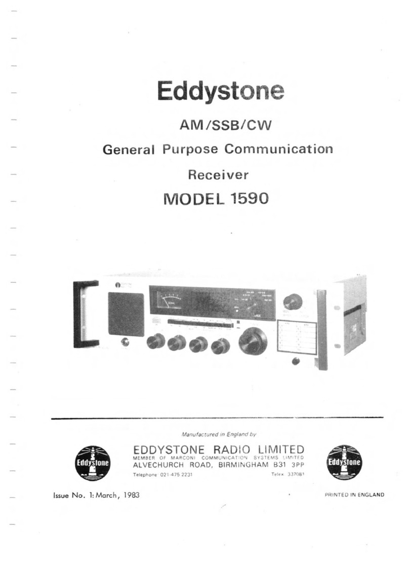
Eddystone 990R User manual

IBDYSTONE RADIO LTD
ALVECHURCH ROAD
BIRMINGHAM 31

EDDYSTOHE VHP RECEIVER
MODEL 99QR
The EDDYSTOHE Model 990R is afully transistorised single-conversion superhet for
CW, AM and Fid reception in the VHF band 27-240 MHz. It is suitable for use over the
temperature range 0-50°C and can be supplied with amatching panoramic display unit
when visual signal analysis is an additional requirement. Operating voltage can be
either 12V DC or any standard AC supply.
Advanced circuit techniques are employed throughout, performance is of ahigh order
and the design will be found suited to many varied applications including normal comm-
unications work, interference checking and noise measurement. Field use is facilitated
by the ability to operate direct from low-voltage supplies with low current drain.
The complete tuning range is covered in four switched bands which give adequate
bandspread even at the higher frequencies. Local oscillator arrangements permit oper-
ation with crystal control (up to eight switched channels), external frequency control
or normal continuous tuning. Selectable bandwidths of 30 kHz and 200 kHz are provided,
using acrystal filter in the narrow position. Alternative crystal filters are avail-
able to order when other bandwidths are required.
Two separate outputs are available from the 10.7 MHz intermediate frequency channel.
The first is alow-level wide-band output (also usable as IF Input) and is mainly
intended for driving the companion Panoramic Display Unit (Model EP17R) via an external
IF Converter. Bandwidth at this output is of the order 1MHz at the higher frequencies
in the tuning range. The other output is taken from the final stage in the IF Channel,
bandwidth being determined by the setting of the panel selectivity switch. Video out-
put is available on both AM and Fid.
Audio facilities include outputs for external speaker, telephones and remote lines,
the latter being restricted to permit direct connection to Post Office circuits. A
separate level control is used for the line amplifier which is totally independent of
the local monitor channel. Frequency response is maintained within 6dB up to 10 kHz
and abuilt-in monitor speaker is fitted for convenience in rack-mounted installations.
Other standard features include an internal crystal calibrator (modulated 10 MHz
markers), atuning meter and acarrier-controlled muting system. Panel controls
comprise Tuning (gear-drive, flywheel-loaded with aratio of approximately 100 si),
Range Switch, System Switch (NOIvMAL -CRYSTAL -EXT OSC), and acombined Mode/Supply
Switch. Separate switches are provided for Selectivity, AGC, Muting, Calibrator and
Monitor Speaker? amechanical cursor shift is fitted for correcting scale errors when
calibrating. Pre-set Line Level, Meter Zero and Muting controls are located at the
rear of the set together with aminiature toggle switch for closing down the front-end
converter when using the IF Input facility.
The receiver is equally suited to bench or rack-mounting and though weighing less
than 20 lb is extremely robust constructionally. Printed wiring techniques are employed
for most parts of the circuit, using high-grade components throughout. Internal layout
is arranged for easy access in the event of servicing being necessary. External appear-
ance is in keeping with modem trends and finish is to the highest standard.
Sole Manufacturers s-EDDYSTOHE RADIO LIMITED ,ALVSCHURCH ROAD, BIRMINGHAM 31, ENC-LAHD.
Issue 1.August 1967 .

LIST OP CONTENTS
Section
Technical Lata ....«»•94«
Page
3
Circuit Description . . . . »«A900©A5
Mechanical Construction ....0 0 9990©e12
Installation ....»o990A•A13
Operation .. . . • 9 »9oa©018
Maintenance ....et» »o0o©025
Appendices
Appendix "A" Voltage Analysis 99•9 9 9ft 033
Appendix "B" List of Component Values 9O999•ft 935
Appendix "C" List of Spares 99«e«9ft 943
Appendix "D" IP Converter Type 959 9a9• A 9ft 048
Illustrations
Circuit Diagram of IP Converter Type 959 «9a•9«949
Plan View of 990R Receiver 9999*9950
Underside View of 990R Receiver '
9» 9 9 • 9 951
Internal Layout % s Crystal Oscillator Unit 9A9999952
Internal Layout ssIP Pre-Amp/Pilter Unit 9•»99a952
Block Diagram of 990R Receiver •99O9 « Rear cover
Circuit Diagram of 990R Receiver o o •A9 9 Rear cover
amenment record
Amend .No
•
Incorporated by
i
Date
i
'
2
3
4
5
6
7
8
9
10 1
;
Amend. No. Incorporated by Date
11
12
13
14
15
16
17
18
19
20
Eddystone Radio Limited reserve the right to amend this publication. Amendment Sheets
will be incorporated where necessary at date of issue.
-2-

TECHNICAL LATA
GENERAL
Intermediate Frequency .
10.7 MHz-
Power Supply .
Single-phase AC mains 100/130 and 200/260V
(40-60 Hz) or 12V LC.
Transistor Complement -(WB% Equivalent types may be used where necessary)
Ref Type Manufacturer Circuit Function
TR1 AF239 Siemens RP Amplifier.
TR2 AF239 Siemens Mixer.
TR3 AF239 Siemens Local Oscillator 1* (VFO)
TR4 GM290 Texas Frequency Multiplier.
TR5 GM290 Texas Local Oscillator 2. (CRYSTAL)
TR6 GM290 Texas Crystal Oscillator Isolator.
TR7 GM290 Texas External Oscillator Isolator. .
TR8 GM378 Texas Crystal Calibrator.
TR9 GET880 Mullard Tone Modulator.
TRIO GM290 Texas IF Pre-amplifier.
TR11 GM290 Texas Narrow Filter Input Switch.
TR12 GM378 Texas Narrow Filter Output Switch.
TR13 GM290 Texas Wide Filter Input Switch.
TR14 GM378 Texas Wide Filter Output Switch.
TR15 GM378 Texas IF Amplifier.
TR16 0/1378 Texas IF Amplifier. •
TR17 cm Fairchild IP Amplifier.
TR18 GM290 Texas Emitter Follower 1. (IP OUTPUT)
TR18A GM290 Texas Emitter Follower 2. (FM ISOLATOR)
TR19 GM290 Texas FM Limiter Driver.
TR20 GM290 Texas FM Limiter.
TR21 ASY29 Mullard RF AGC Amplifier.
TR22 ASY29 Mullard IF AGC Amplifier.
TR23 GM378 Texas Beat Frequency Oscillator.
TR24 GM378 Texas }CW Detector.
TR25 GH378 Texas j
TR26 GET880 Mullard 1st Noise- Amplifier.
TR27 GET880 Mullard 2nd Noise Amplifier.
TR28
TR29 2N3704
2N3704 Texas 1
Texas jRelay Trigger (Muting)
.
TR30 GM378 Texas Video Amplifier (l).
TR31 GM378 Texas jVideo Amplifier (2).
TR32 GET880 Mullard
|^Amplifier. )6000 Channel
TR33 OC72 Mullard AF Output ,7
TR34 GET880 Mullard AF Amplifier, i
TR35 AC127 Mullard AF Amplifier. 1
TR36 AC128 Mullard AF Driver. i30 Channel.
TR37 !AC127 Mullard 7iComplementary j
TR38 !AC128 Mullard J
1
!AF Output. )
av-rA 2S5\0^ w\a~^ he in b-e«A $4 c^r<( C\\\ n.
-3-(
Frequency Coverage .
27-240 KHz in four ranges.
Range 1
Range 2
Range 3
Range 4
130
75 -
46 -
24Oiffiz
130 MHz
76 Mz
(Nominal)
.
(Nominal)
.
(Nominal)
*
27 -46 Mz (Nominal).

Other Semiconductor Devices (etc.)
Ref Type Manufacturer Circuit Function
D1 9At\k> MulWd Overload Protection Diode.
D2 OA47 Mullard Response Correction Diode.
D3 0A47 Mallard AM Detector.
D4/5 OA79 Mullard FM Discriminator.
D6 BZY88* Mullard. RF AGC Delay. *C6V8
D7 OA47 Mullard RF AGC Rectifier.
D8 !OA47 1Mullard IF AGC Rectifier.
D9/10 0A202 Mullard Uoise Rectifier.
Dll 0AZ228 Mullard 10V Supply Regulator.
D12 DD006 Lucas Reverse Polarity Protection.
D13 0AZ230 Mullard 12V Supply Regulator,
D14 M160T G.E.C. Supply Rectifier.
1—
Input and Output Impedances .
Aerial Input 75Q unbalanced (BNC).
Ext Osc Input ,Low-impedance (bnc)
.
IF Output 1* ,Low-impedance (BNC).
IF Output 2** ..Low-impedance (bnc)
.
Video Output iooon (bnc).
Audio Output .Loudspeaker s30.
*wide band.
** narrow band
Lines s600Q.
Headset sLow-Z*
IF Output 1also usable as 10. 7MHz Input
.
TYPICAL PERFQffilANCE
Noise Factor .
Of the order lOdB.
Sensitivity.
5(iV for lOdB s/n ratio with 50mW output in
AM mode with selectivity at NARROW posn
(50 kHz filter).
Spurious Response .Deviation .
50dB down. Up to 75 kHz.
Calibration Accuracy .
Within 1fo. Crystal-controlled markers are
available at 10 MHz intervals.
Prequency Stability.
So
1part in lCr per Cchange in ambienjfc
temperature. Of the order 1part in 10
per °C with crystal control.
IF Bandwidth ,
30 kHz (crystal filter) and 200 kHz.
AGO Characteristic .
The audio output level does not change hy
more than lOdB for an increase in input of
80dB above 10pV.
Audio Output .
The 30 loudspeaker output provides amax-
imum output power of 500mW at 10Jo distor-
tion.
Line output is restricted to lOmW.
Audio Response .
Level within 6dB from 200 Hz to 10 kHz.
IF Output .
An output of the order 50mV is available
from the IF Output 2socket. This is
suitable for driving the EP17RPanoramic
Display Unit for bandwidths up to 200 kHz.
IF Output 1provides alow-level output at
greater bandwidth on the higher frequency
ranges
.
Video Output and Response .
Output is of the order 1volt p-p into a
10000 load. Video response is 6dB down at
20 Hz and 100 kHz with external loading of
250pF.
IF Converter Type 939 °(See Appendix nDn)
Output at 5*2 MHz is substantially the
same as the input drive from the 990R
receiver. The converter is crystal-
controlled and has afixed bandwidth of
1MHz.

CIRCUIT D E SCRIPTION
THE RE SECTION
General
.
This portion of the receiver employs ahigh-gain RF Amplifier (TRl), alow-noise
Mixer (TR2) and acomprehensive Local Oscillator system utilising atotal of five
transistors (TR5-TR7). An associated circuit is the Crystal Calibrator which uses two
transistors (TR8 &TR9)
.
The whole Section is sub-divided into three parts ;TR1-TR4 being housed in the RF
Tuner Unit and TR5-TR7 in aseparate screened enclosure .TR8 and TR9 are located in a
further screened housing mounted on top of the RF Tuner Unit.
The five stages in the Local Oscillator system provide for continuous tuning over
the whole coverage, spot frequency working on up to eight switch-selected crystal-
controlled channels, or (semi-) continuous coverage using external synthesised drive
when high-stability operation with flexibility of frequency selection is arequirement.
The method of oscillator control is selected by the SYSTEM SWITCH (SJA-U) which also
serves as "crystal-selector15 .Local Oscillator injection is always higher than the
received signal frequency (10.7 MHz i*f»).
The RF and Mixer Stages .(TR1 &TR2)
Both the RF Stage (TRl) and the Mixer Stage (TR2) employ AF239 germanium mesa trans-
istors. TR1 is operated as agrounded-base amplifier with manual or automatic gain
control selected by one section of the MANUAL/AGC SWITCH (S6A) .Gain control is not
applied to the Mixer Stage but is applied to the IF Pre-amplifier TRIO which follows
the Mixer. Control is from the same line as the RF Stage, aseparate circuit being
used for the later IF Stages.
Aerial input is taken via SIB to low-impedance taps on the input circuits LI-L4. D1
(MYJU silicon diode) is wired directly across the input to provide some measure of
protection for TRl when using the receiver in close proximity to ahigh-power trans-
mitter. The emitter of TRl is fed via SID and CIO from separate low-impedance windings
on the input tuned circuits. All unselected main windings are shorted to ground by SIC
which also connects the aerial section of the 4-gang tuning capacitor to the selected
circuit. Separate trimming capacitors are provided for all circuits, those for Range 1
being directly across the tuning capacitor and therefore in circuit on all ranges.
Coupling to the Mixer Stage (TR2) is by atuned bandpass circuit with low-impedance
link coupling between primary and secondary. The collector of TRl is matched to the
primary by tapping down the appropriate coils (L5-L8), while separate coupling windings
are provided on LI0—D12 to match the base of the Mixer Stage. Unused circuits are
shorted as on the input stage and the two sections of the tuning capacitor (C1 3 6c C23)
are switched from range to range by S1F and S1G.
Oscillator injection is to the emitter of TR2 via C45, regardless of the oscillator
arrangements in use. Atwo-stage low-pass filter is included in the IF feed to T1
which has alow-impedance secondary for connection to the IF Pre-amplifier. Connection
is to SK5? the primary of T1 being timed to 10*7 MHz by the trimmer C30.
S2 provides ameans of disabling the Mixer Stage to prevent noise and signal break-
through when using SK10 as an IF input connection.
S1A switches aset of four indicator lamps (lLPl-4) to show which range is in use.
The lamps are situated at the left-hand end of the appropriate range marking on the
scale plate. All RANGE SWITCH wafers have five positions but are fitted with amech-
anical stop to prevent selection of the fifth position.

Local Oscillator Circuits .(TR3-TR7
)
Germanium epitaxial mesa transistors (GM290) are used for all stages except TR3
which employs afurther AF239. TR3 &TR4are located in the RF Tuner Unit.
TR3 is the normal Local Oscillator for continuous tuning and is tuned by the fourth
section of the tunihg gang (C40 ), Output voltage is developed across the earth return
inductance from the tuned circuits which is marked "Z" on the circuit diagram. TR3 is
functional with the SYSTEM SWITCH S3 at "NORMAL" and is disabled in the other positions
by removal of the emitter supply voltage. Base voltage is retained at all times.
The remaining transistor located in the RF Tuner Unit is TR4. Its function is to
facilitate connection to the normal oscillator tuned circuits (via the isolating
resistor R17) from the alternative oscillator input at SK6.Operating conditions are
such that TR4will function as afrequency multiplier when required, multiplication by
factors of two or three being possible with normal drive levels. Oscillator circuits
L13-L16 offer some measure of protection against spurious drive signals especially when
using the receiver with external synthesised drive.
TR4is switched by interrupting the emitter supply at S3 when this is set to the
"NORMAL" position. Base voltage is retained as on TR3
.
The miniature socket SK6located on the RF Tuner Unit is fed via PL3 which termin-
ates ashort coaxial lead from TR6and TR7 in the separate Crystal Oscillator Unit.
Both these transistors are used as emitter followers and serve to isolate the separate
feeds from the internal crystal oscillator and the external oscillator drive source.
The Crystal Oscillator (TR5) employs aseries-mode circuit with output taken from
the collector via C56 .Up to eight crystals can be fitted at any one time, separate
tuned circuits being provided to permit accurate alignment of the oscillator circuit to
suit the crystal in use. The tuned circuits are adjusted when installing the crystals
and allow slight pulling of the crystal to bring the appropriate signal channel into
the centre of the i.f. passband. All circuits are identical and have values to suit
crystals in the basic range 37-88 MHz.
Actual crystal frequencies are calculated from (fs +10. 7), l/2(fs +10. 7)or
l/3(fs +10.7) MHzdepending on the part of the overall range in which the selected
signal frequency falls. Detailed information on calculation of crystal frequencies for
specific signal channels will be found on page 22 in the Section on "Operation".
Oscillator drive from the Crystal Oscillator is applied to the base of TR6 which
provides alow-impedance output to feed the alternative oscillator socket SK6 via PL3.
External oscillator drive is introduced to the Crystal Oscillator Unit via SK7 which
is linked to aBNC socket at the rear of the set by ashort length of coaxial cable
terminating in PL4. Input level should be of the order 500mV, isolation being provided
by the other emitter follower TR7 which feeds SK6 via PL3 and C60.
Switching of TR5, TH6 and TR7 is by S3C &S3D. Base and emitter supplies are re-
moved from TR5 except when S3 is set to one of the eight "CRYSTAL" positions. Base
voltage remains on the two emitter followers (TR6 &TR7) except at "NORMAL" when all
supplies are removed from the Crystal Oscillator Unit. The emitter voltages for TR6
and TR7 are applied only in the appropriate positions, i.e. to TR6 at "CRYSTAL" and to
TR7 at "EXT (OSC)".
Crystal Calibrator .(TR8 &TR9)
The crystal-controlled calibration oscillator (TR8 sGM378 )and its associated Tone
Oscillator/Modulator (TR9 sGET880) provide crystal check-points at 10 MHz intervals
throughout the tuning range of the receiver. Injection is to the primary of the inter-
stage coupling between RF Amplifier and Mixer by asmall probe attached to SK4. This
is fed from the Calibrator via ashort length of coaxial cable terminating in PL5.
-6-

The Calibrator is brought into operation by means of S4 which completes the +10V
supply via R37 to both TR8 &TR9- Correction for scale errors is carried out mechanic-
ally with an adjustor which provides limited lateral movement of the cursor independ-
ently of the TUNING CONTROL,
Calibration checks can be carried out in any position of the MODE SWITCH, greatest
accuracv being obtained either at "CW" where the receiver can be tuned to zero-beat
with the Beat Oscillator crystal, or at "Mi" whore the centre-zero tuning meter can be
used to advantage. Checks should be made with the SELECTIVITf SWITCH at NAltrfO 1.
THE IF SECTION
General .
The standard intermediate frequency of 10.7 MHz is employed in the IF Section which
provides detection facilities for AM, F1VI, CW and video reception. Two IF bandwidths
are available selected by apanel control.
Associated circuitry, including the AGC system, muting circuits and video amplifiers
will be considered in this Section.
IF Pre-amplifier and Filter Unit .(TR10-TR14)
IF output from the Mixer Stage is fed via PL7 and ashort length of coaxial cable to
the base of the IF Pre-amplifier (TRIO 1GM2$)0) which is one of five transistors
located in the IF Pre-amplifier/Filter Unit at the rear of the RF Tuner Unit. The
four remaining transistors (TRII-TRI4)are operated in the emitter follower configura-
tion and serve as switches to select input and output of the two lx1Filters. Only
three of the five transistors in this unit will be functional at any time.
The IF Pre-amplifier utilises the common emitter configuration with its base tied to
the RF Amplifier manual/auto gain control line via FC5. Signal output is taken via C77
and C83 to feed both the input switches in parallel from atap on T2.
TR11 (GM290) and TR12 (GM378) switch the input and output respectively of the
crystal filter used in the "NARROW" selectivity position. Overall bandwidth is 30 kHz
at 6dB down. C78 and C79 allow accurate matching to the input and output of the
crystal filter.
An L/C filter comprising TJ ,T4and T5 is used in the other leg 9inpub being
switched by TR13 (GM290) and output by TR14 (GM378). Bandwidth on this channel is
200 kHz (SELECTIVITY SWITCH at "WIDE").
Selection of the appropriate input and output "switch" is by S5A and S5B, the former
removing base and emitter voltage from the input switch on the inoperative channel, the
latter removing base and emitter voltage from the output switch.
The +10V supply is also applied via S5B and R47 to D2 (0A47 )inthe "WIDE" position
to damp the crystal filter and suppress minor distortion of the 200 kHz response which
would otherwise occur due to stray coupling through TR12. C80 completes the diode
circuit for i.f. voltages.
Provision is made in the form of SK10 for direct connection to the input of the IF
Pre-amp (TRIO) when it is desired to use the 10. 7MHz IF Stages to amplify an
externally derived signal at this frequency. An external converter with IF 0/Pat
10 7MHz could easilv be connected at this point to extend the tuning coverage of the
receiver proper. S2allows the normal RF Tuner Unit to be shut down to prevent noise
and signal breakthrough from the main channel
.
SK10 can also be used to extract alow-level output at 10.7 MHz for connection to
external ancillary equipment (panoramic display etc.). Bandwidth is of the order 1iv z
at the higher frequencies in the tuning range.
-7-

Main IF Board .
Output from the IF Pre-amp/Filter Unit is taken via ashort coaxial cable to the
large printed board which carries the greater part of the IF circuitry* Separate
branches are provided for AM and FM, the AM branch also feeding aproduct detector for
CW reception. This particular circuit is in ascreened housing, as also are the two
emitter followers TRIG and TR13A.
AM Stages and IF Output .(TR15-TR18)
Three stages of amplification are provided in the form of TR15 (GM'378) ,TR16 (GM378)
and TR17 (2S512), the latter being an n-p-n silicon epitaxial planar transistor.
TR15 and TR16 operate with manual or automatic gain control dependent on the setting
of the MANUAL/AGC SWITCH S6. The control line is separate from that which feeds the
RF and IP Pre-amp Stages 5it is switched by S6B.
All three IP Stages operate in grounded-emitter mode, inter-stage coupling in each
case being single-tuned circuits (T6 &T7) tapped to feed the base of the following
stage. Atuned-secondary transformer (T8) is used to feed the AM/Video Detector D3
(OA47)» This stage has awide frequency response and its output is tapped down the
diode load to increase the dynamic range of the following stage. R79/C119 form anormal
IP filter feeding the "AM" position of the MODE SWITCH wafer S7B.
Atap on the secondary of T8 is used to drive the emitter follower TR18 (GM290)
which provides alow-impedance 10. 7MHz output at SK11 (BNC socket). Output level is
of the order 25mY across 750 for an aerial input of lOfiV. Bandwidth is determined by
the setting of the panel SELECTIVITY SWITCH being ei ther 30 kHz or 200 kHz overall.
The IP output is available continuously regardless of the MODE SWITCH setting.
CW Detector Unit .(TR23-TR25)
IP signal is taken from the collector of the final IP Amplifier (TRI7) to feed the
CW Detector via R76/C159*
The Detector proper comprises TR24 and TR25 (2 xGM378), signal at IP being applied
to the base of TR25 and BPO voltage to the base of TR24* The Beat Oscillator (TH23 %
GM378) is crystal controlled at 10.7 MHz and delivers output to the base of TR24 from
its emitter via C157*
The collectors of the two detector transistors are linked together and work into a
common load (R12l) from which output is taken via the filter CH2l/Cl60 and the output
capacitor Cl6l to the "CW" position of S7B. The +10V supply is applied to all three
transistors via R124 and CH22 by S7A when set to "CW". Extensive filtering and total
screening of the complete unit prevent harmonics of the 10. 7MHz oscillator appearing
in the tuning range of the receiver.
FT! Channel .(TR18A, TR19 &TR20)
In addition to feeding the two final amplifiers on the "Ah" path, TR15 also feeds
TR18A which provides isolation for the FLi Stages. TR18A is wired as an emitter
follower and coupled to the Fj'I Limiter Driver Stage (TR19 sGLI290) by C123A and C125.
The PM Limiter (TR20 sGM290) is fed from the previous stage through adouble-tuned
transformer (T9) with tapped secondary to match the base impedance. Both TR19 and TR20
employ common-emitter configuration.
The Discriminator uses apair of OA79 diodes (D4/D5) in aconventional Foster-Seeley
circuit, component values etc. being chosen to preserve the overall response.
Output is taken via CHI8to the "PM" position of the MODE SWITCH
wafer S7B. Afurther output is provided via R126 to drive the Noise Amplifiers in the
carrier-controlled muting circuit. The +10V supply is permanently connected to the- PM
Stages
.
-8-

Video Amplifier .(TR30 &TRJl)
Audio/video output from the "AM”, 11 CW" and "PM” positions of S7B is fed to the base
of TR30 (GM378) which serves the dual purpose of audio amplifier and emitter follower
to feed the main Video Amplifier, Audio output is fed via low-pass filter CI76/CH27/
C177 to the Audio Section which is described later (page 10).
Video response is maintained at the emitter of TR30 which is then direct-coupled to
the base of TR31 (GM378). The low frequency response in this stage is effectively
boosted by applying considerable high-frequency attenuation in the form of C178.
Video output is developed across R149 and connected to SKI2(BNC socket) via ashort
coaxial lead.
The complete video circuit is on aseparate printed board mounted at the rear of the
set and is operative in all positions of the MODE SWITCH, drive being derived from the
selected detector via S7B.
AGO Circuits and Manual RP/lF Gain Control ,(TR21 &TR22)
Separate manual gain controls and AGO circuits are provided for the RF Stage
(together with the IP Pre-amp) and the IP Stages. The desired mode of operation is
selected by the MANQAL/AGC SWITCH (S6) which routes the base returns of the various
stages to the appropriate parts of the circuit. ’’Forward” AGC is employed.
In the case of manual operation, the transistors are returned to the sliders of two
potentiometers (RV1 and RV3) wired directly across the 10V supply. Both potentiometers
are combined in one assembly with concentric controls. Gain is reduced when the
sliders move towards the negative end of the tracks. Both manual gain controls are
switched out of circuit and are totally inoperative when using AGC.
The AGC system comprises two separate AGC Rectifiers (D7 and D8) with associated DC
Amplifiers TR21 and TR22 (2 xASY29)* The diodes, which are fed from the final IP Amp-
lifier (TR17) via C144 and C145? drive the bases of the DC Amplifiers more positive on
receipt of a signal, thus causing their collector currents to increase (n-p-n transis-
tors). Initial no-signal collector currents are set by RV5 and RV6 to produce
identical control voltages on the AGC line to those obtained with the manual controls
at their maximum settings. Gain of the RP AGC Amplifier is controlled by RV2.
Some measure of delay is introduced on the RP AGC line by virtue of the zener diode
D6 which holds the voltage constant at low signal levels. As the signal increases in
strength, voltage developed across R97 becomes greater, the zener diode loses control
and the line voltage then varies in sympathy with the signal. This refinement helps
maintain optimum signal/noise performance by shutting down the IP Section in advance of
the earlier stages.
Meter Circuit .
Asensitive centre-zero micro-ammeter is fitted for relative carrier level measure-
ment and is also usable as atuning indicator. Scaling is in arbitrary divisions 0-10.
The meter operates from the IP AGC line at ”CW” or "AM" and from the output of the
Discriminator at "FM" ,switching being achieved automatically with change of mode (S7C
and S7D). Series resistors (R108 and R125) prevent loading of the associated circuits
and arrange the meter sensitivity to suit the available voltage. At "CW" and "AM”, the
meter is returned via S7D to apre-set METER ZERO CONTROL (RV4) which allows the meter
needle to be biased electrically to anormal left-hand zero against the standing "no-
signal” potential across R106. In these two modes, the meter presentation is logarith-
mic with the MANUAL/AGC SWITCH at "AGC” and linear (up to the threshold of overload)
with the switch in the "MIAL" position. Normal centre-zero operation is employed in
the "PM” mode, the meter being returned directly to earth through S7D.
-9-

Muting Circuit .(TR26-TR29)
Noise voltages at the output of the PM Discriminator (in the absence of asignal)
are passed via ahigh-pass filter to the two-stage Noise Amplifier comprising TR26 and
TR27 (2 xGET880) .Circuit constants are chosen to give maximum amplification at
frequencies above the speech and music range, RV7 provides ameans of setting the gain
of TR26/TR27, while TH1 ensures sensibly consistent performance with changes in ambient
temperature
.
The second of the two Noise Amplifiers feeds avoltage-doubler Noise Rectifier
(D9/D10 12x0A202 )via a(vinkor) transformer tuned to approximately 27 kHz by C170.
The output, load of this stage (R135) is in series with the base return of TR28 (2N3704)
which is the input stage of aSchmitt Trigger.
With the MUTING SWITCH (S8) in the "ON" position, all transistors in the muting
circuit are operative and anegative voltage is produced across R135 in the absence of
areceived. 'signal (i »e•under noise conditions). This puts TR28 in the '’off" condition
•and so causes TR29 (2N3704) to conduct heavily due to the reduced voltage drop in R140.
The. relay RLA/2 is energised and audio output to both line and speaker cut by contacts
A1 and A2 (See "Audio Section" below)
.
On receipt of asignal, noise voltages are removed from TR26/27, the voltage across
R135 falls rapidly to zero and TR29 is tripped into the "off" condition by the increase
in current through R140. RLA/2 falls out, restoring audio output and also opening the
circuit across the MUTE INDICATOR terminals at the rear of the set.
THE_AUDIO_SECTION
General .
Audio from TR30 on the Video Board is routed to two separate gain controls (RV8 %
AUDIO GAIN and RV9 1LINE LEVEL) which feed the two independent audio channels. Both
amplifiers are usable simultaneously in any mode of operation and provide separate out-
puts for local and remote use.
Relay contacts A1 and A2 are arranged to mute both channels in the absence of a
signal when the muting facility is being used. A1 short-circuits the 6000 line output,
while A2 open-circuits all local monitor outputs and closes the circuit between the two
MUTE INDICATOR terminals. Aremoto lamp can be controlled by thi» circuit to indicate
that the receiver is operational but in the muted condition. Aseparate lamp supply is
required.
Low-level Audio Channel .(TR32 &TR33)
TR32 (GET880) and TR33 (OC72) form alow-level audio amplifier for connection to
6000 line circuits. Gain adjustment is by RV9 which is apre-set control! maximum out-
put is limited to lOmW. The output transformer (T12) has acentre- tapped secondary and
is electrostatically screened from the primary winding. Output can be arranged to suit
balanced or unbalanced lines.
High-level Audio Channel .(TR34-TR38)
This amplifier employs atotal of five transistors (TR34-TR38) and provides output
for an external loudspeaker, an internal low-level monitor speaker and low-impedance
telephones (headset). The monitor speaker can be switched off by S9 and the external
speaker by insertion of the telephone plug at JK1.
THa high-level audio stages operate from a
+12V supply line.
-10-

POWER SUPPLY
General .
This part of the receiver is of conventional design and allows operation from any
standard AC supply or 12V DC.
AC Operation .
In the case of AC working, afull-wave selenium low-voltage bridge rectifier is
fed from the low-voltage secondary -winding (14V) on TI4.Tappings are provided on the
split primary windings to allow adjustment for the local mains voltage. Zener diode
D13 (0AZ23O) regulates the output from the rectifier at 12V to feed the high-level
audio stages }ci^cu\4s^ ?OV ze^or circle *
DC Operation .
For DC working, the shorting plug (PL8) is removed from SK13 to isolate the 12V
zener diode and the AC transformer. Connection of the external 12V supply is then by
PL9, the 10V line being regulated in the normal manner by the 0AZ228.
Fusing and Protection.
FS1 fuses the negative 12V supply line and is wired to be in circuit for both DC and
AC operation. On AC, an additional fuse (FS2) is included in the live line to the
power transformer primary. Switching is by S10A and SlOB which interrupt both the AC
and DC circuits in the "off" position. S10 is ganged to the MODE SWITCH S7*
Asilicon diode (D12 sDD006) is wired directly across the 12V input and serves as a
protection device in the event of the supply being connected with reversed polarity.
If this occurs, D12 conducts in aforward direction and draws acurrent which exceeds
the rating of FS1. The fuse fails and isolates the receiver from the supply.
-11-

MECHANICAL CONSTRUCTION
General .
The 990R Receiver in its standard form is suitable for bench-mounting only. Rubber
feet are fitted to raise the controls into aconvenient operating position. Receivers
are available for rack-mounting and are designated Model 99OR/RM. Dimensions and
fixing are arranged to suit standard 19-inch Post Office racking. Conversion kits can
be supplied to allow conversion of standard receivers already in service. Ashock-
absorbent mounting is available if required.
Dimensions.
19s- lb. (8.8 kg.)
20 lb. (9 kg.)
Internal Layout .
Printed wiring techniques are employed throughout with the exception of the Power
Supply Unit which is built on asmall metal sub—chassis located at the rear of the set
adjacent to the IP Pre-amp./ Filter Unit in the rear right-hand corner. The various
printed boards employed are as follows s
-
1. RP TUNER UNIT (TRI-TR4) .One main board plus four small boards carrying the coils
and trimmers for the various stages.
2. CRYSTAL OSCILLATOR UNIT (TR5-TR7 ).One main board plus one small board carrying the
coils and trimmers in the Crystal Oscillator Stage. The crystal holders are mounted
on the main board and are accessible after removing the rear cover.
3. CRYSTAL CALIBRATOR UNIT (TR8 &TR9) •Mounted on top of RP Tuner Unit.
4. IF PRE-AMP ./FILTER UNIT (TR10-TR14) .Access is through aremovable cover in the
right-hand side-plate
.
8. MAIN IP BOARD (TR15-TR29). The two Emitter Follower Units (TR13 &TR18A) and the
CW Detector/BFO Unit (TR23-TR25) are in separate screened assemblies and are mounted
directly onto the main board.
6. VIDEO AMPLIFIER (TR30 &TR3l).
7. LOW-LEVEL AUDIO AMPLIFIER (TRJ2 &TR33).
8. HIGH-LEVEL AUDIO AMPLIFIER (TR34-TH38).
-12-
7Separate boards located at rear
jof receiver
.
Weight *
Bench-mounting version
Rack-mounting version

Panel.
The front panel is alight-weight aluminium casting and contributes groat mechanical
strength to the receiver as awhole. Chromium-plated handles are fitted for con-
venience in handling the receiver and these also allow it to be placed "face-down”
without damage to the panel controls when removing the cabinet.
Cabinet .
This is fabricated from light-gauge sheet steel and affords adequate protection for
the receiver regardless of the manner in which it is mounted. Fixing points are pro-
vided in the form of hank bushes for attachment of rack-mounting brackets, rubber feet
and shock-absorbent mountings.
Dial and Drive Assembly .
The tuning control drives aspring-loaded split-gear system having areduction ratio
of approximately 100 s1.The drive is flywheel-loaded, substantially free from backlash
and ensures aconsistently high degree of re- setting accuracy when use is made of the
logging scales provided. Tuning scales are over nine-inches long and are calibrated
directly in frequency. Acursor adjuster allows correction for scale errors.
External Wiring.
All external wiring (with the exception of the telephone output) is taken to ter-
minals and sockets at the rear of the set. The telephone output is brought out on the
front panel and accepts astandard Post Office jack plug.
INSTALLATION
GENMAL
Accessories .
All receivers are supplied complete with five standard BNC coaxial connectors, a12V
DC supply connector (ready-wired with shorting strap as per PL8 on circuit diagram) and
amains connector with six-feet of three-core PVC lead. Spare fuses (lA and 500mA) are
retained in clips on the right-hand side-plate.
The following accessories and associated equipment are available for use with the
990R receiver s-
1. Rack-mounting conversion kit. (Comprises two rack-mounting brackets t7093? and
four 2BA x§" fixing screws s40A -246)
2. Set of four rubber mounting feet s71J2P. (For use when converting Model 990R/RM to
bench-mounting)
3. Shock-absorbent mounting sLP2817« (Complete assembly for attachment to either
version of the receiver)
4. Cabinet loudspeaker sCat. No. 935*
5. Plinth loudspeaker unit sCat. No. 906.
6. IF Converter Type 959 (959/l for rack installation),
7* Panoramic Display Unit Model EP17R (EPI7R/RM for rack installation).
8. Low-impedance telephones %Cat. No. LP2924*
Orders and enquiries relating to accessories for the 990R receiver should be sent to
the "Sales &Service Dept," at our usual address.
-13-

Converting astandard 990R receiver to rack-mounting .
This is asimple operation taking only afew minutes to complete. Ascrewdriver is
the only tool required.
1.Remove rubber mounting feet and store (with screws) for possible future use.
2. Attach rack-mounting brackets to leading edges of cabinet using the four screws
supplied with the kit.
Fitting shock-absorbent mountings to the 990R receiver .
1. Place the- receiver upside down and remove the rubber mounting feet. Store for poss-
ible future use.
2. Take the large neoprene washers and place these over the fixing holes in the under-
side of the cabinet (stepped face uppermost).
3.Lower the channel- shaped mounting brackets onto the washers, keeping the fixing
flange towards the outside of the receiver and at the same time making sure that the
step on the washers locates with the holes in the brackets.
4.Place the smaller neoprene washers on the inside of the channel and pass the 2BA
screws with brass washers through both neoprene washers.
5.Locate screws in hank-bushes in cabinet and tighten.
6.Fix channel mounting brackets to bench top with suitable screws. Take care to bond
the brackets to the bench top if this is of metal construction.
Panoramic Display Installation Type EPR30 .
The 990R receiver can be supplied as apanoramic display installation which com-
prises the following items and is designated Model EPR30 (EPR30/RM rack-mounting).
1.990Rreceiver (99®/^) •
2. EP17R Panoramic Display Unit (or EPITR/RM) •
3.959 IF Converter (or 959/l) •(10»7 MHz in, 5*2- MHz out).
4.Loudspeaker Unit (bench-mounted version only).
5.Pair of tie-bars for bench-mounted installation.
6.Associated cabling and connectors.
Assembly of EPR30 Panoramic Display Installation .
1. Invert receiver and remove the four rubber feet (if fitted). Attach loudspeaker
unit to underside of receiver vising the four screws provided. Do not use the screws
which previously held the rubber feet .
2. Connect the loudspeaker lead to the 30 terminals at the rear of the receiver.
3. Place receiver in aface-down position and remove the four cabinet retaining screws.
Fit the two tie-bars to the receiver, omitting at this stage the top retaining screw
on the left-hand bar (adjacent to aerial input socket). Fit spacing washer on the
bottom left-hand screw. Set receiver down resting on its plinth speaker unit.
4.Remove the four cabinet retaining screws from the EP17R Display Unit and place it on
top of the receiver. Re-fit three of the screws through the tie-bars (spacing wash-
er on top left-hand screw) .Omit screw in lower left-hand corner.
5.Slacken the two screws in the left-hand tie-bar and slide the 959 IF Converter
mounting bracket between the tie-bar and the rear of the main units so that the two
holes in the bracket coincide with the two centre fixing holes in the bar. Fit the
two screws omitted in operations (3) and (4) above. Tighten all screws securely.
6.Connect the receiver IF Output socket to the Input socket on the 959 Converter and
the IF Output socket on the IF Converter to the Input socket on the Display Unit,
using the leads provided. Plug the 959 IP Converter supply connector into the 12V
supply socket on the receiver after removing the existing shorting plug.
7.Make "all other external connections as for normal receiver installation as des-
cribed later in this Section.
-14-

Assembly of EPR30/RM Panoramic Display Installation .
1. Remove rubber feel from receiver and display unit (if fitted)*
2. Mount receiver and display unit in rack with, receiver in lower position.
3. Attach IF Converter Type 959/l to rear of equipment. Refer to sheet supplied.
4. Make connections as per paras (6) and (7) for bench-mounted installation.
NB Use IF OUTPUT (l) for wide-band presentation.
11AI1TS_Y0LTAGE_ADJUSTMMT
The voltage tappings on the primary side of the power transformer must be checked
and changed if necessary before connecting the receiver to the supply. Tapping points
are located below chassis at the rear of the set and are accessible after removing the
cabinet. The transformer has two separate 130V primaries tapped as follows s-
10V (1) ov (2) 100V (3) 120V (4) DISCONNECT FROM
Rear of set 000OSUPPLY BEFORE
000OADJUSTING TAPS.
*5 10V (6) ov (7) 100V (8) 120V (9)
For voltages in the range 200/260V, operate appropriate sections of secondaries in
series 5for voltages in the range 100/1 30V, operate equal sections of the primaries in
parallel. Tappings (3) or (4) should be linked to (6) or (7) for series working.
The receiver leaves the factory with tappings set for 240V operation.
EXTERNAL CONNECTIONS
Mains Operation.
Asuitable polarised connector and three-core mains lead are supplied with the set.
The lead is colour-coded as follows:- RED 1LIVE, BLACK 1NEUTRAL, GREEN sEARTH.
One end of the lead is left free so that the user can fit aplug of atype suitable for
connection to the local supply.
When operating from AC mains, it is important to check that ashorting plug is in
position at the 12V DC supply socket. Its purpose is to complete the 12V regulated
positive line to the appropriate receiver circuits. The plug should be wired as PL8on
the circuit diagram at the rear of the Manual.
12V DC Operation.(NEGATIVE EARTH ONLY)
If an extended period of operation from 12VDC is envisaged, the existing shorting
plug (which is used in mains operation to complete the 12V supply line) can be re-wired
as shown at PL9 on the circuit diagram. On the other hand, where 12V working is for
emergency operation in the event of mains failure, an additional plug should be ob-
tained to facilitate rapid changeover. The plug is athree-way polarised female
connector Bulgin Type No. P430.
Ancillary Supply .
The 12VDC supply at SK13 is available for connection to external units when the
receiver is operating from AC mains supplies. Maximum available current drain is 35mA.
Note that the negative lead from the external unit must be connected to the earth
terminal and not to SKI3, otherwise FS1 and S10A will be short-circuited if an earth
return exists between the receiver and the ancillary unit.
-15-

Aerial *
The receiver is designed for use with aerials closely matched to 750 and asuitable
BNC connector is supplied to mate with the coaxial aerial socket at the rear of the
set* Low-loss semi-air-spaced feeder cable should be employed especially when oper-
ating at frequencies towards the upper limit of the frequency coverage.
Selection of the best aerial for use with the receiver will depend largely on the
application for which it is to be used and must of necessity be left to the user since
many diverse types are available for use in the frequency band concerned. Reference
should be made to one of the many handbooks dealing specifically with VEF antenna
design.
IF Input and Low-level Output (l) .
BNC termination. Facilitates connection of external converter to extend coverage of
the built-in timer unit (input frequency 10.7 MHz). All control facilities function
as for normal operation with the exception of the TUNING, RANGE SWITCH and SYSTEM
SWITCH. Asmall toggle switch at the rear of the set allows the built-in tuner to be
shut down to prevent signal and noise breakthrough when using the receiver in this
manner
.
The same socket can also be used to extract alow-level signal at 10. 7MHz with
greater bandwidth than is available at the main IF Output socket. Bandwidth is of the
order 1MHz at the higher frequencies in the tuning range and it may well be found
advantageous to drive the associated panoramic display unit from this output in certain
applications. Adequate drive is available for this purpose.
IF Output (2
)
.
BNC termination. Provides output at 10.7 MHz for use with panoramic display or
other ancillary units. Output is of the order 50mV and bandwidth is determined by the
setting of the panel SELECTIVITY SWITCH (either 50 or 200 kHz).
Video Output .
BNC termination. Suitable for external loads of the order 10000. External lead
lengths should be kept to aminimum to preserve the high-frequency response which
extends to 100 kHz with external loading of 250pF. Asmall DC potential of the order
5.5V. is present at this output.
External Oscillator Input .
BNC termination. Permits connection of external oscillator drive to the Mixer Stage
for high- stability working. Basic drive frequency range required is 37-7-250.7 MHz
but the built-in frequency multiplier allows for multiplication by factors of two or
three, so reducing the upper limit to less than 85 MHz. Drive requirement from alow-
impedance source is of the order 5G0mV. The normal oscillator tuning circuits remain
operative and discriminate against spurioiis drive signals in this mode of operation.
External Loudspeaker .
Two terminals are provided for connection of an external loudspeaker. The output is
marked "30" and suitable speakers are available in the Eddystone range. Full details
are available on request.
Telephones .
The telephone output is suitable for use with low-impedance type headsets. Circuit
arrangements provide for muting of the external loudspeaker on insertion of the tele-
phone plug. The Internal speaker can be cut by means of apanel switch.
-16-

Line Output .
This output is marked ”6000" and provides amaximum of lOrnW for connection to remote
lines. The centre-tap (CT) can be left floating: or alternatively earthed to provide a
balanced output. The secondary winding is electrostatically screened from the primary.
It should be noted that this output is short-circuited (in absence of signal) by a
pair of relay contacts when the muting facility is in use. Consideration should there-
fore be given to inclusion of asuitable pad to isolate this output when making direct
connection to Post Office lines.
Mute Indicator .
One pair of contacts on the muting relay is arranged so that the circuit across th$
"MUTE INDICATOR" terminals will be closed when the receiver is running in the muted
condition. The circuit will open (l) on receipt of asignal ,(2) if the muting is
switched to "off", or (3)if the receiver supply is removed.
Alamp (with external supply) can therefore be installed to indicate to adistant
monitoring position that the remote receiver is operational but muted. The lamp will
extinguish on receipt of asignal.
If additional signalling facilities are required, it is asimple matter to replace
the lamp with arelay and use the contacts on this to control other indicators. For
example, aSPDT relay could be arranged to illuminate alamp when the circuit is quiet
and to operate acall buzzer when the channel is in use.
The internal relay contact is wired such that one of the two terminals is permanent-
ly earthed and the other becomes earthed in the absence of asignal (with the MUTING
SWITCH In the "OH" position).
Earth Terminal .
Bond to frame of rack when receiver is installed as arack-mounted equipment.
17-

OPE RATION
22L
I??2L!'2?£^2?§
Tuning *
This control is conveniently located at the right-hand side of the receiver and
operates the ganged tuning capacitors in the RF Tuner Unit through aprecision gear
drive having areduction ratio of the order 100s 1.
Logging scales are provided on the skirt of the control knob and at the foot of the
main tuning dial* Calibration on the latter runs from 0-5000 with index marks at 100-
division intervals. The control knob makes one complete revolution per 100-divisions
of the main scale and is marked 0-100 to permit interpolation between the main scale
markings. All scaling is arbitrary and unlike the frequency scales shows an increase
in reading with movement of the cursor from left to right. Tuning rate varies between
3MHz/rev. and 0*5MHz/rev. at the centres of Range 1and Range 4respectively.
Range Switch .
The RANGE SWITCH is situated immediately to the left of the 'TUNING CONTROL and must
be pushed towards the panel to engage with the gear drive to the switch selector
proper. The panel control is thus isolated from the remainder of the mechanism, a
simple precaution which virtually eliminates any possibility of random frequency change
caused by shocks inadvertently transmitted to the Tuner Unit via the switch mechanism.
.
Range indication is 'provided by alamp display at the left-hand end of the scale
plate. Clockwise rotation of the RANGE SWITCH selects a' higher frequency range.
System Switch .
Selection of the desired mode of local oscillator control is handled' by the SYSTEM
SWITCH. Three modes of operation are possible, vizi-'
1. Manual tuning using the tunable receiver oscillator ("normal” mode marked "N").
2. Fixed freq. working using the crystal controlled receiver oscillator (posns 1-8)
.
3* Operation with external oscillator drive for high- stability applications where
flexibility in frequency adjustment is of prime importance (marked "EXT").
Note that when using modes (2) and (3)above, it is necessary to adjust the TUNING
CONTROL and RANGE SWITCH to ensure that the signal frequency circuits are aligned to
the correct channel. The built-in meter can be used as an aid to accurate tuning.
Mode Switch .
This control combines supply switching (on both AC and DC operation) with selection
of the desired signal mode. The four positions are marked s-
"SUPPLY OFF" -"CW" -"AM" -"EM"
The supply is completed to the receiver by moving to the "CW" position and remains
connected in the other two positions. Illumination of one of the range indicator lamps
will show that the supply is "on".
Mode selection is accomplished by switching the audio outputs of the separate
circuit branches. The supply is disconnected from the CW Detector except at "CW".
Meter switching is afurther associated function performed by the MODE SWITCH. The
meter is arranged to operate with centre-zero for "EM" and normal left-hand zero for
"CW" and "AM" reception. Apre-set zero adjustment is provided for the two latter
modes.
18-

Selectivity Switch ,
Provides ."WIDE" (200 kHz) or "NARROW" (30 kHz -standard) bandwidths to suit recep-
tion mode and signal characteristics. Switching is accomplished "electronically", the
panel switch merely completing power supply circuits to the appropriate switching
stages. Acrystal filter is used for the "NARROW" selectivity position.
NB Alternative filters can be fitted to order in the "NARROW" position only.
RP and IF Gains .
These two controls are combined in one assembly comprising two wirewound potentio-
meters with concentric spindle drives. The smaller control knob (with red index) is
the RP GAIN. Both controls are taken out of circuit and are totally inoperative with
the MANUAL/AGC SWITCH at "AGC"
.
AP Gain Control .
Controls the level of audio at the high-level outputs feeding telephones, internal
speaker and external speaker. Adjustment of this control does not significantly affect
output at the low-level line termination.
6000 Line Level .
Prov'icAee independent adjustment of audio level at the 6000 line output. The control
is preset and is located at the rear of the receiver. Interaction between this
control and the AP GAIN on the high-level channel is negligible. External line-
monitoring facilities should be provided to permit accurate adjustment of this control.
Maximum output is limited to lOmW.
Manual/AGC Switch .
Provides for manual or automatic control of gain in the RP and IP Stages of the
receiver. The manual RP and IP controls are totally inoperative, when the switch is set
to "AGC”. AGC will be found of greatest value during general search tuning or when
monitoring achannel occupied by stations spread over awide area, when considerable
variation in strength is likely. In most other circumstances, and especially when
receiving PM signals, manual control will usually be found quite satisfactory. It
should be noted that the tuning meter remains operative in both positions of this
switch, scaling being logarithmic at "AGC" and linear voltage at "MANUAL"
.
Muting Switch .
Placing the MUTING SWITCH to "ON" introduces acarrier-controlled muting circuit to
suppress noise output in the absence of areceived signal. This facility is primarily
intended for use when the receiver is employed in acommunications role and leads to
considerable reduction in operator fatigue on long listening watches. All outputs are
muted simultaneously and arelay circuit is available for local or remote signalling.
(Refer to further information on page 21 .
)
Muting Gain .
This is apre-set control at the rear of the receiver and provides ameans of ad-
justing the muting threshold to suit the level of noise present in the absence of a
signal. The control should be re-adjusted whenever the operating frequency is changed.
Circuit design is such that consistent relay operation is maintained over awide range
of ambient temperature. Refer to "TUNING INSTRUCTIONS" for setting-up procedure.
-19-
Other manuals for 990R
1
Table of contents
Other Eddystone Receiver manuals

Eddystone
Eddystone S850 User manual

Eddystone
Eddystone 840C User manual

Eddystone
Eddystone 680 User manual

Eddystone
Eddystone 1650/7 User manual

Eddystone
Eddystone 1990R/2-S User manual

Eddystone
Eddystone 6200 User manual

Eddystone
Eddystone 990S Troubleshooting guide

Eddystone
Eddystone Short Wave User manual
Eddystone
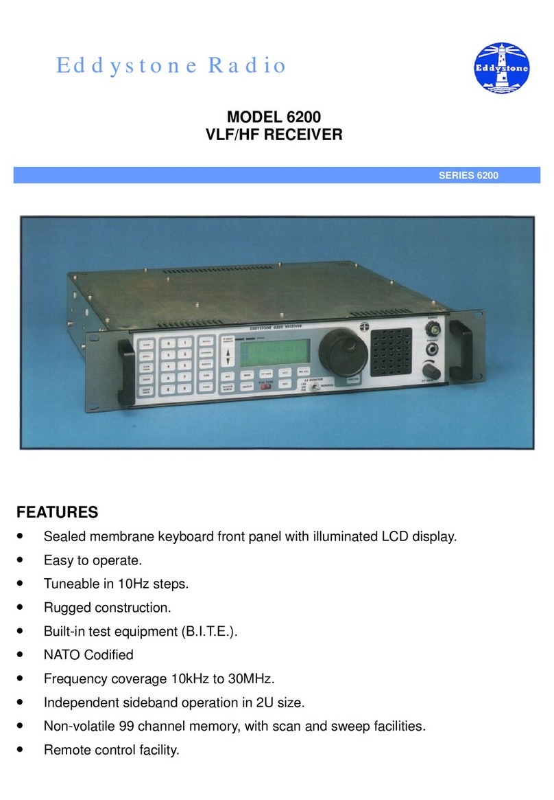
Eddystone 6200 Owner's manual

Eddystone
Eddystone 880 User manual
