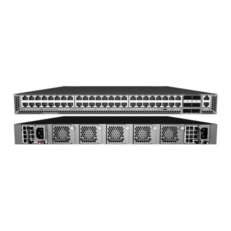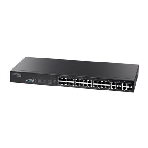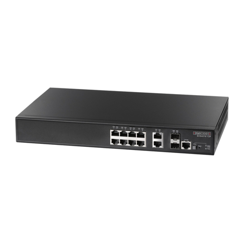
Quick Start Guide
– 2 –
1. Use the DC ring lugs included with the DC PSU.
2. Connect the DC return wire.
3. Connect the -36 – -72 VDC wire.
Verify Router Operation
1. Verify basic router operation by checking the system LEDs.
When operating normally, the PSU0/PSU1, Diag, and Fan LEDs
should all be on green.
Perform Initial System Boot
1. If the network operating system (NOS) installer is located on a
network server, first connect the RJ-45 Management (Mgmt) port
to the network using 100-ohm Category 5, 5e or better twisted-
pair cable. (Not required if the NOS installer is located on
attached storage.)
2. Boot the router. Wait for the ONIE software to locate and
execute the NOS installer, and then wait for the installer to load
the NOS software image.
Subsequent router boots will bypass ONIE and directly run the
NOS software.
Connect Network Cables
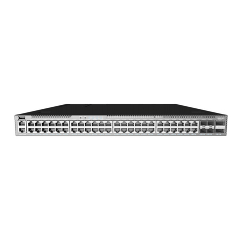
1. For the RJ-45 Management port, connect 100-ohm Category 5,
5e or better twisted-pair cable.
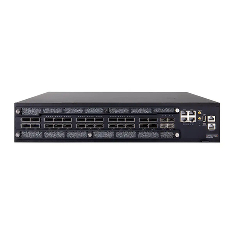
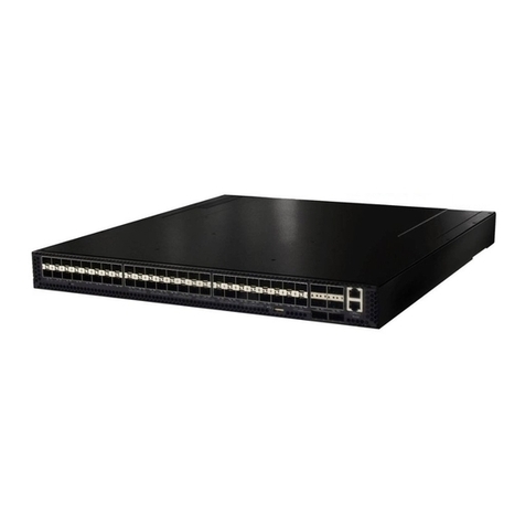
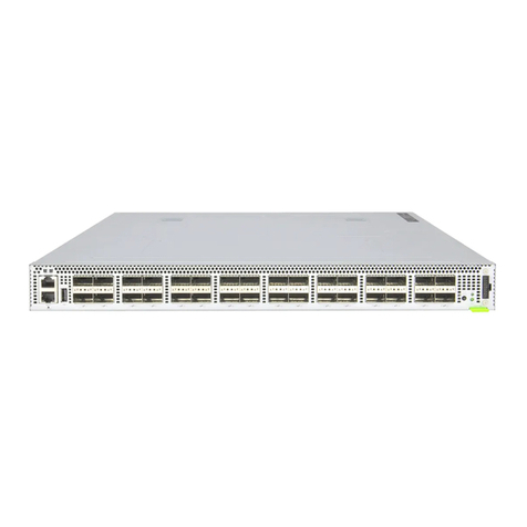
2. Connect DAC cables to the SFP28/QSFP28 slots. Or first install
SFP28/QSFP28 transceivers in the slots and then connect fiber
optic cabling to the transceiver ports.
3. As connections are made, check the port status LEDs to be sure
the links are valid.
For the SFP28 ports:
■Green — 25 Gbps mode
■Amber — 10 Gbps mode
Each QSFP28 port has four LEDs that indicate valid links in the
following modes:
■1 LED Green — 100 Gbps mode
■1 LED Blue — 40 Gbps mode
■1-4 LEDs Amber — 25 Gbps breakout mode (four lanes)
■1-4 LEDs Purple — 10 Gbps breakout mode (four lanes)
Connect Timing Ports and GPS Antenna
1. Use coax cables to connect the 1-pulse-per-second (1PPS) in/
out ports to other synchronized devices.
2. Use coax cables to connect the 10 MHz in/out ports to other
synchronized devices.
3. Attach an external GPS antenna to the GPS Antenna port for
clock synchronization with GPS time.
4. Use a shielded cable to connect the Time-of-Day (ToD) port to
other devices that use ToD synchronization signals.
5. Use a shielded cable to connect the Building-Integrated Timing
Supply (BITS) port to other devices that use BITS synchronization
signals.
Caution:
Use a UL/IEC/EN 60950-1 certified power
supply to connect to a DC converter, and a #14 AWG (for -
36 VDC to -72 VDC PSU) wire to connect to a DC PSU.
Attention:
Utilisez une alimentation certifiée UL/IEC/EN
60950-1 pour le connecter à un convertisseur CC et un
câble AWG #14 (pour -36 VDC à -72 VDC) pour vous
connecter à une alimentation CC.
Note:
Refer to the network operating system (NOS) installer
and NOS documentation for details on software options
and set up for ONIE.
