Edgetech 6205S2 User manual

ii
6205s2 BATHYMETRIC AND SIDE SCAN SONAR 0025262_REV_C
The information, figures, and specifications in this manual are proprietary. They are issued in strict
confidence on the condition that they not be copied, reprinted, or disclosed to a third party, either wholly
or in part, without the prior written consent of EdgeTech. Any reproduction of EdgeTech-supplied
software or file sharing is strictly prohibited.
EdgeTech © 2018 - 2023. All rights reserved.
Microsoft®, Windows®, and IoT® are registered trademarks of Microsoft Corporation.
Getac® is a registered trademark of MiTAC-Synnex Group.
HYPACK® and HYSWEEP® are registered trademarks of Hypack, Inc.
SonarWiz® is a registered trademark of Chesapeake Technologies Inc.
CARIS® is a registered trademark of Teledyne Caris.
EIVA NaviSuite® is a registered trademark of Eiva.
QINSY® is a registered trademark of QPS.
Applanix POSMV® is a registered trademark of Applanix.
Ekinox® and Apogee® are registered trademarks of SBG Corporation.
BEAMWORX® is a registered trademark of BeamworX B.V.
LMR® is a registered trademark of Times Microwave Systems.
Loctite®is a registered trademark of the Henkel Corporation.
SKB® is a registered trademark of the MEI Research Corporation.

iii
ATTENTION – READ THIS FIRST!
Warnings, Cautions, and Notes
Where applicable, warnings, cautions, and notes are provided in this manual as follows:
WARNING! Identifies a potential hazard that could cause injury or
death.
CAUTION! Identifies a potential hazard that could damage equipment or
data.
NOTE: Recommendations or general information that is particular to the
presented material.
All personnel involved with installing, operating, or maintaining the equipment described in this manual
should read and understand the warnings and cautions provided below.
CAUTION! This equipment contains devices that are extremely sensitive
to static electricity. Therefore, extreme care should be taken when
handling them. Normal handling precautions involve using anti-static
protection materials and grounding straps for personnel.
WARNING! High Voltage may be present in all parts of the system.
Therefore, use caution when the electronics are removed from their
containers for servicing.
CAUTION! Operation with improper line voltage may cause serious
damage to the equipment. Always ensure that the proper line voltage is
used.

iv
6205s2 BATHYMETRIC AND SIDE SCAN SONAR 0025262_REV_C
HARDWARE VARIATIONS AND COMPATIBILITY
The 6205s2 Bathymetry & Side Scan System contains both standard and proprietary hardware. At times,
EdgeTech may change the standard components due to their availability or performance improvements.
Although the component manufacturers and their models and styles—may change from unit to unit,
replacement parts will generally be interchangeable.
EdgeTech will make every effort to see that replacement components are interchangeable and use the
same software drivers (if applicable). At times, however, direct replacements may not exist. EdgeTech will
provide the necessary drivers with the replacement part when this happens.
EdgeTech may also change certain hardware per customer requirements. Therefore, portions of this
manual, such as parts lists and test features, are subject to change. These sections should be used for
reference only. When changes are made that affect system operation, they will be explicitly noted. Also,
some options and features may not be active in the customer's unit at the time of delivery. Upgrades will
be made available when these features are implemented.
Contact EDGETECH CUSTOMER SERVICE with any questions relating to compatibility.

v
ABOUT THIS DOCUMENT
We, the employees at EdgeTech, would like to thank you for purchasing a 6205s2 system. At EdgeTech,
our policy is to provide high-quality, cost-effective products and support services that meet or exceed
your requirements. We also strive to deliver them on time and continuously look for ways to improve
them. We take pride in the products we manufacture and want you to be entirely satisfied with your
equipment.
Purpose of this Manual
The purpose of this manual is to provide the user with information on the setup and use of EdgeTech's
6205s2 Bathymetry & Side Scan System. Although this manual encompasses the latest operational
features of the 6205s2, some features may be periodically upgraded. Therefore, the information in this
manual is subject to change and should be used for reference only.
Liability
EdgeTech has made every effort to document the 6205s2 Bathymetry & Side Scan System. However,
EdgeTech assumes no liability for errors or any damages resulting from the use of this manual or the
equipment it documents. EdgeTech reserves the right to upgrade this equipment's features and make
changes to this manual without notice at any time.
Revision History
REVISION
DESCRIPTION
DATE
APPROVAL
A
Release to Production
5/20/2022
B
OEM, Anode, Gap Fill Updates
8/18/2023
JF
C
Windows IoT Remote Desktop Update, Networking
Update
12/19/2023 JF

vi
6205s2 BATHYMETRIC AND SIDE SCAN SONAR 0025262_REV_C
WARRANTY STATEMENT
All equipment manufactured by EdgeTech is warranted against defective components and workmanship
for a period of one year after shipment. Warranty repair will be done by EdgeTech free of charge.
Shipping costs are to be borne by the customer. Malfunction due to improper use is not covered in the
warranty, and EdgeTech disclaims any liability for consequential damage resulting from defects in the
equipment's performance. No product is warranted as fit for a particular purpose, and there is no
merchantability warranty. This warranty applies only if:
i. The items are used solely under the operating conditions and in the manner recommended in the
seller's instruction manual, specifications, or other literature.
ii. The items have not been misused or abused in any manner, nor have repairs been attempted
thereon without the approval of EDGETECH CUSTOMER SERVICE.
iii. Written notice of the failure within the warranty period is forwarded to the seller, and the
directions received for properly identifying items returned under warranty are followed.
iv. The return notice authorizes the seller to examine and disassemble returned products to the
extent the Seller deems necessary to ascertain the cause for failure.
The warranties expressed herein are exclusive. There are no other warranties beyond those, either
expressed or implied herein. The seller does not assume any other obligation or liability in connection
with the sale or use of said products. Any product or service repaired under this warranty shall only be
warranted for the remaining portion of the original warranty period.
Equipment not manufactured by EdgeTech is supported only to the extent of the original manufacturer's
warranties.

vii
SOFTWARE SERVICE OVERVIEW
EdgeTech provides software services free of charge. This software agreement does not address customer-
specified modifications or enhancements. These services may be ordered separately. Furthermore,
EdgeTech software upgrades are meant for the sole use of EdgeTech customers. Any reproduction of
EdgeTech-supplied software or file sharing is strictly prohibited.
Software Updates and Enhancements
EdgeTech customers can download new software releases with all modifications and enhancements by
contacting EDGETECH CUSTOMER SERVICE. Should major software issues occur, they will be reported directly
to the customer. New software releases consist of the following:
•Software enhancements that are not on the price list
•Software fixes and changes
•Product integration
•Documentation updates to online help
•Tests for compatibility with other modules
Software patches consist of software that has undergone the following:
•Minor software enhancements
•Software fixes and changes
EdgeTech customers are entitled to contact EDGETECH CUSTOMER SERVICE by telephone, facsimile, or e-mail
to report a difficulty, discuss a problem, or receive advice on the best way to perform a task. When
contacted, EDGETECH CUSTOMER SERVICE will do the following:
•Respond within 24 hours via telephone, fax, and E-mail support
•Immediately attend to serious problems affecting operations
•Attempt to find an immediate workaround

viii
6205s2 BATHYMETRIC AND SIDE SCAN SONAR 0025262_REV_C
RETURNED MATERIAL AUTHORIZATION
Prior to returning any equipment to EdgeTech, a Returned Material Authorization (RMA) Number must
be obtained from CUSTOMER SERVICE.
RMA Purpose
The RMA number identifies returned equipment when it arrives at our receiving dock and enables tracking
while at our facility. Refer to the RMA number on all documentation and correspondences.
All returned materials must be shipped prepaid. Freight collect shipments will not be accepted. All
equipment should be adequately insured for shipping, but equipment belonging to EdgeTech must be
insured for full value.
If there is more than one item per consignment, include a packing with the shipment. An invoice can
double as a packing slip only when the contents are clearly numbered and identified on the invoice.
CAUTION! Never attempt to ship a topside unit in its SKB® case alone.
Although rugged, these cases are not intended to be used as shipping
containers, and the delicate internal components could be damaged.
Shipping in this manner will void any warranties.
NOTE: All shipping charges shall be the customer's responsibility unless
under warranty, as EdgeTech will pay for return shipping.
NOTE: For International Shipments valued over $1000, the following
Shipper's oath must be sent with the invoice.
Shipper's Oath:
"I, ______________________________, declare that the articles herein specified are the growth,
produce, or manufacture of the United States; that they were exported from the
United States from the port of _____________________, on or about _______________; that they
are returned without having been advanced in value or improved in condition by any
process of manufacture or any other means; and that no drawback, or allowance has
been paid or admitted hereof."
Signed ______________________________

ix
CUSTOMER SERVICE
Customer service personnel at EdgeTech are always eager to hear from users of our products. Your
feedback is welcome and is a valuable source of information that we use to improve these products.
Therefore, we encourage you to contact EdgeTech Customer Service to offer any suggestions or to request
technical support:
NOTE: Please have your system's serial number available when
contacting Customer Service.
E-mail: service@edgetech.com
Mail: 4 Little Brook Road
West Wareham, MA 02576
Telephone: (508) 291-0057
Fax:(508) 291-2491
24-Hour Emergency
Technical Support Line: (508) 942-8043
For more information, go to WWW.EDGETECH.COM.

x
6205s2 BATHYMETRIC AND SIDE SCAN SONAR 0025262_REV_C
COMPANY BACKGROUND
EdgeTech (formerly EG&G Marine Instruments) traces its history in underwater data acquisition and
processing back to 1966. EdgeTech has designed, developed, and manufactured products, instruments,
and systems for the acquisition of underwater data—including marine, estuarine, and coastal
applications—for over 50 years.
The company has responded to the scientific, naval, and offshore communities' needs by providing
equipment—such as sub-bottom profilers, side-scan sonar, acoustic releases, USBL positioning systems,
and bathymetric systems—that have become standards in the industry.
EdgeTech has also consistently anticipated and responded to future needs through an active research and
development program. Current efforts are focused on the application of cutting-edge CHIRP and acoustic
technology.

xi
TABLE OF CONTENTS
ATTENTION – READ THIS FIRST! .........................................................................................................iii
Warnings, Cautions, and Notes................................................................................................................ iii
HARDWARE VARIATIONS AND COMPATIBILITY..................................................................................iv
ABOUT THIS DOCUMENT....................................................................................................................v
Purpose of this Manual............................................................................................................................. v
Liability...................................................................................................................................................... v
Revision History ........................................................................................................................................ v
WARRANTY STATEMENT ...................................................................................................................vi
SOFTWARE SERVICE OVERVIEW........................................................................................................vii
Software Updates and Enhancements.................................................................................................... vii
RETURNED MATERIAL AUTHORIZATION ..........................................................................................viii
RMA Purpose ......................................................................................................................................... viii
CUSTOMER SERVICE..........................................................................................................................ix
COMPANY BACKGROUND ..................................................................................................................x
TABLE OF CONTENTS .........................................................................................................................xi
LIST OF FIGURES...............................................................................................................................xv
LIST OF TABLES ............................................................................................................................... xix
1.0 OVERVIEW..............................................................................................................................1-20
1.1 Applications ................................................................................................................................1-21
1.2 6205s2 Configuration Options ....................................................................................................1-21
1.2.1 Frequency Options.................................................................................................................1-21
1.2.2 OEM RTK GNSS Aided INS Unit ..............................................................................................1-21
1.2.3 Discover Software Bathymetric Gap-Fill Option ....................................................................1-22
1.3 Main System Components..........................................................................................................1-23
1.3.1 6205s2 Swath Bathymetry and Side Scan Sonar Head ..........................................................1-23
1.3.2 6205S2-R Rack Mounted Topside Sonar Interface Box .........................................................1-24
1.3.3 Discover Software ..................................................................................................................1-24
1.3.4 Third-Party Software..............................................................................................................1-25
1.3.5 Sonar Deck Cable ...................................................................................................................1-25
1.4 Optional Equipment....................................................................................................................1-26
1.4.1 Adaptor Flange Kit..................................................................................................................1-26

xii
6205s2 BATHYMETRIC AND SIDE SCAN SONAR 0025262_REV_C
1.4.2 EdgeTech Ruggedized Getac Laptop......................................................................................1-27
1.4.3 Integrated OEM RTK GNSS/INS Kit.........................................................................................1-27
1.4.4 GNSS/INS Unit Deck Cable .....................................................................................................1-28
1.4.5 GNSS/INS Antenna Cable .......................................................................................................1-28
2.0 SPECIFICATIONS......................................................................................................................2-29
2.1 Acoustic Specifications................................................................................................................2-29
2.2 Sonar Head Physical Specifications.............................................................................................2-30
2.3 Power Requirements ..................................................................................................................2-30
2.4 Environmental Specifications .....................................................................................................2-30
2.5 Topside Specifications.................................................................................................................2-31
2.6 Mechanical Drawings..................................................................................................................2-32
2.6.1 6205s2 Sonar Head Drawing..................................................................................................2-32
2.6.2 6205s2 Topside ......................................................................................................................2-38
3.0 TECHNICAL DESCRIPTION ........................................................................................................3-40
3.1 The 6205s2 Sonar Head ..............................................................................................................3-40
3.1.1 Sonar Arrays...........................................................................................................................3-41
3.1.2 Sonar Head Housing...............................................................................................................3-41
3.1.2.1 Sonar Processor...............................................................................................................3-41
3.1.2.2 Sonar Processor Endcap and Pinout Drawings................................................................3-42
3.1.2.3 Sound Velocity Sensor.....................................................................................................3-44
3.1.2.4 Anodes.............................................................................................................................3-45
3.1.3 Mounting Plate ......................................................................................................................3-45
3.1.4 Acoustic Center......................................................................................................................3-46
3.2 The 6205s2 Topside Sonar Interface Box....................................................................................3-49
3.2.1 6205s2-R Rack Mount Topside Interface Box........................................................................3-50
3.2.1.1 6205s2-R Topside Connectors, Switches, and Indicator Lights .......................................3-50
3.2.2 6205s2-S Stack Topside Interface ..........................................................................................3-52
3.2.3 Topside Computer Requirements Specifications...................................................................3-52
4.0 CONNECTIONS AND FORMATS ................................................................................................4-53
4.1 Data Formats...............................................................................................................................4-53
4.2 System Connections and Data Flow............................................................................................4-54
4.2.1 Ethernet LAN Connections.....................................................................................................4-55
4.2.2 Connecting The 6205s2 To Devices On Another Network.....................................................4-56

xiii
4.2.3 Serial Port Connections..........................................................................................................4-63
4.2.4 Hardware Connectivity ..........................................................................................................4-63
4.2.4.1 Serial Port Configuration Examples.................................................................................4-64
4.2.4.2 Ethernet Port Configuration Examples............................................................................4-65
4.2.4.3 Integrated GNSS/INS Port Configuration Example..........................................................4-66
4.2.4.4 One PPS Port Configuration.............................................................................................4-67
4.2.5 Sonar Data Flow .....................................................................................................................4-68
4.3 Topside Provided Isolation..........................................................................................................4-71
5.0 INSTALLATION ........................................................................................................................5-44
5.1 Unpacking and Inspecting...........................................................................................................5-44
5.2 Sonar Head Installation...............................................................................................................5-44
5.2.1 Pole Mounting........................................................................................................................5-44
5.2.1.1 Over-the-Bow Deployment .............................................................................................5-45
5.2.1.2 Over-the-Side Deployment..............................................................................................5-45
5.2.2 USV Deployment....................................................................................................................5-46
5.3 Positioning the Topside Interface Box ........................................................................................5-46
6.0 CONNECT TO SONAR...............................................................................................................6-47
6.1 Connecting to Sonar via Windows Remote Desktop to Diagnose Connection Issues................6-47
6.1.1 Connecting to the 6205s2 using Windows Remote Desktop On Your Computer .................6-48
6.1.2 Windows Partition Lock / Unlock For Sonar Head Processors With A Windows 10 IoT Operating
System..............................................................................................................................................6-50
6.1.2.1 Verifying System’s Current Partition Lock State..............................................................6-50
6.1.2.2 Locking and Unlocking the System..................................................................................6-50
6.1.2.3 Changing the System State from Locked to Unlocked ....................................................6-51
6.1.2.4 Changing the System State from Unlocked to Locked ....................................................6-51
6.2 Confirming Supporting Data is Present.......................................................................................6-52
7.0 MAINTENANCE .......................................................................................................................7-55
7.1 Anode Inspection and Replacement...........................................................................................7-55
8.0 TROUBLESHOOTING................................................................................................................8-58
8.1 Troubleshooting the SV Sensor...................................................................................................8-58
8.2 Configuring Auxiliary Sensors for Redundant Information.........................................................8-61
8.2.1 Two Different Sensors Supplying the Same Message............................................................8-61
8.2.2 Two Sensors Output Same Information with Different Messages ........................................8-63

xiv
6205s2 BATHYMETRIC AND SIDE SCAN SONAR 0025262_REV_C
8.3 Configuring COM Ports ...............................................................................................................8-65
8.3.1 One Sensor.............................................................................................................................8-65
8.3.2 Two Sensors ...........................................................................................................................8-70
8.3.3 Three Sensors.........................................................................................................................8-72
8.3.4 UDP Connections ...................................................................................................................8-75
8.3.5 Applanix POS-MV Configuration ............................................................................................8-76
8.3.6 SBG Ekinox/Apogee Configuration.........................................................................................8-79
8.3.7 OEM Integrated SBG Ekinox Configuration............................................................................8-82
8.3.7.1 Lever Arm and GNSS Antenna Position Configuration....................................................8-83
8.3.8 OEM Integrated Trimble AP+ (Applanix OEM) Configuration................................................8-85
8.3.8.1 Lever Arm and GNSS Antenna Position Configuration....................................................8-85
8.4 Computer System Restoration....................................................................................................8-90
9.0 KITS ........................................................................................................................................9-93
9.1 Spare Kits ....................................................................................................................................9-93
9.2 Tool Kit ........................................................................................................................................9-98
9.3 Adaptor Flange Installation Kit ...................................................................................................9-99
9.4 Sensor SBG IMU and GNSS Installation Kit ...............................................................................9-100
A.0 COMPATIBLE SOFTWARE .....................................................................................................9-102
A.1 Discover Bathymetric................................................................................................................9-102
A.2 Third-Party Software.................................................................................................................9-102
A.2.1 HYPACK ..........................................................................................................................9-102
A.2.2 SonarWiz........................................................................................................................9-102
A.2.3 Qinsy..............................................................................................................................9-103
A.2.4 CARIS..............................................................................................................................9-103
A.2.5 EIVA NaviSuite ...............................................................................................................9-103
A.2.6 BEAMWORX Suite..........................................................................................................9-103

xv
LIST OF FIGURES
Figure 1-1: 850 kHz Gap-Fill Example.......................................................................................................1-22
Figure 1-2: 6205s2- Forward-Port View of Sonar Head ...........................................................................1-23
Figure 1-3: 6205s2 Aft-Starboard View of Sonar Head............................................................................1-23
Figure 1-4: 6205s2 Topside Interface Box on Hardened SKB® Case ........................................................1-24
Figure 1-5: Discover Bathymetric Software .............................................................................................1-25
Figure 1-6: Sonar Deck Cable ...................................................................................................................1-25
Figure 1-7: Optional Adaptor Flange Plate ..............................................................................................1-26
Figure 1-8: 6205s2 with Optional Adaptor Flange Plate Installed ...........................................................1-26
Figure 1-9: GETAC Laptop Computer .......................................................................................................1-27
Figure 1-10: GNSS Antenna and Cabling ..................................................................................................1-27
Figure 1-11: Example 6205s2 System with OEM RTK GNSS/INS Kit ........................................................1-28
Figure 1-12: GNSS/INS Deck Cable...........................................................................................................1-28
Figure 1-13: GNSS/INS Antenna Cable.....................................................................................................1-28
Figure 2-1: 6205s2 Sonar Head ICD .........................................................................................................2-32
Figure 2-2: 6205s2 Sonar Head with Adaptor Flange ICD........................................................................2-33
Figure 2-3: 6205s2 Side Scan Transducer ................................................................................................2-34
Figure 2-4: 6205s2 Side Scan Transducer Details ....................................................................................2-35
Figure 2-5: 6205s2 Deck Cable Wiring Diagram....................................................................................... 2-36
Figure 2-6: 6205s2 GNSS/INS Deck Cable Wiring Diagram ......................................................................2-37
Figure 2-7: 6205s2 Rack-Mounted Topside .............................................................................................2-38
Figure 2-8: 6205s2 Rack Mount in Case...................................................................................................2-39
Figure 3-1: 6205s2 Sonar Head Port View ...............................................................................................3-40
Figure 3-2: 6205s2 Aft View..................................................................................................................... 3-40
Figure 3-3: 6205S2 Forward View............................................................................................................ 3-40
Figure 3-4: 6205s2 With Nosecone Removed- AML SVT OEM Probe Is Visible. Optional Adaptor Flange
Installed On Top Of 6205s2 Housing........................................................................................................3-40
Figure 3-5: 6205s2 Forward Endcap ........................................................................................................3-42
Figure 3-6: 6205s2 Aft End Cap................................................................................................................ 3-43
Figure 3-7: 6205s2 Pinout Drawing.......................................................................................................... 3-44
Figure 3-8: Sound Velocity Sensor ...........................................................................................................3-44
Figure 3-9: 6205s2 Forward Two Anodes ................................................................................................3-45
Figure 3-10: 6205s2 After Anode ............................................................................................................. 3-45
Figure 3-11: The Mounting Plate .............................................................................................................3-45

xvi
6205s2 BATHYMETRIC AND SIDE SCAN SONAR 0025262_REV_C
Figure 3-12: The Optional Adaptor Flange Installed onto the Mounting Plate ....................................... 3-46
Figure 3-13: Acoustic Center Location in X, Y, and Z and Bolt Pattern of Standard 6205s2.................... 3-47
Figure 3-14: Acoustic Center Location in X, Y, Z Dimensions and Bolt Pattern with Adaptor Flange......3-48
Figure 3-15: 6205s2-R Topside Interface .................................................................................................3-50
Figure 3-16: Rack Mount Topside, Front Panel........................................................................................3-50
Figure 3-17: Rack Mount Topside, Rear Panel.........................................................................................3-50
Figure 4-1: Windows UI Remote Desktop Location.................................................................................4-56
Figure 4-2: Sonar Exe is Active, and System Status Is Locked..................................................................4-57
Figure 4-3: System Status Is UNLOCKED ..................................................................................................4-57
Figure 4-4: Windows Run Dialog With ncap.cpl Command Entered .......................................................4-58
Figure 4-5: Network Connections Dialog ................................................................................................. 4-58
Figure 4-6: Network Connection Right-Click Drop-Down Dialog .............................................................4-59
Figure 4-7: Ethernet Connection Properties Window-Internet Protocol Version 4 (TPC/IPv4) Selected 4-59
Figure 4-8: Internet Protocol Version 4 (TCP/IPv4) Properties Windows- Click Advanced Button .........4-60
Figure 4-9: Advanced TCP/IP Dialog-TCP/IP Address Input Dialog After Add Button Pushed.................4-61
Figure 4-10: Advanced TCP/IP Settings Dialog.........................................................................................4-62
Figure 4-11: Serial Port Connections .......................................................................................................4-63
Figure 4-12: 6205s2 Rack Mount Topside Interface Connections ...........................................................4-64
Figure 4-13: 6205s2-R Rack Mount Topside Interface Connections........................................................4-66
Figure 4-14: 6205s2-R Rack Mount Topside Interface Connections........................................................4-67
Figure 4-15: 6205s2 System Is Optimized To Work With A Falling Edge 1PPS Signal..............................4-68
Figure 4-16: Sonar Data Flowchart ..........................................................................................................4-69
Figure 4-17: Chevron Pattern Noise in a Cropped Portion of Discover Bathymetric ..............................4-71
Figure 5-1: 6205s2 Deployment, Option 1 – Over-the-Bow ....................................................................5-45
Figure 5-2: 6205s2 Deployment, Option 2 – Over-the-Side ....................................................................5-45
Figure 5-3: 6205s2 USV Deployment (IM Solutions USV) ........................................................................5-46
Figure 6-1: Discover Bathymetric Diagnostic Window ............................................................................6-47
Figure 6-2: Launching Remote Desktop from Windows Application Menu ............................................6-48
Figure 6-3: Navigating To The Remote Desktop Connection By Entering “mstsc” Into The Windows Taskbar
Search Field..............................................................................................................................................6-48
Figure 6-4: Manual Remote Desktop Credentials for Customer-Supplied Computer .............................6-49
Figure 6-5: Sonar 192.9.0.101 Remote Desktop Connection Window....................................................6-49
Figure 6-6: System Status Dialog Box when the System is Currently Locked. .........................................6-50
Figure 6-7: System Status Dialog Box when the System is Currently Unlocked. .....................................6-50
Figure 6-8: System Locker Desktop Icon..................................................................................................6-50

xvii
Figure 6-9: System Locker Display when System is Locked. ....................................................................6-51
Figure 6-10: System Locker Display when System is Unlocked ...............................................................6-51
Figure 6-11: Sonar 192.9.0.101 Remote Desktop Connection Window..................................................6-52
Figure 6-12: Serial Port Information Window.......................................................................................... 6-53
Figure 6-13: Sensor Usage Percentage Check..........................................................................................6-54
Figure 7-1: Anode Replacement: Nose Cone Removal............................................................................7-56
Figure 7-2: Anode Replacement: Unthreading [2] Forward Anodes. ......................................................7-56
Figure 7-3 Anode Replacement: [2] Forward Anodes Coated and Replaced ..........................................7-56
Figure 7-4: Anode Replacement- Unthreading [1] Aft Anode .................................................................7-57
Figure 7-5: Anode Replacement- Assemble [1] Bolt, [1] Plastic Washer and Coat With Aqualube ........7-57
Figure 7-6: Anode Replacement: [1] Aft Anode Assembly Coated and Replaced ................................... 7-57
Figure 8-1: No Sound Velocity on Port 4.................................................................................................. 8-58
Figure 8-2: Sonar 192.9.0.101 Remote Desktop Connection Window....................................................8-58
Figure 8-3: Closing the Sonar.exe Application .........................................................................................8-59
Figure 8-4: Connecting to COM4 using TeraTerm ...................................................................................8-59
Figure 8-5: COM4 Port Settings ...............................................................................................................8-60
Figure 8-6: Scrolling SV Data in Sonar.exe ...............................................................................................8-61
Figure 8-7: Configuration Menu...............................................................................................................8-62
Figure 8-8: Auxiliary Sensors....................................................................................................................8-62
Figure 8-9: Sonar Control Tab ..................................................................................................................8-63
Figure 8-10: SonarSerial.ini ......................................................................................................................8-64
Figure 8-11: Sonar Remote Desktop Application, Main Screen...............................................................8-65
Figure 8-12: Finding the SonarSerial.ini File ............................................................................................8-66
Figure 8-13: SonarSerial.ini File ............................................................................................................... 8-66
Figure 8-14: Diagnostic Window, Reporting Ports Inactive Error............................................................8-67
Figure 8-15: Sonar.Exe Desktop Location ................................................................................................8-67
Figure 8-16: Checking Serial Port Information.........................................................................................8-68
Figure 8-17: Checking Sensor Status........................................................................................................8-68
Figure 8-18: Closing the System Status Window .....................................................................................8-69
Figure 8-19: SonarSerial.ini File ............................................................................................................... 8-70
Figure 8-20: Checking Sensors’ Usages....................................................................................................8-71
Figure 8-21: All Sensors Set...................................................................................................................... 8-72
Figure 8-22: Checking all COM Ports........................................................................................................ 8-74
Figure 8-23: UDP Configuration Example ................................................................................................8-75
Figure 8-24: Example Applanix POS-MV GNSS/INS Unit..........................................................................8-76

xviii
6205s2 BATHYMETRIC AND SIDE SCAN SONAR 0025262_REV_C
Figure 8-25: POSMV UDP Configuration..................................................................................................8-77
Figure 8-26: SonarConfig.ini Example......................................................................................................8-78
Figure 8-27: TimeSyncSource Keyword Adjustments ..............................................................................8-78
Figure 8-28: Example SBG Systems GNSS/INS unit ..................................................................................8-79
Figure 8-29: Ekinox/Apogee Sonar.ini file TimeSyncSource Keyword Adjustments................................8-80
Figure 8-30: Ekinox/Apogee SonarSerial.ini File Adjustment ..................................................................8-80
Figure 8-31: UDP broadcast settings example.........................................................................................8-81
Figure 8-32: Data packets required, set using the recommended SBG's "Hydro-Hypack” .....................8-81
Figure 8-33: 1PPS settings example, Falling Edge and 1msec duration................................................... 8-82
Figure 8-34: SBG Systems OEM GNSS and INS units................................................................................8-82
Figure 8-35: Sensor Lever Arms Primary Lever Arm Values .................................................................... 8-83
Figure 8-36: Aiding Setting GPS1 GNSS Lever Arm Values.......................................................................8-84
Figure 8-37: Trimble Applanix OEM GNSS and INS units ......................................................................... 8-85
Figure 8-38: Primary Antenna Type Configuration ..................................................................................8-86
Figure 8-39: Secondary Antenna Type Configuration..............................................................................8-86
Figure 8-40: INS Remote settings and ANT#1 and ANT#2 Antenna Separation Values ..........................8-87
Figure 8-41: INS Remote settings and the Reference to ANT#1 Distance Values ...................................8-88
Figure 8-42: INS Remote settings and the Reference to Sensor 1 distance values .................................8-88
Figure 8-43: Example RTK / RTX Correction Controls ..............................................................................8-89
Figure 8-44: 1PPS configuration...............................................................................................................8-89
Figure 8-45: Example Security Configuration settings.............................................................................8-90
Figure 8-46: Restoration Edit Image Selection ........................................................................................8-91
Figure 8-47: Restoration- Add Search Path Confirmation Buttons..........................................................8-91
Figure 8-48: Restoration Restore Button.................................................................................................8-92
Figure 8-49: Restoration-Confirm Overwrite Continue Button ...............................................................8-92
Figure 9-1: 6205s2 Adaptor Flange Installation.......................................................................................9-99

xix
LIST OF TABLES
Table 2-2: Acoustic Specifications............................................................................................................ 2-29
Table 2-1: Physical Specifications ............................................................................................................2-30
Table 2-3: Power Requirements ..............................................................................................................2-30
Table 2-4: Environmental Specifications..................................................................................................2-30
Table 2-5: 6205s2 Topside Interface Specifications.................................................................................2-31
Table 3-1: 6205s2-R Topside Connectors, Switches, and Indicator Lights...............................................3-51
Table 9-1: 6205s2 Topside and Sonar Head Spare Kits............................................................................9-93
Table 9-2: 6205s2 Topside Sparse Kit ......................................................................................................9-93
Table 9-3: 6205S2 540/1600 kHz Side Scan /540 kHz Bathy Spares Kit................................................... 9-94
Table 9-4: 6205S2 540/850 kHz Side Scan/540 kHz Bathy Spares Kit......................................................9-95
Table 9-5: 6205S2 540/850 kHz Side Scan /850 kHz Bathy Spares Kit.....................................................9-96
Table 9-6: 6205S2 850/1600 kHz Side Scan/850 kHz Bathy Spares Kit....................................................9-97
Table 9-7: 6205s2 Tool Kit........................................................................................................................ 9-98
Table 9-8: 6205S2 Adaptor Flange Installation Kit...................................................................................9-99
Table 9-9: Sensor SBG IMU and GNSS Installation Kit ...........................................................................9-100
Table 9-10: Sensor Applanix Surfmaster IMU & GNSS Kit .....................................................................9-101

1-20
6205s2 BATHYMETRIC AND SIDE SCAN SONAR 0025262_REV_C
1.0 OVERVIEW
The EdgeTech 6205s2 is a fully integrated swath bathymetry and dual-frequency side-scan sonar system
that uses multiple receive elements and one discrete transmit element to produce real-time high-
resolution, side-scan imagery and three-dimensional maps of the seafloor. The 6205s2 overcomes the
limitations of multibeam echo sounders (MBES) and interferometric systems in shallow water using
EdgeTech’s unique Multi-Phase Echo Sounder (MPES) Technology. This hybrid approach combines
beamforming and phase discrimination techniques to determine each sounding along the seafloor. With
the integration of EdgeTech’s Full Spectrum® CHIRP technology, the 6205s22 exceeds IHO SP-44, NOAA,
and USACE specifications for feature detection and bathymetric point data uncertainty.
EdgeTech’s MPES technology enables the 6205s2 to produce a wider and cleaner swath (over 200°) than
current technologies, resulting in superior coverage enabling faster and safer survey completion. In
addition, the 6205s2 concurrently rejects multipath effects, reverberation, and acoustic noise commonly
encountered in shallow water environments.
The 6205s2 provides simultaneous dual-frequency side scan sonar, operating at 520/850kHz,
850/1600kHz, or 520/1600 kHz. The bathymetry operates at either 520kHz or 850kHz.
Additionally, EdgeTech’s latest 2205 electronics and modular arrays are utilized in the 6205s2, resulting
in an extremely lightweight design required for shallow water applications and vessels of opportunity. The
2205 electronics and arrays are mounted onto a streamlined body deployed over the bow or side or
underneath a crewed or uncrewed survey vessel. Sonar data is transferred from the transceiver to the
processing unit onboard via an Ethernet network interface.
The 6205s2 system and its available integrations offer a powerful and versatile acquisition system suitable
for many different survey applications. It includes an integrated sound velocity sensor. It interfaces with
most third-party acquisition and processing software packages, standard DGPS/RTK GNSS systems,
heading, motion, sound velocity profilers, and INS.
The 6205s2 key features include:
•Next-generation MPES technology
•Unrivaled swath coverage in shallow water when compared to other single-head systems
•Swath sectors of up to 200°
•Co-registered dual-frequency side scan and single-frequency bathymetry
•Superior multipath rejection
•IHO SP-44 Special Order compliant
•Equidistant and equiangular soundings output options
•Comes with EdgeTech’s Discover Bathymetric sonar control software
•Motion tolerant side scan
•Optional integrated OEM RTKGNSS-aided INS unit
•Optional EdgeTech 3400-OTS-based sub-bottom profiler kit that integrates sub-bottom data with
6206s2 bathymetry and side scan data.
•Optional Discover Software Bathymetric Gap Fill feature.
Other manuals for 6205S2
1
Table of contents
Other Edgetech Sonar manuals
Edgetech
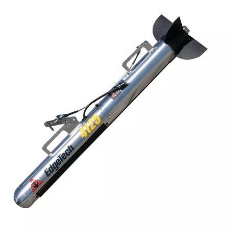
Edgetech 4125 Series User manual
Edgetech
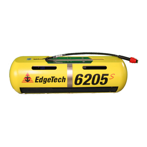
Edgetech 6205S User manual
Edgetech
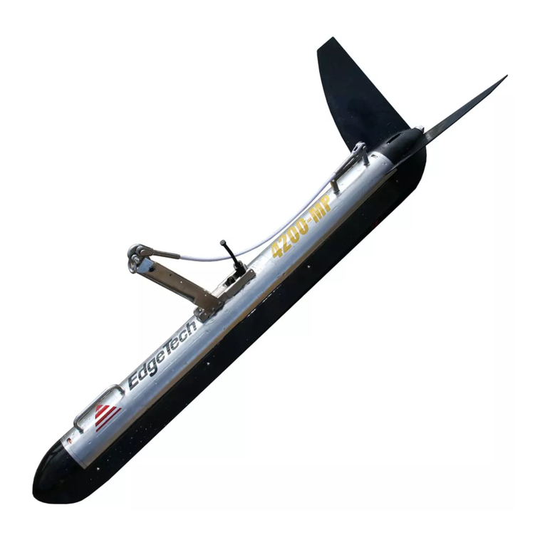
Edgetech 4200 User manual

Edgetech
Edgetech 2000-CSS User manual
Edgetech
Edgetech 2300 User manual

Edgetech
Edgetech 2300 User manual
Edgetech
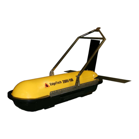
Edgetech 2000-TVD User manual
Edgetech
Edgetech 2205 Quick start guide
Edgetech
Edgetech 4125 SIDE SCAN User manual
Edgetech
Edgetech 3400 User manual

