Edgetech RH CAL User manual

RH CAL
Relative Humidity Calibrator
OPERATORS MANUAL
399 River Road ●Hudson, MA USA 01749
Tel. [508] 263-5900 ●[800] 276-3729 ●Fax [508] 486-9348
E-mail h2o@edgetechinstruments.com ●www.edgetechinstruments .com
Rev. A March 2011

2
TABLE OF CONTENTS Page
1.0 Quick Startup Card (Removable)
2.0 List of Illustrations 4
3.0 Introduction 5
3.1 General Description 5
3.2 System Overview 5
3.3 Operating Controls 6
4.0 Warranty Information 8
5.0 Edgetech Instruments Inc.’s Commitment to Quality 9
6.0 N.I.S.T. Traceability –What does It Mean? 10
7.0 Glossary 11
8.0 Installation 12
8.1 Unpacking 12
8.2 Wiring Connections 12
8.3 Water Fill 13
8.4 Air Connection (Optional) 13
9.0 Basic Block Diagram Theory of Operation 14
9.1 Basic Block Diagram Description 15
10.0 Panel Description 16
11.0 Information Display Functions 18
11.1 Information Displayed 18
12.0 Operating the RH Calibrator 20

3
12.1 System Status 20
12.2 Keypad Operation 21
12.3 Programming the RH-CAL 22
12.4 Calibrating RH Sensors 25
12.5 RS-232 Serial Port Setup 26
13.0 The Chilled Mirror Dew Point Sensor 30
13.1 Theory of Operation 30
13.2 Automatic Balance Cycle 31
13.3 Care and Maintenance of the Sensor 32
14.0 Maintenance 33
14.1 Routine Maintenance 33
14.1.1 Mirror Cleaning Schedule 33
14.1.2 Cleaning the Mirror 33
14.1.3 Dryer Tube Maintenance 34
14.1.4 Filling the Saturator 35
14.1.5 Removing the Front Panel 35
14.2 Replacing the Fuse 36
14.3 Modifying the Analog Output 36
15.0 Specifications 38

4
2.0 LIST OF ILLUSTRATIONS Page
3-1 RH Calibrator Panel 5
8-1 Removing Shipping Plug 12
8-2 Filling the Saturator 13
9-1 Basic Block Diagram 14
10-1 Panel Description 16
11-1 The Information Display 18
12-1 Keypad 21
12-2 Changing the RH Setpoint 22
12-3 Changing the AT Setpoint 22
12-4 Selecting Dew or Frost 24
12-5 Locking In the Changes 25
13-1 Chilled Mirror Block Diagram 30
14-1 Cleaning the Mirror 33
14-2 Replacing the Dryer Material 34
14-3 Fuse Location 36
14-4 Analog Mode Switch 36
14-5 DIP Switch Configuration 37

5
3.0 INTRODUCTION
3.1 GENERAL DESCRIPTION
The RH CALIBRATOR is a microprocessor based, programmable humidity control
and measurement instrument with many microprocessor controlled features built-in.
Using the NIST Traceable Optical Chilled Mirror primary measurement technique,
the RH CALIBRATOR was developed for precise calibration of RH Sensors and
Transmitters, as well as laboratory and research applications.
3.2 SYSTEM OVERVIEW
The RH CALIBRATOR has a Test Chamber, a menu driven LCD graphics display,
Automatic Balance Cycle (ABC), a selectable analog output, and an RS-232C serial
port.
Figure 3-1 RH Calibrator Panel

6
An Air Temperature Probe and a Type D2 Chilled Mirror Sensor are located in the
Test Chamber. The relative humidity and temperature of the chamber are
programmable from the Scrolling Menu.
The 40 x 8 character backlit LCD displays Dew Point (C or F), Chamber
Temperature (C or F), and Percent Relative Humidity simultaneously.
The Automatic Balance Cycle (ABC) can be set to balance the sensor optics at
preset times and intervals or can be initiated manually at any time.
An analog output is available on the Panel as either 0 to 5VDC or 4 to 20 ma, and it
can be set to follow any parameter with individually programmable high and low
points. The output can be set to Track the selected parameter value during the ABC
cycle or Hold the last value prior to the ABC cycle.
The half duplex configured RS-232C serial port can be used to remotely control the
calibrator operation, and to output data to a data recording device.
3.3 OPERATING CONTROLS
The RH CALIBRATOR operates entirely under microprocessor control. State-of-the-
art software provides the opportunity to include a flexible, informational, and user
friendly interface. The setup and operation of the control unit can be programmed via
the front panel keypad or the RS-232 serial port.
LCD Graphics Display: Displays three parameters simultaneously, time, date,
operational status, sensor mirror condition, and alerts the user to fault conditions.
When activated from the Scrolling Menu, the AT SETPOINT (chamber
temperature) and the RH SETPOINT (relative humidity), are displayed. The
display of Dew Point may also be selected with the Keyboard.
Keypad: A membrane type keypad allows the user to enter setup and instrument
control information. A Scrolling Menu guides the user through the setup
procedure. The Setup Parameters include RH SETPOINT, AT SETPOINT, time,
date, analog output parameter and scale, ABC start and interval, and serial port
settings.
SERVOLOCK ™: The SERVOLOCK feature continuously displays the servo
control loop status. This is especially useful when the sample dew point is
varying widely or quickly. When SERVOLOCK is displayed, the system is locked
on to and tracking the dew point.
ABC Cycle: The Automatic Balance Cycle checks for proper operation of the
system and re-balances the sensor to compensate for changes in reflectivity of
the mirror due to aging, optics drift, or minor contamination due to impurities in
the sample gas. The on board real time clock permits the user to program the

7
ABC cycle to start at any specified time of day and repeat at regular-
programmed intervals. The user can therefore program the ABC cycle to occur at
off-hours such as late at night or early morning when the re-balance will cause
the least interruption of the sampling process. The cycle can also be initiated
manually at any time by a pushbutton on the front panel or via the serial port.
The analog output can be programmed to either TRACK or HOLD the information
during an ABC cycle.
Serial Port: The RS-232C serial port can be used to remotely program setup
parameters, initiate an ABC cycle, or output data to a local or remote terminal,
printer, or computer. The data output function outputs, in ASCII format, the date,
time, three parameters, and system status to any RS232C equipped serial
device. The data can be sent on command from the external device or
automatically at programmed intervals. HELP and STATUS menus can also be
displayed to guide the user.
Analog Output: The analog output, either 0-5 VDC or 4-20 ma, is available at
the Panel terminal connector. The output can be set to track any parameter, and
may be independently scaled via the Scrolling Menu.

8
4.0 WARRANTY STATEMENT
All equipment manufactured by Edgetech Instruments Inc. is warranted against
defective components and workmanship for repair at their plant in
Massachusetts, free of charge, for a period of twelve months. Malfunction due
to improper use is not covered in this warranty and Edgetech Instruments Inc.
disclaims any liability for consequential damage resulting from defects in the
performance of the equipment. No product is warranted as being fit for a
particular purpose and there is no warranty of merchantability. This warranty
applies only if (i) the items are used solely under the operating conditions and
in the manner recommended in the instruction manual, specifications, or other
literature; (ii) the items have not been misused or abused in any manner or
repairs attempted thereon; (iii) written notice of the failure within the warranty
period is forwarded to Edgetech Instruments Inc. and the directions received for
properly identifying items returned under warranty are followed; and (iv) the
return notice authorizes Edgetech Instruments Inc. to examine and
disassemble returned products to the extent Edgetech Instruments Inc. deems
necessary to ascertain the cause for failure. The warranties expressed herein
are exclusive. There are no other warranties, either expressed or implied,
beyond those set forth herein, and Edgetech Instruments Inc. does not assume
any other obligation or liability in connection with the sale or use of said
products.
Equipment not manufactured by Edgetech Instruments Inc. is supported only to
the extent of the original manufacturer’s warranties

9
5.0 EDGETECH INSTRUMENTS INC.’S COMMITMENT
TO QUALITY
Thank you for purchasing one of our products. At Edgetech Instruments Inc.,
it is our policy to provide cost-effective products and support services that
meet or exceed you requirements, to deliver them on time, and to
continuously look for ways to improve both. We all take great pride in the
products we manufacture.
We want you to be entirely satisfied with your instrument. The information
contained in this manual will get you started. It tells you what you need to
get your equipment up and running, and introduces its many features.
We always enjoy hearing from the people who use our products. Your
experience with our products is an invaluable source of information that we
can use to continuously improve what we manufacture. We encourage you
to contact or visit us to discuss any issues whatsoever that relate to our
products or your application.
The Employees of Edgetech Instruments Inc.

10
6.0 N.I.S.T. TRACEABILITY –WHAT DOES IT MEAN?
The RH-CAL, or Relative Humidity Calibrator, is certified by Edgetech Instruments Inc.
to be traceable to N.I.S.T., the National Institute of Standards and Technology (formerly
known as the National Bureau of Standards, or NBS), in Gaithersburg, Maryland, U.S.A.
You have received a Certificate of Calibration with this instrument. What does N.I.S.T.
Traceability mean in terms of the RH-CAL?
The calibration chamber in the RH-CAL can be set by the user to any desired relative
humidity (RH). The instrument measures and controls the chamber RH by measuring
both the air temperature (AT) and the dew point temperature (DP) in the chamber.
Since there is a mathematical relationship between dew point temperature, air
temperature, and relative humidity, a built-in microprocessor can therefore compute the
chamber RH.
Dew Point is a fundamental measurement of humidity. It is not affected by temperature.
In addition, the chilled mirror dew point sensor in your RH-CAL provides a primary
rather then a secondary measurement of dew point temperature.
Both the AT and the DP are measured with Platinum Resistance Thermometers (PRTs).
These devices are coils of nearly pure platinum, where the rate of change of resistance
with temperature is precisely known. Resistance is accurately measured and is
automatically converted to temperature information in the RH-CAL.
TRACEABILITY:
1. The precise platinum thermometers are N.I.S.T. traceable by the traceable
resistance standards maintained by the PRT manufacturers.
2. A multi-point dew point calibration is performed on every RH-CAL chilled
mirror dew point sensor, using Edgetech Instruments Inc.’s traceable secondary
dew point standard. This instrument, a precise chilled mirror hygrometer, is
periodically sent directly to N.I.S.T. for certification against their dew point
transfer standard, a Two-Pressure Generator.

11
7.0 GLOSSARY
ABC: Automatic Balance Control –a method of maintaining accuracy in the
presence of contamination and minimizing maintenance requirements.
Analog Out A voltage or current that tracks changes in a parameter.
AT Air Temperature –the temperature inside the test chamber.
Depression The magnitude of available mirror cooling in the chilled mirror sensor.
Desiccant A chemical material which removes moisture from the air sample and
thereby produces very dry air.
DP Dew Point Temperature –the temperature that moisture in the
air just begins to condense on a cooled surface.
Hold Analog output which holds the last humidity reading just before the ABC
cycle.
Hysteresis The tendency of a sensor to give one set of readings when going up, and
a different set of reading when going down.
Mirror A small metallic reflective surface within the dew point sensor.
RH Percent Relative Humidity –the ratio between the actual moisture
content in the chamber and the maximum moisture content if the chamber
air was saturated, at a given air temperature.
RS-232 An accepted industry standard for a serial digital interface.
Saturator A device which brings the air sample to 100% RH.
Serial Port See RS-232.
ServolockTM A method of indicating that the system is locked on and tracking the dew
point.
Slew Rate The rate of temperature change of the mirror assembly in the chilled mirror
dew point sensor.
Track Analog output which follows (tracks) the mirror temperature during the
ABC cycle.
12
8.0 INSTALLATION
8.1 UNPACKING
Remove the RH CALIBRATOR from its shipping carton and remove any shipping
ties, clamps, and packing material. Save the Certificate of Calibration shipped
with this manual. Locate and save the Cleaner Kit included in the shipping
carton.
IMPORTANT:
1. Locate the RH-CAL on a flat horizontal surface. Leave a minimum of 6 inches
(15 cm) on both sides for proper air flow.
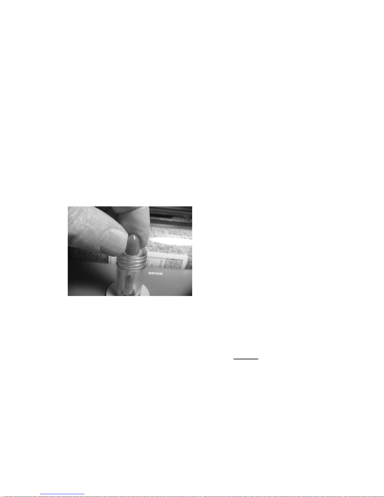
2. Before first use, unscrew the Saturator Cap and remove the Shipping Plug
(Red Top/Clear Tube) from the small stainless steel Saturator Air Outlet Tube.
Put the Shipping Plug away in a safe place –you may need it later.
Figure 8-1. Remove Shipping Plug NOTE: Whenever the RH CALIBRATOR
is moved, the saturator Shipping Plug
should be installed to prevent water
leakage.
8.2 WIRING CONNECTIONS
Connect the RH CALIBRATOR to a
grounded, instrument quality power
source of between 100 to 240 VAC, 50-60
Hz. There are no jumper or switch setting
modifications over this range; only the fuse must be changed if changing from a
nominal 115 VAC to 230 VAC.
Note: The correct fuse is installed at the Factory, depending upon the normally
supplied voltage at the shipping location.
Fuse Location: The AC power line fuse is located behind the left side of the
carrying handle, on a printed circuit board mounted inside the carrying case.
Fuse Values:
For U.S. use (and others): For power line voltage between 100 to 150 VAC, the
fuse type is 3A, 3AG, 250VAC, Slo-Blo. For power line voltage between 150 to
240 VAC, the fuse type is 1.5A, 3AG, 250 VAC, Slo-Blo.
For European use: Use Type T fuses. For nominal 230 VAC, the required fuse
value is 1.6A.
13
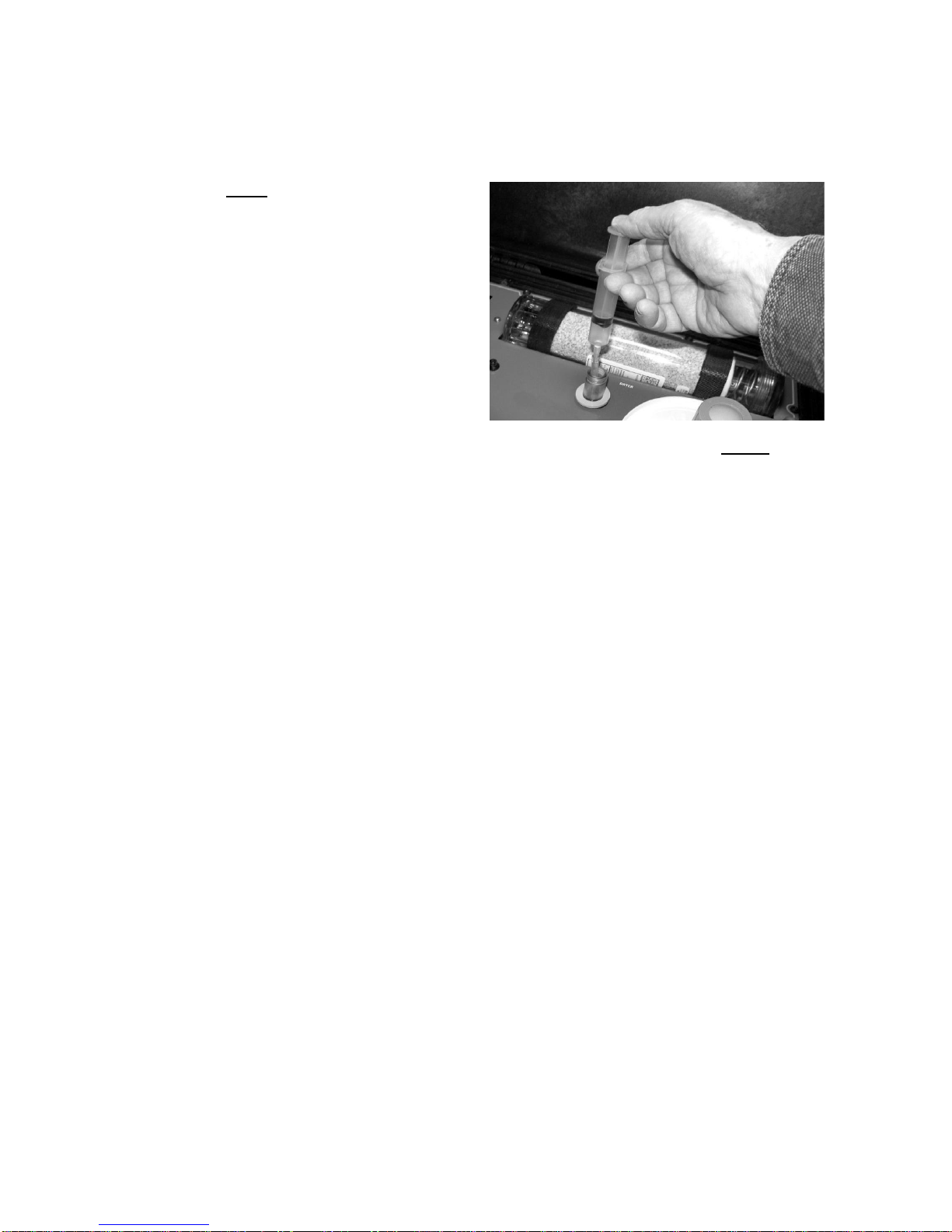
8.3 WATER FILL
Figure 8-2. Filling the Saturator
Note: Only distilled or deionized
water should be used. The
minerals in tap water may
gradually contaminate the
instrument and cause inaccurate
readings.
With power ON, remove the cap
from the clear water reservoir. Using
the supplied syringe, draw water into
the syringe until full. Place the
flexible hose at the end of the
syringe into the opened Saturator fill tube such that the tip extends below the
clear portion of the fill tube, and depress the plunger. Do not fill above the panel
surface. In case of overfill, draw the excess water into the syringe and bring the
water level below the clear portion of the fill tube. Total capacity of the Saturator
is approximately 40 ml (2 –3 full syringes). Replace the reservoir cap firmly.
8.4 AIR CONNECTION
(Optional)
A ¼ inch compression fitting is mounted on the panel. In normal portable
operation, it is not necessary to connect anything to this port, since room air is
automatically drawn into the calibrator, through the fitting, by the vacuum pump.
If you prefer to use your own source of instrument quality dry air, a ¼ inch line
may be connected. In this mode, the requirement for periodic maintenance of
the desiccant dryer material is eliminated.
Note: Air line pressure must NOT exceed 5 psig.
14
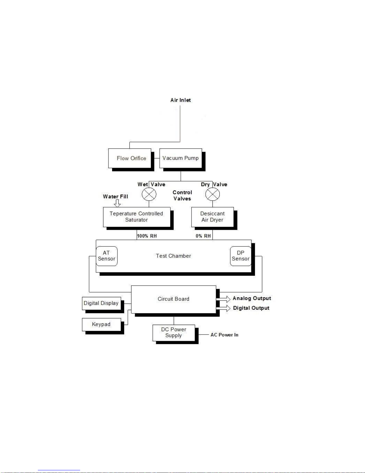
9.0 BASIC BLOCK DIAGRAM THEORY OF OPERATION
Figure 9-1. Basic Block Diagram

15
9.1 BASIC BLOCK DIAGRAM DESCRIPTION
See the Basic Block Diagram, Figure 9-1.
Room air enters the instrument, via the fitting on the panel. (Note: See the Installation
chapter regarding use of an instrument air line.)
A built-in Vacuum Pump is used to draw in the air sample, and to provide a positive
pressure in the Test Chamber.
The air flow is than divided and sent to a pair of finely matched volumetric Control
Valves. The RH CAL independently modulates the “Dry” and “Wet” valves from full-
open to full-closed, or any points between. The “Wet” valve feeds the heated
Saturator, which has a water fill mounted on the panel. The “Dry” valve feeds the Air
Dryer. When a desired RH setting is programmed into the instrument by the user, the
Control Valves automatically control the proper mixing of the wet and dry air in the
Test Chamber.
A Dew Point (DP) sensor is mounted within the Test Chamber. Control circuits on the
Circuit Board control the sensor mirror temperature, which tracks the Dew Point up
and down as it changes. An Air Temperature (AT) sensor is also installed in the Test
Chamber. Mounted in each of these sensors is a precise platinum thermometer to
provide AT and DP information. When the desired RH is selected by the user, a
microprocessor on the Circuit Board converts this information to Percent Relative
Humidity (RH). The proportion of wet and dry air in the chamber is automatically mixed
to keep it at the programmed RH at all times. In addition, the chamber Air
Temperature(AT) will also be controlled at any point programmed by the user.
An LCD Digital Display is mounted on the panel. It provides all pertinent information to
the operator, and allows programming of all parameters, including real time data. The
Keypad is used to enter desired programming information to the RH CAL.
The Analog Output (selectable 0 to 5 Vdc or 4 to 20 mA) is provided at a connector on
the panel. The Digital Output (RS-232C Serial Port) is also mounted on the panel.
A Power Supply module converts the AC power line voltage to DC to power the
electronic circuits.
16
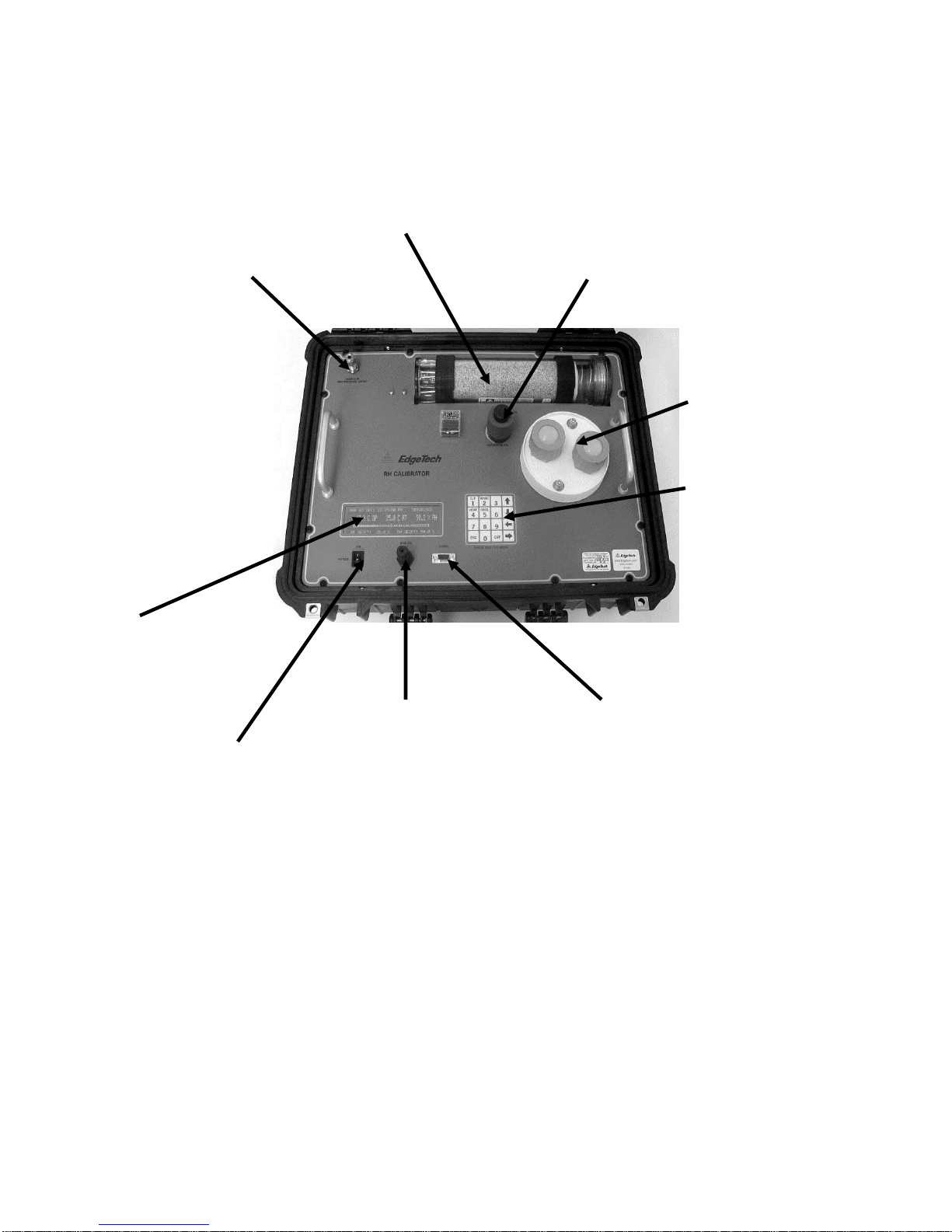
10.0 PANEL DESCRIPTION
2. AIR DRYER
1. AIR INLET 3. WATER FILL TUBE
4. TEST
CHAMBER
5. KEYPAD
9.
INFORMATION
DISPLAY
7. ANALOG OUTPUT 6. DIGITAL OUTPUT
8. ON/OFF SWITCH
Figure 10-1 RH-CAL Panel Description
1. Air Inlet (Sample In) –Brings in room air for use in the system. An
Instrument Air line may also be connected. (1/4 inch compression
fitting)
2. Air Dryer –Removes moisture from incoming air.
3. Water Fill Tube –Supplies water to the temperature controlled Saturator.

17
4. Test Chamber –Contains controlled RH and Temperature environment for
calibrating sensors.
5. Keypad –A pressure-sensitive keypad that allows the user to program setpoints
and to control functions.
6. Digital Output –RS-232C serial port for computer communication.
7. Analog Output –Can be programmed to provide information for Dew Point, Air
Temperature, or Percent Relative Humidity. User may select either 0 to 5 VDC
or 4 to 20 ma.
8. ON/OFF Switch –Turns Power ON or OFF.
9. Information Display –Reads out all system information, such as Set Points and
actual Test Chamber conditions.
ITEMS NOT SHOWN:
Air Outlet –on right rear of carrying case (1/4 inch compression fitting).
AC Power Input Socket and Fuse Holder –on left side of carrying case.

18
11.0 INFORMATION DISPLAY FUNCTIONS
Figure 11-1. The Information Display
11.1 INFORMATION DISPLAYED
The large LCD Display mounted on the Panel provides the user with all the information
necessary to properly operate the RH-CAL. It can be used as the primary interface with
the instrument, showing status of all parameters, and allowing calibration points to be
easily programmed.
NOTES:
1. The RS-232 Serial Port, along with a computer or terminal, may also
be remotely used for the same purpose.
2. All programming is in non-volatile memory, so that it is retained
when Power is off.
TOP ROW:
DATE The Current Date
TIME The Current Time
CONTROL LOOP STATUS Shows Chilled Mirror Control Loop
condition
CENTER ROW (MAIN DISPLAY):
DEW POINT The actual Chamber Dew Point
AIR TEMPERATURE The actual Chamber Temp.
RELATIVE HUMIDITY The actual %RH in the Chamber

19
Note: The above three parameters may be programmed to be
displayed in any desired sequence.
S_HEAT DISPLAY: Cycles on and off to show when
power is applied to Saturator
heater.
BAR GRAPH DISPLAY: The Bar Graph displays a picture of the
dew layer on the chilled mirror surface.
The right hand vertical bar indicates the
mirror itself, and the white bars show the
actual dew layer. The layer can be seen
to vary in thickness as the control loop
brings the mirror into control, and then
maintains a thin layer of dew as the
mirror temperature tracks the dew point
temperature.
BOTTOM ROW:
AIR TEMP. SETPOINT The programmable AT setting
RH SETPOINT The programmable RH setting

20
12.0 OPERATING THE RH CALIBRATOR
In order to operate this instrument, it is assumed that you have read the
INSTALLATION section of this manual, and preliminary tasks have been done.
These include:
1. The Shipping Plug has been removed from the Saturator Fill Tube.
2. The Saturator has been properly filled with water.
3. The instrument has been connected to the AC power source.
4. If desired, the Analog and/or Serial Digital (RS-232) Output has been wired.
If not, the INSTALLATION chapter should be reviewed before proceeding.
Turn the Power Switch to the ON position. The small adjacent indicator lamp will
light, and the Digital Display will: (1) light up; (2) briefly indicate RH
CALIBRATOR by EDGETECH INSTRUMENTS INC.; and (3) go into the normal
display mode. A hum will be heard, indicating that the fans and vacuum pump
are operating.
12.1 SYSTEM STATUS
The status of the RH-CAL control systems may be seen in the upper right corner
of the Display. When first turned on, it will read STARTUP. At other times, it
may read MAX HEAT, or ABC: HEAT, or ABC: STABLE, or SEEKING DP. After
several minutes, the Display will read SERVOLOCK. This indicates that the
system is tracking the Dew Point, and that the RH condition in the chamber is
stabilizing.
The chamber should only be used for calibration when the display reads
SERVOLOCK and the RH reading has stopped changing and reads the setpoint
value +/- the RH-CAL accuracy specification.
12.2 KEYPAD OPERATION
The RH CALIBRATOR Panel has six keys that support user set up and
operation. The label for each key, and its function, is described below.
Key Function
C/F Toggles the displayed parameters, internal parameters and RS-232 output
between degrees Fahrenheit and Centigrade. Output values are also converted
This manual suits for next models
1
Table of contents


