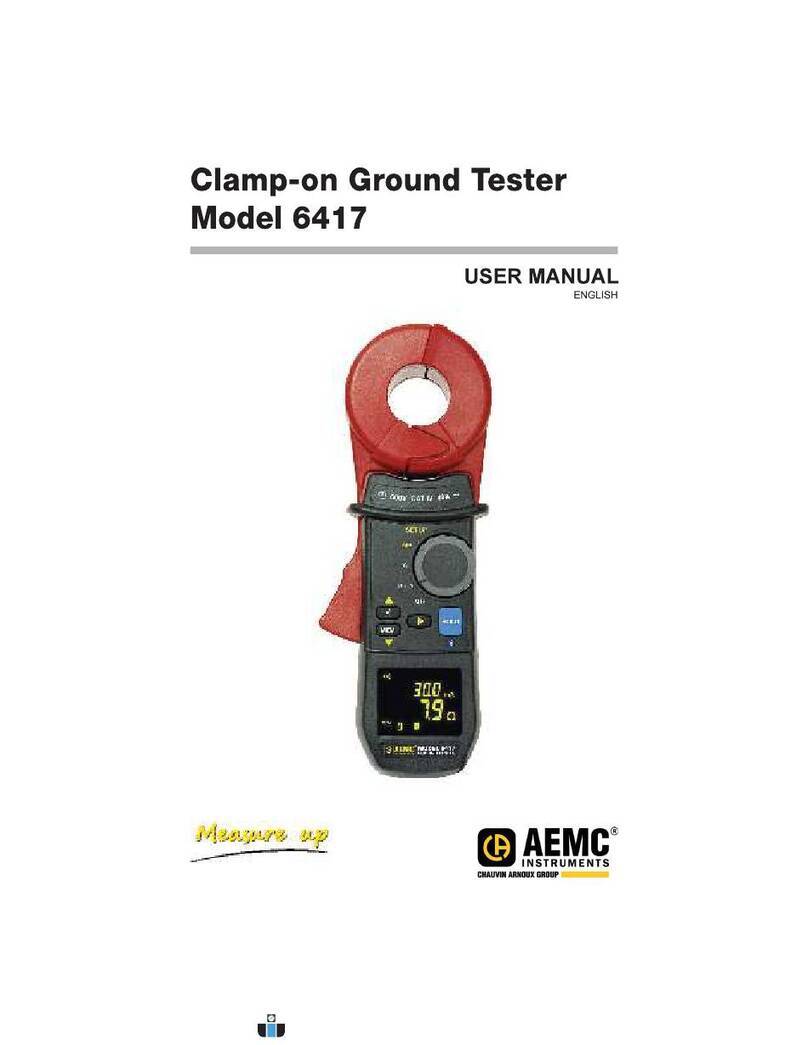
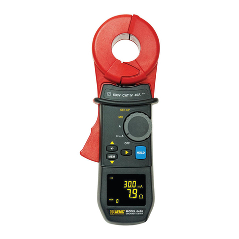
AEMC 6416 User manual

This document is confidential property of Chauvin Arnoux®, Inc. d.b.a. AEMC® Instruments and may not be reproduced without permission.
AEMC® Instruments retains the right to make changes to specifications herein at any time, without notice.
v1 – 11/23/15
SERVICE/CALIBRATION MANUAL
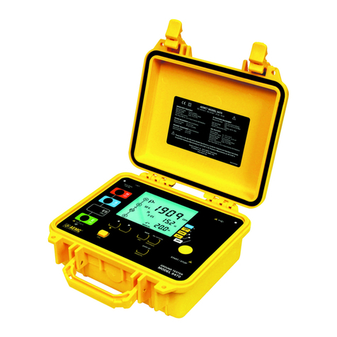
Clamp-On Ground Resistance Tester
AEMC®Model 6416/6417
(Chauvin Arnoux Model C.A 6416/C.A 6417)

MODEL 6416/6417 SERVICE/CALIBRATION MANUAL CAT# 2141.01/2141.02
v1 – 11/23/15 - 2 -
TABLE OF CONTENTS
REPAIR AND CALIBRATION ............................................................................ 3
SPECIFICATIONS ............................................................................................. 4
REFERENCE CONDITIONS .................................................................. 4
ELECTRICAL CHARACTERISTICS ....................................................... 4
LOOP RESISTANCE MEASUREMENT ...................................... 4
LOOP INDUCTANCE MEASUREMENT ...................................... 5
ESTIMATE OF THE CONTACT VOLTAGE ................................. 5
CURRENT MEASUREMENT ....................................................... 5
VARIATIONS IN THE DOMAIN OF USE ................................................ 6
POWER SUPPLY ................................................................................... 6
ENVIRONMENTAL CONDITIONS .......................................................... 7
MECHANICAL CHARACTERISTICS ...................................................... 7
COMPLIANCE WITH INTERNATIONAL STANDARDS ......................... 7
ELECTROMAGNETIC COMPATIBILITY ................................................ 7
MAINTENANCE ................................................................................................ 9
REPLACEMENT OF THE BATTERIES .................................................. 9
PROCEDURE .............................................................................. 9
PRESERVATION OF STORED DATA ......................................... 9
ACCURACY CHECK ......................................................................................... 10
EQUIPMENT ................................................................................ 10
PROCEDURE .............................................................................. 10
MANUAL CALIBRATION PROCEDURES ......................................................... 11
Revision Description Date Approved
1 Created Document 11/23/15 JPM

MODEL 6416/6417 SERVICE/CALIBRATION MANUAL CAT# 2141.01/2141.02
v1 – 11/23/15 - 3 -
REPAIR AND CALIBRATION
NOTE: Any attempts to repair and/or maintain this instrument, other than replacement of
fuses and batteries, voids the warranty of the instrument. The presence of high
voltages at certain locations requires servicing of this instrument by qualified
personnel. It is recommended that it be sent to an authorized service center.
To guarantee that your instrument complies with the factory specifications, we
recommend that the unit be submitted to our factory service center at one-year intervals
for recalibration, or as required by other standards.
For instrument repair and/or calibration, please call our factory at (800) 945-AEMC.
CHAUVIN ARNOUX, Inc.
d.b.a. AEMC® Instruments
15 Faraday Drive • Dover, NH 03820 USA
(800) 945-2362 • (603) 749-6434 • Fax: (603) 742-2346
(Or contact your authorized distributor.) Estimates for repairs, normal recalibration, and
calibration traceable to N.I.S.T. are available.
All customers must call for a return authorization number before returning any
instrument.
TECHNICAL AND SALES ASSISTANCE
If you are experiencing any technical problems, or require any assistance with the proper
use or application of this instrument, please call our technical hotline:
CHAUVIN ARNOUX, Inc.
d.b.a. AEMC® Instruments
(800) 343-1391 • (508) 698-2115 • Fax: (508) 698-2118
www.aemc.com

MODEL 6416/6417 SERVICE/CALIBRATION MANUAL CAT# 2141.01/2141.02
v1 – 11/23/15 - 4 -
SPECIFICATIONS
REFERENCE CONDITIONS
Quantities of influence Reference conditions
Ambient temperature 23±3°C.
Relative humidity 50%RH±10%
Battery voltage 6V±0.2V.
Magnetic field < 40A/m DC
No AC field
Electric field < 1V/m
Operating position Clamp horizontal
Position of the conductor in
the clamp
Centered
Measurement environment No adjacent conductors carrying current within 10cm
Proximity to magnetic mass > 10cm
Loop resistance Non-inductive resistance (20Ω for the voltage measurement)
Measured current, sinusoidal
frequency
Frequency 50Hz
Level of distortion < 0.5%
Spurious current in loop
resistance measurement
Zero for the resistance and inductance measurements.
< 3.75A for the voltage measurement,
ELECTRICAL CHARACTERISTICS
LOOP RESISTANCE MEASUREMENT
Measurement range:
- Loop ohmmeter function: 0.01 to 1500. 1500-counts display.
Measurement ranges (
) Resolution (
) Intrinsic uncertainty
0.010 to 0.099 0.001 ±1.5% ±0.01
0.10 to 0.99 0.01 ±1.5% ±2r
1.0 to 49.9 0.1 ±1.5% ±r
50.0 to 99.5 0.5 ±2% ±r
100 to 199 1 ±3% ±r
200 to 395 5 ±5% ±r
400 to 590 10 ±10% ±r
600 to 1,150 50 About 20%
1,200 to 1,500 50 About 25%
Alarm: range of threshold from 1
to 199
.
Measurement frequency: 2083Hz.
Transposition frequency: choice of 50, 60, 128, or 2083Hz for the impedance calculation.
Maximum overloads: - permanent current 100A maximum (50/60Hz).
- transient current (<5s) 200A (50/60Hz).

MODEL 6416/6417 SERVICE/CALIBRATION MANUAL CAT# 2141.01/2141.02
v1 – 11/23/15 - 5 -
LOOP INDUCTANCE MEASUREMENT
Measurement ranges (µH) Resolution (µH) Intrinsic uncertainty
10 to 100 1 ±5% ±r
100 to 500 1 ±3% ±r
ESTIMATE OF THE CONTACT VOLTAGE
Measurement range:
- Contact voltage function: value calculated as the product of the loop impedance by the
leakage current.
Measurement ranges (V) Resolution (V) Intrinsic uncertainty
0.1 to 4.9 0.1 ±5% ±r
5.0 to 49.5 0.5 ±5% ±r
50.0 to 75.0 1 ±10% ±r
Alarm: range of thresholds from 1V to 75V.
CURRENT MEASUREMENT
Measurement range:
- Ammeter function: 0.2 to 40A. 4000-counts display.
Measurement ranges (A) Resolution (A) Intrinsic uncertainty
0.200 to 0.999mA 1µA ±2% ±50µA
1.000 to 2.990mA
3.00 to 9.99mA
10µA ±2% ±50µA
10.00 to 29.90mA
30.0 to 99.9mA
100µA ±2% ± r
100.0 to 299.0mA
0.300 to 0.990 A
1mA ±2% ± r
1,000 to 2,990 A
3.00 to 39.99A
10mA ±2% ± r
Alarm: range of thresholds from 1mA to 40A.

MODEL 6416/6417 SERVICE/CALIBRATION MANUAL CAT# 2141.01/2141.02
v1 – 11/23/15 - 6 -
VARIATIONS IN THE DOMAIN OF USE
The influence is characterized by an Accuracy class number for each quantity of influence.
Quantity of
influence
Limit of the Domain
Quantities
influenced
Influence
Typical Max
Temperature -20°C to +55°C A, Ω
(1)
, Uc 1 P/10°C +r 2 P/10°C +r
Relative
humidity
10% RH to 90% RH A, Ω
(1)
, Uc P+r 3 P+r
Battery
voltage
4 to 6.5V A, Ω
(1)
, Uc 0.1 P+r 0.25 P+r
Position of
conductor
from the edge to the
center
A, Uc 0.1 P+r 0.2 P+r
Ω
(1)
0.05 P+r 0.1 P+r
Position of
clamp
+/-90°, 180° A 0.2 P+r 0.4 P+r
Uc, Ω
(1)
0.1 P+r 0.25 P+r
Proximity to
magnetic
mass
Steel sheet 1mm thick
against air gap
A, Ω
(1)
, Uc 0.1 P+r 0.5 P+r
Magnetic
field at 50 to
60Hz
30A/m A 2mA
(2)
4.5mA
(2)
Uc 0.1 P+r 0,5 P+r
Frequency of
the current
47 to 800Hz A, Uc P+r 2 P+r
Leakage
current at
50....60Hz
I<10A
RxI<50V
Ω
(1)
2 P+r 8 P+r
(1): Ω designates the quantities R, L, and Z.
(2): Offset on the current measurement.
POWER SUPPLY
■ 4x1.5V LR6 (AA) alkaline batteries or 4 NiMH batteries.
■ Mean consumption: approximately 140mA.
■ Mean life: approximately 12 hours, or 14,400 30-second measurements.
Remark: extreme environmental conditions may perturb the internal microprocessor. Simply
disconnecting the battery may be enough to eliminate this malfunction.
The batteries should be removed for long-term storage.

MODEL 6416/6417 SERVICE/CALIBRATION MANUAL CAT# 2141.01/2141.02
v1 – 11/23/15 - 7 -
ENVIRONMENTAL CONDITIONS
Fig. 1
1. Domain of reference (CEI160).
2. Domain of operation.
3. Domain of storage (without batteries). According to CEI359 category II
(equipment for indoor and outdoor use).
MECHANICAL CHARACTERISTICS
Dimensions: 55x95x262mm (thickness, width, height).
Max. clamping diameter: 35mm.
Weight: approximately 935g with batteries.
Display unit: 152-segment OLED. Active surface area 48x39mm.
Tightness: IP40, group III equipment.
Drop test: according to IEC-61010-1.
COMPLIANCE WITH INTERNATIONAL STANDARDS
Device fully protected by double insulation .
NF-EN-61010-2-032 Ed 2012, 600V, CAT IV.
ELECTROMAGNETIC COMPATIBILITY
The device is compliant with standard IEC-61326-1.

MODEL 6416/6417 SERVICE/CALIBRATION MANUAL CAT# 2141.01/2141.02
v1 – 11/23/15 - 8 -
6416/ 6417
Model 6416 Model 6417
Size
Weight
Max Conductor Size
Ohm Function 0.1 to 1500
Max Current for
Measurement 5A, 50V
Ampere Function 1mA to 40Arms
Display Hold Yes
Open Jaw Indicator Yes
Beeper Yes
Low Battery Indicator Yes
Alarm Function Yes, from 1 to 199
Memory Function 200 measurement 2000
Noise Detection Yes - indicator
Low Resistance Detection Yes - indicator < 1
Auto Power Off Yes, 5 minute delay
More Functions & Features
Model 6416 Model 6417
Auto-calibration Yes, runs calibration test of
all functions at power up
Auto-Off Yes, 5 min if not in use,
may be disabled by user
LCD Battery Life Indicator Yes, 0 to 100 % @ power up
LCD Noise Interference Indicator Yes
LCD Open Jaw Indicator Yes
LCD Closed Loop Indicator Yes
LCD Display Hold Yes, & A
Multi-tone Beeper Yes, may be disabled by user
Programmable Alarm Yes, from 1 to 199
high or low No
Programmable Memory Yes, up to 99 readings
( & A) No
Saved Programming @ Power
Off
Yes No
Construction GE Lexan® and IEC Standards
Safety Standards Built to IEC 1010, UL, CSA, CS

MODEL 6416/6417 SERVICE/CALIBRATION MANUAL CAT# 2141.01/2141.02
v1 – 11/23/15 - 9 -
MAINTENANCE
Disconnect everything connected to the device and set the switch to OFF.
Use a soft cloth, dampened with soapy water. Rinse with a damp cloth and dry rapidly
with a dry cloth or forced air. Do not use alcohol, solvents, or hydrocarbons.
Keep the air gap of the clamp perfectly clean.
REPLACEMENT OF THE BATTERIES
If the low battery symbol on the screen blinks, the batteries must be replaced promptly. Display
of the Lo bat message indicates that the batteries must be replaced for it to be possible once
again to use all functions of the clamp.
PROCEDURE
■ Disconnect everything connected to the device and set the switch to OFF.
■ Use a cross-headed or plain screwdriver to unscrew the 2 attachment screws and remove
the battery compartment cover.
■ Remove the old batteries and replace them with 4 new batteries having identical
characteristics (LR6, AA, 1.5V); observe the polarities.
Note: the alkaline batteries can be replaced by Cd-Ni or Ni-Mh rechargeable batteries (AA,
1.2V) having similar characteristics. However, the time between the low battery message
and the automatic switching off of the device will be shorter with the rechargeable batteries.
Spent batteries must not be treated as ordinary household waste.
Take them to the appropriate recycling collection point.
■ Close the battery compartment cover and screw the two screws back in.
■ Check the proper operation of the device.
PRESERVATION OF STORED DATA
When the batteries are removed, the data (recorded measurement values, alarm thresholds)
are preserved. The date and time must be reset if the batteries are out for more than 2
minutes.
MODEL 6416/6417 SERVICE/CALIBRATION MANUAL CAT# 2141.01/2141.02
v1 – 11/23/15 - 10 -
ACCURACY CHECK
AEMC recommends to calibrate the meters once a year and to check the probe with the supply
5Ω loop.
EQUIPMENT
1 high accuracy decade box: IET lab or equivalent,
1 lead with known resistance
1 AC current calibrator 50/60 Hz Fluke 5502 or equivalent
PROCEDURE
Place the lead in the jaws of the clamp and set the function switch of the device to Ω+A.
Connect the lead to the AC calibrator and supply the values from the table below.
Connect the lead to the decade box and set the dial to the table below. (be sure to include the
lead resistance)
FUNCTION
TESTED RANGE STANDARD
VALUE
TOLERANCE
MIN MAX
AC Current A 1.1 mA 1.028 mA 1.172 mA
60 Hz 110 mA 107.7 mA 113.2 mA
1.10 A 1.068 A 1.132 A
11.0 A 10.77 A 11.23 A
38.0 A 37.23 A 38.77 A
Ohms 1.0 0.98 1.11
10.0 9.75 10.3
40.0 39.3 40.7
80.0 78.0 82.0
100.0 97.5 104
150.0 145 155
500.0 440 560
1000.0 800 1200
open Overload
Before After
ALARM Good Y/N
MEMORY Good Y/N
ADVANCE MODE Good Y/N
BLUETOOTH Good Y/N
Bluetooth communication is available only with the Model 6417.
If some values are outside the MIN and Max values, follow the calibration procedure in
the next section.

MODEL 6416/6417 SERVICE/CALIBRATION MANUAL CAT# 2141.01/2141.02
v1 – 11/23/15 - 11 -
MANUAL CALIBRATION PROCEDURES
The calibration procedure will not delete the factory defaults and it is possible to reset it
anytime from the SET-UP position.
Notes:
Restoring Default Factory Calibrations will erase any previously performed user
resistance or current calibrations.
1.1 Setup and Activate Calibration Mode
1.1.1 Power on the ground tester and select “SET-UP” rotary switch position.
1.1.2 Select the “CAL.” menu by pressing the ▲ key one time.
1.1.3 Activate the “CAL.” menu by simultaneously pressing the ▲, ▼, and ► keys.
1.2 Restore Default Factory Calibration
1.2.1 Navigate to the “CAL. dFLt.” menu.
1.2.2 Press and hold the ► key until the “PrES. rt.” message appears and starts
blinking (press should last approximately 3 seconds).
1.2.3 Press the ► key. “End dFLt. PASS” will be displayed.
1.2.4 Press the ► key to return to the “CAL. dFLt.” menu.
1.3 User Resistance Calibration
1.3.1 Remove any conductors from the jaws of the ground clamp.
1.3.2 Navigate to the “CAL. R” menu.
1.3.3 Press and hold the ► key until the “PrES. rt.” and “no LOOP.” messages
appear and start alternately blinking (press should last approximately 3
seconds).
1.3.4 Press the ► key to start the open loop section of the calibration (“run CAL.R”
will be displayed for approximately 15 seconds).
1.3.5 When the “SEt 5.00Ω” message appears, insert a loop of known resistance
between 5 and 25Ω.

MODEL 6416/6417 SERVICE/CALIBRATION MANUAL CAT# 2141.01/2141.02
v1 – 11/23/15 - 12 -
1.3.6 Enter the resistance of the loop using the ▲ and ▼ keys and press the ► key
to start the next section of the calibration (“run CAL.R” will be displayed for
approximately 10 seconds).
1.3.7 “End CAL.R PASS” or “End CAL.R FAIL” will be displayed at the end of the
calibration. Press the ► key to save the new user calibration and return to the
“CAL.R” menu
1.3.8 Retry the calibration if failed.

MODEL 6416/6417 SERVICE/CALIBRATION MANUAL CAT# 2141.01/2141.02
v1 – 11/23/15 - 13 -
User Current Calibration
1.3.9 Engage the jaws of the ground clamp around the current carrying conductor.
1.3.10 Navigate to the “CAL. I” menu.
1.3.11 Press and hold the ► key until the “PrES. rt.” and “100.0 mA SEt” messages
appear and start alternately blinking (press should last approximately 3
seconds).
1.3.12 Run a known current between 50 and 150 mA (60 Hz) through the current
carrying conductor.
1.3.13 Enter the current value using the ▲ and ▼ keys and press the ► key to start
the low current section of the calibration (“run CAL.I” will be displayed for
approximately 10 seconds).
1.3.14 When the “PrES. rt.” and “10.00 A SEt” messages appear and start
alternately blinking, run a known current between 9 and 10.5 A (60 Hz)
through the current carrying conductor.
1.3.15 Enter the current value using the ▲ and ▼ keys and press the ► key to start
the high current section of the calibration (“run CAL.I” will be displayed for
approximately 10 seconds).
1.3.16 “End CAL.I PASS” or “End CAL.I FAIL” will be displayed at the end of the
calibration. Press the ► key to save the new user calibration and return to the
“CAL.R” menu.
1.3.17 Retry the calibration if failed.
Note: if an adjustment operation fails (FAIL message), check that there is nothing interfering
with the closing of the clamp, then repeat the operation. If the problem persists, the clamp
must be sent back for repair to the manufacturer.

MODEL 6416/6417 SERVICE/CALIBRATION MANUAL CAT# 2141.01/2141.02
v1 – 11/23/15 - 14 -

MODEL 6416/6417 SERVICE/CALIBRATION MANUAL CAT# 2141.01/2141.02
This document is confidential property of Chauvin Arnoux®, Inc. d.b.a. AEMC® Instruments and may not be reproduced without permission.
AEMC® Instruments retains the right to make changes to specifications herein at any time, without notice.
Chauvin Arnoux®. Inc. d.b.a. AEMC® Instruments
15 Faraday Drive • Dover, NH 03820 USA
Phone: (603) 749-6434 • (800) 945-2362 • Fax: (603) 742-2346

MODEL 6416/6417 SERVICE/CALIBRATION MANUAL CAT# 2141.01/2141.02
This document is confidential property of Chauvin Arnoux®, Inc. d.b.a. AEMC® Instruments and may not be reproduced without permission.
AEMC® Instruments retains the right to make changes to specifications herein at any time, without notice.
www.aemc.com
Other manuals for 6416
3
This manual suits for next models
1
Table of contents
Other AEMC Test Equipment manuals

AEMC
AEMC 400D-6 User manual

AEMC
AEMC 6471 User manual

AEMC
AEMC Simple Logger AmpFlex AL24-2500 User manual

AEMC
AEMC FlexProbe 24-3001 User manual

AEMC
AEMC 6416 Installation and operating instructions

AEMC
AEMC GROUNDFLEX 6474 User manual

AEMC
AEMC MN03 User manual

AEMC
AEMC SR601 User manual

AEMC
AEMC OX 5042 User manual

AEMC
AEMC GROUNDFLEX 6474 User manual