EDI CMU-24VDC-ITL Series User manual
THIS MANUAL CONTAINS TECHNICAL INFORMATION FOR THE CMU-24VDC-ITL
SERIES ITS CABINET MONITOR UNIT.
REVISION: OCTOBER 2008
pn 888-3912-002
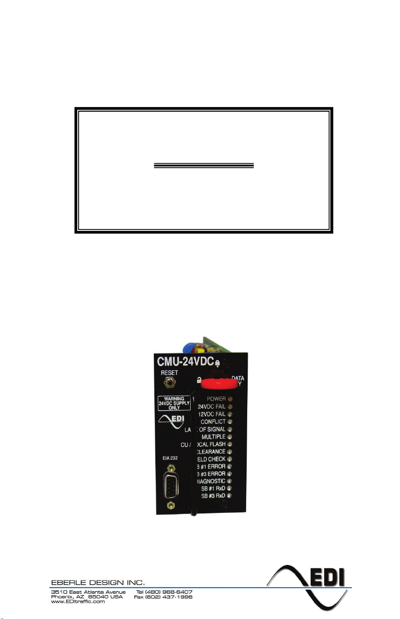
CMU-24VDC-ITL
Low Voltage DC Cabinet Monitor Unit
Operations Manual

THE CMU-24VDC SERIES CABINET MONITOR UNIT IS DESIGNED AND
MANUFACTURED IN THE USA BY
EBERLE DESIGN INC.
PHOENIX, ARIZONA.
AN ISO 9001:2015 REGISTERED COMPANY
INFORMATION CONTAINED HEREIN IS PROPRIETARY TECHNICAL INFORMATION
OF EBERLE DESIGN INC. PUBLICATION, REPRODUCTION OR USE IN WHOLE OR
PART IS NOT PERMITTED EXCEPT UNDER TERMS AGREED UPON IN WRITING.
©COPYRIGHT 2004-2008
U.S. Pat. No. 7,246,037
Canadian Patent No. 2,574,101
U.S. Pat. No. 9,460,620
MAINTENANCE NOTE
THIS EBERLE DESIGN INC. CABINET MONITOR UNIT HAS BEEN
CAREFULLY INSPECTED AND TESTED TO ENSURE PROPER
OPERATION. IT IS RECOMMENDED THAT THE CABINET MONITOR
UNIT BE TESTED AT LEAST ANNUALLY TO ENSURE PROPER
OPERATION AND COMPLIANCE WITH FACTORY SPECIFICATIONS.
- WARNING -
LED SIGNALS MUST MEET THE REQUIREMENTS
OF SECTION 3.2
CARE MUST BE TAKEN AT EACH INSTALLATION TO ENSURE
THAT THE TOTAL VOLTAGE DROP DUE TO SIGNAL LOAD
CURRENT IN BOTH THE FIELD WIRE AND FIELD RETURN WIRE
DOES NOT EXCEED 4 VOLTS TOTAL.

Table of Contents
Section 1 GENERAL ......................................................................................................... 1
1.1 Overview ................................................................................................................ 1
1.2 Channel Configuration............................................................................................ 1
1.3 Auxiliary Monitor Unit ............................................................................................. 1
1.4 CMU-24VDC Programming .................................................................................... 2
1.5 ECcom Software Interface...................................................................................... 2
1.6 Serial Bus #1.......................................................................................................... 2
1.6.1 Serial Bus #1 Message Types....................................................................... 3
1.7 Serial Bus #3.......................................................................................................... 3
1.7.1 Serial Bus #3 Message Types....................................................................... 3
1.8 Failed State Action (LFSA, LFSA-R, NFSA) ........................................................... 3
1.8.1 Exit From FSA............................................................................................... 3
Section 2 MONITOR FUNCTIONS .................................................................................... 4
2.1 Cabinet Power Supply Monitor ............................................................................... 4
2.2 Conflicting Channels Monitor.................................................................................. 4
2.3 Serial Bus Monitor.................................................................................................. 4
2.3.1 Serial Bus #1 Error........................................................................................ 4
2.3.2 Serial Bus #3 Error........................................................................................ 4
2.4 Type 62 FSA Message........................................................................................... 5
2.5 Lack of Signal Inputs Monitor ................................................................................. 5
2.6 Multiple Input Monitor ............................................................................................. 5
2.7 Yellow Clearance Monitor....................................................................................... 6
2.8 Yellow Plus Red Clearance Monitor ....................................................................... 6
2.9 Local Flash Status.................................................................................................. 6
2.9.1 Local Flash Status Recovery......................................................................... 6
2.10 Circuit Breaker Trip Status ................................................................................... 6
2.11 Flasher Unit Output Failed Alarm.......................................................................... 6
2.12 CMU Power Failure .............................................................................................. 7
2.12.1 24VDC Power Level Sense......................................................................... 7
2.12.2 Power Interrupt ........................................................................................... 7
2.12.3 Power Recovery.......................................................................................... 7
2.12.4 Power Up .................................................................................................... 7
2.12.5 Minimum Flash Interval ............................................................................... 7
2.13 Field Output Check............................................................................................... 7
2.13.1 Field Check Mode ....................................................................................... 8
2.13.2 Field Check Status ...................................................................................... 8
2.14 Diagnostic Error ................................................................................................... 8
2.14.1 Ram Memory Diagnostic............................................................................. 8
2.14.2 Nonvolatile Memory Diagnostic ................................................................... 9
2.14.3 Datakey Memory Diagnostic........................................................................ 9
2.14.4 Internal MPU Monitor .................................................................................. 9
2.15 Recurrent Pulse Detection.................................................................................... 9
2.15.1 Recurrent Pulse Detection Disable.............................................................10
Section 3 INPUT SIGNALS ..............................................................................................11
3.1 Field Signal Inputs (LEDguard)..............................................................................11
3.2 LED Signal Load Electrical Requirements .............................................................11
3.3 Load Switch Current..............................................................................................11
3.4 PDA Control Signal Inputs.....................................................................................12
3.4.1 Local Flash Status .......................................................................................12
3.4.2 Main Contactor (MC) Coil Status..................................................................12
3.4.3 Main Contactor (MC) Secondary Status .......................................................12
3.4.4 FTR Coil Drive Status ..................................................................................12

3.4.5 Circuit Breaker (CB) Trip Status ...................................................................12
3.4.6 Front / Rear Door Switch..............................................................................13
3.5 Monitor Interlock....................................................................................................13
3.6 External Test Reset input ......................................................................................13
3.7 Serial Bus #1 Address Inputs ................................................................................13
3.8 Serial Bus #1 Disable input ...................................................................................13
3.9 PDA Temperature .................................................................................................13
Section 4 FRONT PANEL DESCRIPTION .......................................................................14
4.1 Indicators ..............................................................................................................14
4.1.1 Power Indicator ............................................................................................14
4.1.2 24VDC FAIL Indicator ..................................................................................14
4.1.3 12VDC FAIL Indicator ..................................................................................14
4.1.4 CONFLICT Indicator ....................................................................................14
4.1.5 LACK OF SIGNAL Indicator .........................................................................14
4.1.6 MULTIPLE Indicator.....................................................................................14
4.1.7 CU / LOCAL FLASH Indicator ......................................................................14
4.1.8 CLEARANCE Indicator ................................................................................14
4.1.9 FIELD CHECK Indicator...............................................................................14
4.1.10 SB #1 ERROR Indicator.............................................................................14
4.1.11 SB #3 ERROR Indicator.............................................................................15
4.1.12 DIAGNOSTIC Indicator ..............................................................................15
4.1.13 SB #1 RX Indicator.....................................................................................15
4.1.14 SB #3 RX Indicator.....................................................................................15
4.2 Terminal Port.........................................................................................................15
4.3 Reset Button .........................................................................................................15
4.4 Datakey.................................................................................................................15
Section 5 SPECIFICATIONS............................................................................................16
5.1 Electrical ...............................................................................................................16
5.2 Timing ...................................................................................................................16
5.3 Mechanical............................................................................................................17
5.4 Environmental .......................................................................................................17
Section 6 CONNECTOR ASSIGNMENTS........................................................................18
6.1 Main DIN Connector..............................................................................................18
6.2 EIA-232 Connector................................................................................................18

CMU-24VDC-ITL Cabinet Monitor Unit
Operations Manual
Eberle Design Inc. Page 1
Section 1
GENERAL
1.1 OVERVIEW
The model CMU-24VDC Cabinet Monitor Unit (CMU-24VDC) is the principle part of the ITS
Traffic Control Cabinet Monitoring System. It is resident in the Power Distribution Assembly
and communicates with an Auxiliary Monitor Unit (AMU) located in each Output Assembly
via Serial Bus #3. The role of the CMU-24VDC is to query various cabinet conditions and, if
the application requires action, the CMU-24VDC will transfer control from the Advanced
Traffic Controller (ATC) to a flashing control mode. Applications include the detection of,
and response to, improper and conflicting signals and improper operating voltages in a
cabinet assembly caused by malfunctions of the (ATC), load switches, or miss wiring of the
cabinet.
The communications between the ATC and the CMU-24VDC via Serial Bus #1 plays an
integral role in ensuring safe and proper operation of the cabinet equipment as well as
providing important diagnostic functions used for trouble shooting malfunctioning
equipment.
The Eberle Design CMU-24VDC meets with or exceeds all appropriate specifications
outlined the ASHTO/ITE/NEMA Intelligent Transportation System (ITS) Standard
Specification for Roadside Cabinets Version 01.02.17b.
The Eberle Design CMU-24VDC is functionally interchangeable with a standard CMU-212
but is specially configured for low voltage (24Vdc) DC signal loads.
1.2 CHANNEL CONFIGURATION
The CMU-24VDC can be configured to monitor up to 28 physical load switch channels of
three inputs per channel. An additional four virtual channels can be programmed to provide
a total of 32 logical channels. Each channel is comprised of a Red / Don’t Walk input, a
Yellow input, and a Green / Walk input.
1.3 AUXILIARY MONITOR UNIT
The Auxiliary Monitor Unit (AMU-24VDC) provides the CMU-24VDC with voltage and
current measurements from each installed Output Assembly. The AMU-24VDC has the
capability to measure and report field terminal voltages for fourteen channels of three
inputs per channel and load currents for fourteen channels. The AMU-24VDC is also
compatible with a six position Output Assembly. The AMU is configured by its output
assembly address. This address is set by a jumper plug located on the rear of the output
assembly. For further information concerning the AMU-24VDC, see the Eberle Design
AMU-24VDC Operations Manual.
The AMU-24VDC address assignment specifies the physical arrangement of the Output
Assemblies. This defines the number of contiguous channels that the CMU-24VDC is
monitoring. An AMU-24VDC assigned as a 14 channel unit must be addressed as AMU #1
with AMU #2 reserved, or as AMU #3 with AMU #4 reserved. The following table shows the
ten possible cabinet configurations:
AMU #1
AMU #2
AMU #3
AMU #4
Monitored Channels
14
reserved
none
None
1 thru 14
14
reserved
14
reserved
1 thru 28
14
reserved
6
None
1 thru 20
14
reserved
6
6
1 thru 26
6
none
none
None
1 thru 6

CMU-24VDC-ITL Cabinet Monitor Unit
Operations Manual
Eberle Design Inc. Page 2
AMU #1
AMU #2
AMU #3
AMU #4
Monitored Channels
6
6
none
None
1 thru 12
6
6
6
None
1 thru 18
6
6
6
6
1 thru 24
6
none
14
reserved
1 thru 20
6
6
14
reserved
1 thru 26
The ATC must verify that all output assemblies being driven by a Serial Interface Unit
(SIU) are being monitored by an AMU-24VDC and that the AMU-24VDC is enabled by
the programming in the CMU-24VDC. Failure to provide this check may result in
unmonitored load switch outputs. This could occur as a result of improper configuration
of the cabinet, improper address assignment for one or more AMU-24VDC units, improper
address assignment for one or more SIU units, or improper programming of the ATC.
1.4 CMU-24VDC PROGRAMMING
The CMU-24VDC is individually configured using a removable nonvolatile memory device
called a Datakeytm (Datakey is a registered trademark of Datakey Electronics, Inc.). The
Datakey replaces the mechanical jumper or diode based program card used in
conventional signal monitors and provides an electronic method of programming the CMU-
24VDC. The Datakey contains a nonvolatile prom device that is read by the CMU-24VDC.
The Datakey itself is programmed by a separate programming device using a Personal
Computer program such as the Eberle Design MonitorKey product. See the Eberle Design
MonitorKey Operations Manual for further details.
The Datakey is interoperable with any CMU-24VDC meeting the requirements of the
ASHTO/ITE/NEMA Intelligent Transportation System (ITS) Standard Specification for
Roadside Cabinets Version 01.02.17b.
1.5 ECCOM SOFTWARE INTERFACE
The front panel display of the CMU-24VDC provides limited operational status. This status
includes real time indicators for Power, Serial Bus #1 activity, Serial Bus #3 activity, and
eleven latched indicators for fault conditions. Detailed status is obtained through the front
panel port using Eberle Design ECcom software running on a personal computer. The
ECcom software provides access to real time monitor data such as current field signal
status, field terminal voltages, cabinet control voltages, channel load current status,
temperature, and fault status. Historical event logs and signal sequence logs are also
provided. See the Eberle Design ECcom Operations Manual for further details.
1.6 SERIAL BUS #1
Serial Bus #1 provides a communication path between the CMU-24VDC to the ATC. The
communications between the ATC and the CMU-24VDC plays an integral role in ensuring
safe and proper operation of the cabinet equipment as well as providing important
diagnostic functions used for trouble shooting malfunctioning equipment. Standardized
communications can be broken into three categories; real time and latched fault status,
configuration verification, and malfunction detection and diagnosis.
Messages are defined that allow the ATC and the CMU-24VDC to perform redundant
checks on each other. The ATC has access to all CMU-24VDC information including field
signal input status, permissive programming, and fault status. This gives the ATC the
capability to provide a backup monitoring function and make enhanced event logging,
remote intersection monitoring, and remote diagnostics feasible. Similarly, the CMU-24VDC
receives information from the ATC that corresponds to the output commands to the load
switches. This data allows the CMU-24VDC to better respond to and diagnose fault
situations.

CMU-24VDC-ITL Cabinet Monitor Unit
Operations Manual
Eberle Design Inc. Page 3
1.6.1 SERIAL BUS #1 MESSAGE TYPES
The CMU-24VDC is compatible with the following message types:
Type 60 Module Identification Command / Type 188 Module Identification Response
Type 61 Load Switch Drivers Command / Type 189 CMU Status Response
Type 62 Set FSA Command / Type 190 FSA Response
Type 65 Get CMU Configuration Command / Type 193 CMU Configuration Response
Type 66 Time and Date Broadcast Command
Type 67 Load Switch Drivers Command / Type 195 CMU Short Status Response
1.7 SERIAL BUS #3
Serial Bus #3 is used to transfer data from a maximum of four AMU-24VDC units to the
CMU-24VDC. The CMU-24VDC then maps the retrieved data to the proper logical channel
and evaluates the state of the field signals for fault conditions. The CMU-24VDC is
compatible with AMU-24VDC units configured for 6-channel operation or 14-channel
operation.
1.7.1 SERIAL BUS #3 MESSAGE TYPES
The CMU-24VDC is compatible with the following message types:
Type 1 AMU 6 Status Command / Type 129 AMU 6 Status Response
Type 2 AMU 14 Status Command / Type 130 AMU 14 Status Response
Type 128 Negative Acknowledge Response
1.8 FAILED STATE ACTION (LFSA, LFSA-R, NFSA)
When triggered by the detection of a fault condition that exists longer than the minimum
defined period, the CMU-24VDC will enter the Failed State Action (fault) mode causing the
OUTPUT relay to de-energize and the contacts on the OUTPUT NO pins to open. The
cabinet assembly should be wired such that the opening of the OUTPUT NO relay contacts
will cause an automatic switching of the field signal outputs from normal operation to
flashing operation.
Only Unit Reset from the Reset Button or EXTERNAL RESET TEST input will reset the
CMU-24VDC from a LATCHED FAILED STATE ACTION (LFSA). Only a Unit Reset from
the Reset Button or EXTERNAL RESET TEST input or a CMU-24VDC Power Fail will reset
a LATCHED RESETTABLE FAILED STATE ACTION (LFSA-R).
A NONLATCHED FAILED STATE ACTION (NFSA) will be reset if the fault conditions
causing the NFSA have been removed. An NFSA will last for the programmed Minimum
Flash time at a minimum.
Only one LFSA, LFSA-R or NFSA fault state will be set at any time.
1.8.1 EXIT FROM FSA
Prior to the CMU-24VDC transferring the OUTPUT NO contacts from the FSA state to the
No Fault state, a transition period of 500 milliseconds will occur. During the transition period
the OUTPUT NO contacts will be in the FSA state and the CMU-24VDC will set the Start-
Up Flash Call bit in the Type 189 Frame to 1.At all other times the Start-Up Flash Call bit of
the Type 189 Frame will be set to 0. This provides an early indication to the ATC that exit
from the FSA state is occurring and the start-up phases should be set.

CMU-24VDC-ITL Cabinet Monitor Unit
Operations Manual
Eberle Design Inc. Page 4
Section 2
MONITOR FUNCTIONS
2.1 CABINET POWER SUPPLY MONITOR
The CMU-24VDC will sense the Cabinet +24VDC MONITOR and +12VDC MONITOR
power supply sources. The CMU-24VDC will also sense the Cabinet +24VDC MONITOR
state in each Output Assembly as reported by each AMU. Voltages equal to or greater than
+22 Vdc and +11 Vdc respectively will not cause a LFSA. Voltages at or less than +18 Vdc
and +9 Vdc for 500ms or longer will cause a LFSA. If the sensed voltage is less than +22
Vdc or +11 VDC for 200 ms or less, the CMU-24VDC will not cause a LFSA. All other
timing or voltage conditions may or may not cause LFSA. A +24VDC failure or +12VDC
failure during the programmed Minimum Flash time or during a CMU-24VDC Power Failure
will not cause a LFSA. The CMU-24VDC will report the value of the +24 VDC MONITOR
and +12 VDC power MONITOR supply sources in the Type 189 response frame.
There is programming in the Datakey to disable +12 VDC power supply monitoring.
NOTE: The Cabinet PDA +24VDC MONITOR function is disabled in the CMU-24VDC-
ITL firmware. The AMU 24VDC monitoring function is still active.
2.2 CONFLICTING CHANNELS MONITOR
For purpose of conflict determination, an active signal on either of the Green/Walk or
Yellow inputs associated with any of the 32 channels will be considered as that channel
being active. The Datakey will contain the permissive channel pair programming.
When any conflicting channels are detected as concurrently active for less than 200
milliseconds the CMU-24VDC will not cause a LFSA. When any conflicting channels are
detected as concurrently active for 500 milliseconds or more, the CMU-24VDC will cause a
LFSA. When any conflicting channels are detected as concurrently active for more than
200 milliseconds but less than 500 milliseconds, the CMU-24VDC may or may not cause a
LFSA.
2.3 SERIAL BUS MONITOR
The CMU-24VDC communicates with both Serial Bus (SB) #1 and #3. In SB #1 the CMU-
24VDC is a Secondary device, polled by the ATC Primary device. On SB #1, the CMU-
24VDC will respond to the Serial Bus #1 Address defined by the ADDRESS 0 and
ADDRESS 1 pins. On SB #3 the CMU-24VDC is the Primary device, polling each AMU-
24VDC Secondary device.
2.3.1 SERIAL BUS #1 ERROR
The CMU-24VDC will cause a FSA when a Type 61 or Type 67 Frame has not been
received from the ATC for greater than 1000 milliseconds. The first and second failures in a
24-hour period will be a NFSA. The third failure in a 24-hour period will be a LFSA-R. If a
CMU-24VDC Power Fail resets the LFSA-R, the SB #1 failure count will be reset to two,
such that the next SB #1 timeout results in a LFSA-R.
A SB #1 timeout failure during the programmed Minimum Flash time or during a CMU-
24VDC Power Failure will not cause a FSA. The SB #1 Timeout function will be disabled if
the SB #1 DISABLE input is at a True (Low) state
2.3.2 SERIAL BUS #3 ERROR
The CMU-24VDC will cause a FSA when a Type 129 or Type 130 Frame has not been
received from each AMU for greater than 300 milliseconds. The first and second failures in
a 24-hour period will be a NFSA. The third failure in a 24-hour period will be a LFSA-R. If a

CMU-24VDC-ITL Cabinet Monitor Unit
Operations Manual
Eberle Design Inc. Page 5
CMU-24VDC Power Fail resets the LFSA-R, the SB #3 timeout count will be reset to two,
such that the next SB #3 timeout results in a LFSA-R.
A SB #3 timeout failure during the programmed Minimum Flash time or during a CMU-
24VDC Power Failure will not cause a FSA.
2.4 TYPE 62 FSA MESSAGE
If the “N” bit is set in a Type 62 message, the CMU-24VDC will react by causing a NFSA.
The NFSA will remain until the receipt of a Message 62 with the “N” bit cleared or until the
CMU-24VDC is reset by a Unit Reset or CMU-24VDC Power Fail. The NFSA will last for
the programmed Minimum Flash time at a minimum.
If the “L” bit is set in a Type 62 message, the CMU-24VDC will react by causing a LFSA.
2.5 LACK OF SIGNAL INPUTS MONITOR
The CMU-24VDC will detect the absence of a required signal voltage on all the inputs of a
channel OR the absence of any required channel load current. For voltage purposes a
required signal on the Green OR Yellow OR Red inputs associated with a channel will be
considered as that channel being Voltage Active. For load current purposes a total channel
load current above the programmed threshold for a channel will be considered as that
channel being Current Active. When a channel is not Voltage Active OR Current Active for
less than 700 milliseconds, the CMU-24VDC will not cause a LFSA. When a channel is not
Voltage Active OR Current Active for greater than 1000 milliseconds, the CMU-24VDC will
cause a LFSA. When a channel is not Voltage Active OR Current Active for more than 700
milliseconds but less than 1000 milliseconds, the CMU-24VDC may or may not cause a
LFSA.
The Current Sense Unit (CSU) monitor function is hardwired to the maximum of 28 physical
channels, thus Virtual Channels do not have CSU monitoring capability. The CSU monitor
function must be disabled for any physical channel that has an input remapped to a Virtual
Channel.
Lack of Signal Input monitoring will be disabled for all channels when the MC COIL
STATUS input is not active. There is programming in the Datakey to disable Lack of Signal
Input monitoring on a per channel basis.
Lack of Signal Input monitoring will also be disabled for any channel which has the DARK
CHANNEL MAP bit set to "1" in the Datakey programming for the DARK CHANNEL MAP
addressed by the DARK CHANNEL MAP SELECT bits in a Type 61 message.
2.6 MULTIPLE INPUT MONITOR
The CMU-24VDC will detect the presence of an active signal on two or more inputs of a
channel. When the presence of an active signal on two or more inputs of a channel is
detected for less than 200 milliseconds, the CMU-24VDC will not cause a LFSA. When the
presence of an active signal on two or more inputs to a channel is detected for 450
milliseconds or more, the CMU-24VDC will cause a LFSA. When the presence of an active
signal on two or more inputs to a channel is detected for more than 200 milliseconds but
less than 450 milliseconds, the CMU-24VDC may or may not cause a LFSA.
Multiple Input monitoring may anticipate and prevent a possible conflicting signal display in
the intersection in the event that a proceed signal on the current phase hangs up and is
constantly detected as active. An open or no load condition (i.e., burned-out bulb) may be
also detected as an active signal depending on the output impedance characteristics of the
load switch (i.e. load switch leakage current), and may cause a Multiple Input Fault.

CMU-24VDC-ITL Cabinet Monitor Unit
Operations Manual
Eberle Design Inc. Page 6
Multiple Input monitoring will be disabled when the MC COIL STATUS input is not active.
There is programming in the Datakey to disable Multiple Indication monitoring on a color
combination basis (G+Y, Y+R, G+R) for each channel.
2.7 YELLOW CLEARANCE MONITOR
The CMU-24VDC will verify that the Yellow Change interval is at least 2.7 +/-0.1 seconds.
The Yellow Change interval consists of the duration of time in which the Yellow field signal
input is active in a sequence from Green to Yellow to Red. When the minimum Yellow
Change interval is not satisfied, the CMU-24VDC will cause a LFSA. The CMU-24VDC will
report a Skipped Yellow Clearance when the Yellow Change interval is less than 100
milliseconds. The CMU-24VDC will report a Short Yellow Clearance when the Yellow
Change interval is less than 2.7 +/- 0.1 seconds and greater than 100 milliseconds.
Minimum Yellow Change interval monitoring will be disabled when the MC COIL STATUS
input is not active. There is programming in the Datakey to disable Minimum Yellow
Change interval monitoring on a per channel basis.
2.8 YELLOW PLUS RED CLEARANCE MONITOR
The CMU-24VDC will verify that the Yellow Change plus Red Clearance interval between
the end of an active Green/Walk signal and the beginning of the next conflicting
Green/Walk signal is at least 2.7 +/-0.1 seconds. When the minimum Yellow Change plus
Red Clearance interval is not satisfied, the CMU-24VDC will cause a LFSA.
Minimum Yellow Change plus Red Clearance monitoring will be disabled when the MC
COIL STATUS input is not active. There is programming in the Datakey to disable Minimum
Yellow Change plus Red Clearance interval monitoring on a per channel basis.
2.9 LOCAL FLASH STATUS
The CMU-24VDC will monitor the LF STATUS input. This input is used to indicate to the
CMU-24VDC that the cabinet should be placed into NFSA as a result of the AUTO/FLASH
switch being transferred to the FLASH postion. When this signal is sensed as not active for
greater than 500 milliseconds the CMU-24VDC will cause a NFSA. When this signal is
sensed as not active for less than 200 milliseconds the CMU-24VDC will not cause a
NFSA.
2.9.1 LOCAL FLASH STATUS RECOVERY
Recovery from Local Flash Status NFSA will occur when this signal is sensed as active for
greater than 500 milliseconds. When this signal is sensed as active for less than 200
milliseconds the CMU-24VDC will not cause recovery from Local Flash Status NFSA.
2.10 CIRCUIT BREAKER TRIP STATUS
The CMU-24VDC will monitor the CB TRIP STATUS input. When one or more circuit
breakers have tripped, this input should go to the not active state. When this signal is
sensed as not active for greater than 500 milliseconds the CMU-24VDC will cause a LFSA.
When this signal is sensed as not active for less than 200 milliseconds the CMU-24VDC
will not cause a LFSA.
2.11 FLASHER UNIT OUTPUT FAILED ALARM
The CMU-24VDC will monitor the FLASHER 1-1, FLASHER 1-2, FLASHER 2-1, FLASHER
2-2 voltage states reported by each AMU-24VDC. The AMU-24VDC reports the flasher
state at the output assembly. Thus a failed state may indicate a malfunction of the
connector system or flash voltage bus or flasher unit.

CMU-24VDC-ITL Cabinet Monitor Unit
Operations Manual
Eberle Design Inc. Page 7
When a transition from the inactive state to the active state or a transition from the active
state to the inactive state is absent for greater than 2500 milliseconds, the CMU-24VDC will
set a status bit in the Type 189 frame. This alarm condition will not cause a FSA. It should
cause the appropriate response in the ATC. This status is non-latching such that once a
status bit has been set, the sensing of five valid transitions of the input will clear the status
bit.
2.12 CMU POWER FAILURE
The CMU-24VDC will monitor the +24VDC POWER input and the NRESET and
POWERDOWN cabinet control inputs to determine a CMU Power Failure response. The
POWERDOWN signal in the False (low) state indicates loss of power in the ATC. A CMU
Power Failure will be recognized when both the POWERDOWN and NRESET signals are
False (low) for greater than 100 ms or the 24VDC POWER voltage is less than the DC
Power Level Sense Dropout defined in 5.1.
2.12.1 24VDC POWER LEVEL SENSE
The CMU-24VDC will monitor the CMU 24VDC POWER input and AMU 24VDC POWER
inputs reported by each AMU-24VDC. When any 24VDC POWER voltage is less than the
DC Power Level Sense defined in 5.1 for greater than the DC Power Fail Monitor timing
defined in 5.2, the CMU-24VDC will cause a NFSA. Once NFSA has been set, the
POWERDOWN and NRESET signals will not be monitored until all DC voltages have
exceeded the DC Power Level Sense Restore level defined in 5.1.
2.12.2 POWER INTERRUPT
The CMU-24VDC will disable monitoring of the +12VDC and +24VDC power supply inputs
when either the POWERDOWN or NRESET input is False (low). When the POWERDOWN
and NRESET signals are both False (low) the CMU-24VDC will cause a NFSA.
2.12.3 POWER RECOVERY
When the POWERDOWN input is True (high) and the NRESET signal goes from False
(low) to True (high) the CMU-24VDC will begin timing the programmed Minimum Flash
Interval. During the Minimum Flash Interval the CMU-24VDC will be in NFSA.
2.12.4 POWER UP
Following initial application of 24VDC voltage the CMU-24VDC will maintain a NFSA until
the POWERDOWN input is True (high) and the NRESET signal goes from False (low) to
True (high). The CMU-24VDC will then begin timing the programmed Minimum Flash
Interval. During the Minimum Flash Interval the CMU will be in NFSA.
2.12.5 MINIMUM FLASH INTERVAL
During the Minimum Flash Interval the CMU-24VDC will be in NFSA. The Minimum Flash
Interval will be programmed in the Datakey between the limits of 6 seconds to 16 seconds
with an incremental adjustment of 1 second. The CMU-24VDC will not set a FSA during the
Minimum Flash Interval.
2.13 FIELD OUTPUT CHECK
The Field Output Check is a continuous verification that the field signal output states set by
the ATC are properly driven to the signal loads and correctly sensed by the AMU-24VDC
and CMU-24VDC. It is an enhanced function made possible by the Serial Bus #1
communications between the ATC and CMU-24VDC. The CMU-24VDC will receive a Type
61 message from the ATC that contains an image of the controller output commands to the
load switches. When a fault condition triggers the CMU-24VDC, the Type 61 message
information received while the fault condition was being timed will be used by the CMU-
24VDC to determine whether the sensed field signal input status corresponded to the ATC

CMU-24VDC-ITL Cabinet Monitor Unit
Operations Manual
Eberle Design Inc. Page 8
output commands. This diagnostic information may then be used to isolate whether the
fault condition was caused by an ATC malfunction or a failure in the load switch and/or field
wiring.
The Field Output Check function is enabled for each channel input individually and provides
two modes of operation, Field Check Mode and Field Check Status.
2.13.1 FIELD CHECK MODE
The CMU-24VDC will compare the active states of the field signals with the states reported
by the ATC in the Type 61 frame. When a mismatch is detected for less than 700
milliseconds the CMU-24VDC will not cause a LFSA. When a mismatch is detected for
1000 milliseconds or more, the CMU-24VDC will cause a LFSA. When a mismatch is
detected for more than 700 milliseconds but less than 1000 milliseconds, the CMU-24VDC
may or may not cause a LFSA.
The Field Check Mode is typically caused by a miss-wired or improperly configured cabinet.
When the Field Check Mode is detected the FIELD CHECK front panel indicator will be
illuminated solid.
Field Output Check monitoring will be disabled when the MC COIL STATUS input is not
active. There is programming in the Datakey to disable Field Output Check monitoring on a
channel input basis.
2.13.2 FIELD CHECK STATUS
The CMU-24VDC will compare the active states of the field signals with the states reported
by the CU in the Type 61 frame. When a mismatch is detected while a Conflict, Lack of
Signal, or Multiple fault is timing, Field Check Status will be reported with the fault to
indicate the faulty channel(s) and color(s).
If a Conflict, Lack of Signal, or Multiple fault has triggered the CMU-24VDC to the fault
mode and the CMU-24VDC indicates that there is no Field Check Status, the ATC or ATC
programming is the most likely cause. The lack of Field Check Status indicates the ATC
drove the signals to an improper state. If a Conflict, Lack of Signal, or Multiple fault has
triggered the CMU-24VDC to the fault mode and the CMU-24VDC indicates that there is
Field Check Status, then cause of the malfunction can be isolated to the SIU, load switch,
field wiring, or signal load.
When Field Check Status is detected the FIELD CHECK front panel indicator will be flash
at a 2Hz rate.
Field Output Check monitoring will be disabled when the MC COIL STATUS input is not
active. There is programming in the Datakey to disable Field Output Check monitoring on a
channel input basis.
2.14 DIAGNOSTIC ERROR
The CMU-24VDC is provided with a resident series of self-check diagnostic capabilities.
When a Diagnostic fault is detected, a LFSA-R will be set and the DIAGNOSTIC indicator
illuminated. Should a Diagnostic error occur, other fault indicators that may be concurrently
displayed with the DIAGNOSTIC indicator may not be valid due to the nature of these
hardware and/or firmware failures.
2.14.1 RAM MEMORY DIAGNOSTIC
This test will verify that all RAM elements are operating correctly at power-up or following a
Unit Reset.
CMU-24VDC-ITL Cabinet Monitor Unit
Operations Manual
Eberle Design Inc. Page 9
2.14.2 NONVOLATILE MEMORY DIAGNOSTIC
This test will verify that the nonvolatile flash ROM and event log eeprom contain the proper
data. The routine will perform a check on each ROM device and make a comparison with a
check value. This test is performed at power-up and at a minimum rate of 1024 bytes per
second during operation
2.14.3 DATAKEY MEMORY DIAGNOSTIC
This test will verify whether the non-volatile Datakey contains valid data. The routine will
perform a check on each nonvolatile memory element at power-up and whenever read and
make a comparison with a 16 bit Frame Check Sequence (FCS) procedure defined in
clause 4.6.2 of ISO/IEC 3309. Invalid data may result from corrupted Datakey contents, an
invalid FCS calculation, invalid parameter values, or a Datakey Protocol Version
incompatibility.
The Datakey not present will cause a LFSA and illuminate the DIAGNOSTIC indicator if the
DOOR SWITCH FRONT input is sensed as not active (door closed). The DIAGNOSTIC
indicator will flash at a rate of 2Hz if the Datakey is not present when the DOOR SWITCH
FRONT input is sensed as active (door open).
2.14.4 INTERNAL MPU MONITOR
The CMU-24VDC will monitor the operation of its microprocessor with an independent
circuit. At a minimum, the monitoring circuit will receive logic state transitions at least once
every 50 milliseconds from the microprocessor. When the logic state transition is not
received for 500 milliseconds the monitor circuit will force a LFSA-R and illuminate the
DIAGNOSTIC indicator.
2.15 RECURRENT PULSE DETECTION
This error detection function supplements the normal Conflict, Multiple, and Lack of Signal
monitoring algorithms for sensing faults that are intermittent or pulsing in nature. The RMS
signal detection algorithm is designed to filter out short term transients commonly found on
the electrical service and provide noise immunity against false signal detections. The
Recurrent Pulse detection function is designed to respond to fault conditions that are
intermittent in nature and do not meet the continuous timing requirements of the normal
detection algorithms, yet may still produce improper signal displays. These input conditions
are differentiated by their longer time constant and fault response times.
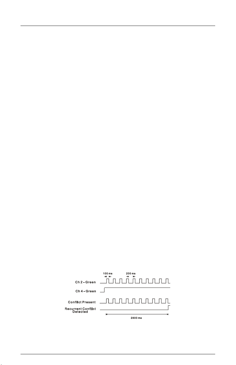
The figure below shows a simple example of a recurrent Conflict fault. Channel 2 Green is
detected active due to a malfunction of the load switch that caused the output to Aflicker@
On for 100 ms approximately every 200 ms. Because normal Conflict detection requires a
continuous fault of at least 350 ms duration, this event could go undetected. The Recurrent
Pulse detection algorithm will combine these pulses into one event and trigger a Conflict
fault once the longer recurrent timing threshold is exceeded.
When triggered by a recurrent fault condition, the Signal Monitor will enter the fault mode,
transfer the Output relay contacts to the Fault position, and illuminate the appropriate
CONFLICT, MULTIPLE, or LACK OF SIGNAL indicator. The unit will remain in the fault
mode until reset by the Reset button or the External Reset input. Fault response times will

CMU-24VDC-ITL Cabinet Monitor Unit
Operations Manual
Eberle Design Inc. Page 10
vary depending on the pulse width and frequency of the recurrent inputs, but will range
from 1000 ms minimum to 10.4 seconds maximum. Recurrent Pulse detection can be
disabled with the SEL1 option jumper, see Section 2.15.1.
2.15.1 RECURRENT PULSE DETECTION DISABLE
The Recurrent Pulse Detection function can be disabled by soldering a 0-ohm jumper into
position SEL1 on the CMU-24VDC printed circuit board. When the jumper is inserted,
Recurrent Pulse Detection is disabled. When the jumper is removed, Recurrent Pulse
Detection is enabled.

CMU-24VDC-ITL Cabinet Monitor Unit
Operations Manual
Eberle Design Inc. Page 11
Section 3
INPUT SIGNALS
3.1 FIELD SIGNAL INPUTS (LEDGUARD)
The Eberle Design CMU-24VDC uses a technique designed to better monitor the
characteristics of LED based signal loads called LEDguard. Each field signal input is
measured and compared to both a high threshold and a low threshold value to determine
On / Off status. This differs from conventional AC signal monitors where the active
threshold is picked according to the color of the signal. Once the high and low On / Off
thresholds have been determined using the input RMS voltage, the individual fault monitor
functions use the appropriate threshold to determine if a fault condition exists.
LEDguard
Green/Walk
Yellow
Red/Don’t Walk
Conflict
Low
Low
---
Red Fail
High
High
High
Dual Indication
Low
Low
Low
Clearance
Low
Low
High
All unused RED (DON’T WALK) field signal inputs must be terminated to the 24VDC
supply.
3.2 LED SIGNAL LOAD ELECTRICAL REQUIREMENTS
LED Signal loads shall meet the following requirements under all conditions of
temperature, time, etc:
1) the signal shall emit NO light when the terminal voltage is less than 6 Vrms, And
2) the signal shall emit light when the terminal voltage is greater than 16 Vrms, And
3) between the terminal voltages of 6 Vrms and 16 Vrms the signal may or may not emit
light.
3.3 LOAD SWITCH CURRENT
Load current is sensed by the AMU-24VDC based on total load current to all colors of a
channel. Total load current is an indication that a signal load is present. Lack of adequate
load current indicates no active load (i.e. burned out lamps) or an open field wire condition.
Load current monitoring is used by the Lack of Signal monitoring function (see 2.5) to
detect the loss of signal load while the load switch is in the On state.
- WARNING -
LED SIGNALS MUST MEET THE REQUIREMENTS OF SECTION 3.2
CARE MUST BE TAKEN AT EACH INSTALLATION TO ENSURE THAT THE
TOTAL VOLTAGE DROP DUE TO SIGNAL LOAD CURRENT IN BOTH THE FIELD
WIRE AND FIELD RETURN WIRE DOES NOT EXCEED 4 VOLTS TOTAL.

CMU-24VDC-ITL Cabinet Monitor Unit
Operations Manual
Eberle Design Inc. Page 12
A channel will be sensed active when the load current exceeds 105% of the Channel
Current Sense Threshold programmed for that channel in the Datakey. A channel will not
be sensed active when the load current is less than 95% of the Channel Current Sense
Threshold programmed for that channel in the Datakey. A load current value between 95%
and 105% of the Channel Current Sense Threshold may or may not be sensed active. This
provides a hysterisis value of +/- 5% of the Channel Current Sense Threshold.
The Channel Current Sense Threshold should be programmed for each monitored channel
based on the minimum signal load under all worst case conditions.
3.4 PDA CONTROL SIGNAL INPUTS
3.4.1 LOCAL FLASH STATUS
The cabinet should be wired such that operation of the cabinet in AUTO mode will place
24VDC on the LF STATUS pin. Operation of the cabinet in FLASH mode should be open
circuit on this input. This input will be considered active when the input voltage exceeds the
Active threshold defined in Cabinet Control 5.1. This input will not be considered active
when the input voltage is less than the Not Active threshold defined in Cabinet Control 5.1.
The CMU-24VDC will report the state of this input in the Type 189 frame. See section 2.9.
3.4.2 MAIN CONTACTOR (MC) COIL STATUS
The cabinet should be wired such that the MC COIL STATUS input is connected to the
24VDC side of the main contactor signal bus relay coil. An active signal on this input
indicates the Signal Bus should be powering the load switches. This input will be
considered active when the input voltage exceeds the Active threshold defined in Cabinet
Control 5.1. This input will not be considered active when the input voltage is less than the
Not Active threshold defined in Cabinet Control 5.1. The CMU-24VDC will report the state
of this input in the Type 189 frame.
3.4.3 MAIN CONTACTOR (MC) SECONDARY STATUS
The cabinet should be wired such that the MC SECONDARY STATUS input will be
connected to the output side of the main contactor signal bus relay. An active signal on this
input indicates the Signal Bus is powering the load switches. This input will be considered
active when the input voltage exceeds the Active threshold defined in Cabinet Control 5.1.
This input will not be considered active when the input voltage is less than the Not Active
threshold defined in Cabinet Control 5.1. The CMU-24VDC will report the state of this input
in the Type 189 frame.
3.4.4 FTR COIL DRIVE STATUS
The cabinet should be wired such that the FTR COIL DRIVE STATUS input is connected to
the FTR COIL DRIVE signal in the DC SIGNAL POWER BUS. An active signal on this input
indicates the flash transfer relays are energized and the field signals are driven from the
load switch outputs. This input will be considered active when the input voltage exceeds the
Active threshold defined in Cabinet Control 5.1. This input will not be considered active
when the input voltage is less than the Not Active threshold defined in Cabinet Control 5.1.
The CMU-24VDC will report the state of this input in the Type 189 frame.
3.4.5 CIRCUIT BREAKER (CB) TRIP STATUS
The cabinet should be wired such that the CB TRIP STATUS input will be connected to the
Auxiliary Switch output of the circuit breaker unit. The active state of this input indicates that
the circuit breaker unit is not in the tripped state. This input will be considered active when
the input voltage exceeds the Active threshold defined in Cabinet Control 5.1. This input will
not be considered active when the input voltage is less than the Not Active threshold
defined in Cabinet Control 5.1. The CMU-24VDC will report the state of this input in the
Type 189 frame.
CMU-24VDC-ITL Cabinet Monitor Unit
Operations Manual
Eberle Design Inc. Page 13
3.4.6 FRONT / REAR DOOR SWITCH
The cabinet should be wired such that +24VDC is applied to the DOOR SWITCH FRONT
or DOOR SWITCH REAR inputs when the respective door is Open. These inputs will be
considered active when the input voltage exceeds the Active threshold defined in Cabinet
Control 5.1. These inputs will not be considered active when the input voltage is less than
the Not Active threshold defined in Cabinet Control 5.1. The CMU-24VDC will report the
state of these inputs in the Type 189 frame.
The Datakey not present will cause a LFSA if the DOOR SWITCH FRONT input is sensed
as not active (door closed). See section 2.14.3.
3.5 MONITOR INTERLOCK
The MONITOR INTERLOCK input is connected to VDC GROUND within the CMU-24VDC.
The cabinet should be wired such that the lack of VDC GROUND on this pin forces the
cabinet to the flash mode. This prevents a cabinet from operating without a CMU-24VDC
installed.
3.6 EXTERNAL TEST RESET INPUT
The EXTERNAL TEST RESET input is used to reset the CMU-24VDC from the FSA
condition. When the EXTERNAL TEST RESET input is connected to VDC GROUND (True)
all front panel indicators will be illuminated for 100 msec and the OUTPUT relay energized.
Continuously activating the input will not affect CMU-24VDC operation.
The EXTERNAL TEST RESET input is intended for use in testing the CMU-24VDC and
should not be connected in the cabinet.
3.7 SERIAL BUS #1 ADDRESS INPUTS
The Address Select input pins ADDRESS 0 and ADDRESS 1 define the Serial Bus #1
address of the CMU. The pins are left open for a logical False, and are connected to VDC
GROUND for a logical True.
ADDRESS 1
ADDRESS 0
SB #1 ADDRESS
False
False
0x0F
False
True
0x10
True
False
0x11
True
True
0x12
The default address for the CMU is 0x0F. If multiple CMU units are not installed on Serial
Bus #1 these inputs should be left in the False (open) state.
3.8 SERIAL BUS #1 DISABLE INPUT
The SERIAL BUS #1 DISABLE input is used to prevent a Serial Bus #1 Error when
communications from the ATC is not active. When the SERIAL BUS #1 DISABLE input is
connected to VDC GROUND (True) The CMU-24VDC will not communicate on Serial Bus
#1 or set a FSA condition if communications from the ATC is not present. See section
2.3.1.
The SERIAL BUS #1 DISABLE input is intended for use in testing the CMU-24VDC and
should not be connected in the cabinet.
3.9 PDA TEMPERATURE
The CMU-24VDC will measure the ambient temperature in the PDA and report this value in
the Type 182 frame. This temperature indication may be used to analyze malfunctions that
could be related to over heating or cold conditions.

CMU-24VDC-ITL Cabinet Monitor Unit
Operations Manual
Eberle Design Inc. Page 14
Section 4
FRONT PANEL DESCRIPTION
4.1 INDICATORS
4.1.1 POWER INDICATOR
A green POWER indicator will illuminate to indicate 24VDC POWER voltage is proper. It
will flash at a 2 Hz rate when the 24VDC POWER input of the CMU or AMUs are less than
the DC Power Level Sense (see section 5.1).
It will remain Off when the 24VDC POWER voltage is less than 15 +/- 2 Vrms. See section
2.12.
4.1.2 24VDC FAIL INDICATOR
A red 24VDC FAIL indicator will illuminate when the CMU-24VDC is in FSA as a result of a
24VDC MONITOR cabinet power supply fault. See section 2.1.
4.1.3 12VDC FAIL INDICATOR
A red 12VDC FAIL indicator will illuminate when the CMU-24VDC is in FSA as a result of a
12VDC MONITOR cabinet power supply fault. The 12VDC FAIL indicator will pulse at a 2
Hz rate when the 12VDC monitor function is disabled. See section 2.1.
4.1.4 CONFLICT INDICATOR
A red CONFLICT indicator will illuminate when the CMU-24VDC is in FSA as a result of a
Conflicting Channels fault. See section 2.2.
4.1.5 LACK OF SIGNAL INDICATOR
A red LACK OF SIGNAL indicator will illuminate when the CMU-24VDC is in FSA as a
result of a Lack of Signal Inputs fault. See section 2.5.
4.1.6 MULTIPLE INDICATOR
A red MULTIPLE indicator will illuminate when the CMU-24VDC is in FSA as a result of a
Multiple Inputs fault. See section 2.6.
4.1.7 CU / LOCAL FLASH INDICATOR
A red CU / LOCAL FLASH indicator will illuminate when the CMU-24VDC is in FSA as a
result of a Type 62 command from the ATC (see section 2.4), the LOCAL FLASH STATUS
input is inactive (see section 2.9), or CB TRIP STATUS is inactive (see section 2.10).
4.1.8 CLEARANCE INDICATOR
A red CLEARANCE indicator will illuminate when the CMU-24VDC is in FSA as a result of
a Yellow Clearance or Yellow Plus Red Clearance fault. See section 2.7 and 2.8.
4.1.9 FIELD CHECK INDICATOR
A red FIELD CHECK indicator will illuminate when the CMU-24VDC is in FSA as a result of
a Field Check Mode fault. The indicator will flash at a 2Hz rate when the CMU-24VDC is in
FSA with Field Check Status as a result of Conflict, Lack of Signal, or Multiple fault. See
section 2.13.
4.1.10 SB #1 ERROR INDICATOR
A red SB #1 ERROR indicator will illuminate when the CMU-24VDC is in FSA as a result of
a Serial Bus #1 fault. See section 2.3.1. The SB #1 ERROR indicator will pulse at a 2 Hz
rate when the SERIAL BUS #1 DISABLE input is True. See section 3.8.

CMU-24VDC-ITL Cabinet Monitor Unit
Operations Manual
Eberle Design Inc. Page 15
4.1.11 SB #3 ERROR INDICATOR
A red SB #3 ERROR indicator will illuminate when the CMU-24VDC is in FSA as a result of
a Serial Bus #3 fault. See section 2.3.2.
4.1.12 DIAGNOSTIC INDICATOR
A red DIAGNOSTIC indicator will illuminate when the CMU-24VDC is in FSA as a result of
a Diagnostic fault. See section 2.14.
The DIAGNOSTIC indicator will flash at a 4 Hz rate if the Datakey is not present and a FSA
state does not exist. See section 2.14.3.
4.1.13 SB #1 RX INDICATOR
A yellow SB #1 RX indicator will pulse On each time the CMU-24VDC correctly receives a
frame on Serial Bus #1.
4.1.14 SB #3 RX INDICATOR
A yellow SB #3 RX indicator will pulse On each time the CMU-24VDC correctly receives a
frame on Serial Bus #3.
4.2 TERMINAL PORT
An EIA-232-E Data Terminal Equipment (DTE) interface is provided for interconnecting to a
personal computer using the EDI ECcom Signal Monitor Communications software
package. See the Eberle Design ECcom Operations Manual for further details. This port
is electrically isolated from the main CMU-24VDC power supply and 48VDC Ground.
A Null Modem cable is required for connection to a standard PC port.
4.3 RESET BUTTON
Depressing the RESET button resets the CMU-24VDC from the FSA condition after it has
been triggered by a fault. When the RESET button is depressed all front panel indicators
will be illuminated for 500 msec and the OUTPUT relay energized. Continuously
depressing the Reset button will not affect CMU-24VDC operation.
4.4 DATAKEY
The front panel mounted Keycepticletm is used to receive the Datakey serial memory
device. To install a Datakey, insert the key and rotate clockwise 90 degrees to the vertical
orientation. When a Datakey is installed while the power is applied to the CMU-24VDC, the
CMU-24VDC will load and verify the parameters and begin using the new configuration
immediately.
When a Datakey is removed while the power is applied to the CMU-24VDC, the CMU-
24VDC will continue to use the parameters from the removed Datakey until Reset is
applied, a new Datakey is installed, or a power-up cycle occurs.
If a CMU-24VDC is Reset or powered-up with the Front Door in the open position without a
Datakey installed or with an invalid Datakey, the CMU-24VDC will assume a default
Datakey configuration according to the Datakey Protocol Version.

CMU-24VDC-ITL Cabinet Monitor Unit
Operations Manual
Eberle Design Inc. Page 16
Section 5
SPECIFICATIONS
5.1 ELECTRICAL
Power Requirements
Operating Voltage ............................................................................................ 15 to 32 Vdc
Power Consumption (maximum)............................................................................. 10 Watts
Voltage Monitors
Field Signals High Threshold
Active...................................................................................... greater than 18.5 Vrms
Not Active ................................................................................... less than 17.5 Vrms
Field Signals Low Threshold
Active........................................................................................ greater than 4.0 Vrms
Not Active ..................................................................................... less than 3.0 Vrms
Cabinet Control (Local Flash Status, MC Coil Status, MC Secondary Status, FTR Coil
Drive, CB Trip Status, Front / Rear Door Switch)
Active...................................................................................... greater than 20.5 Vrms
Not Active ................................................................................... less than 19.5 Vrms
DC Power Fail Monitor
DC Power Level Sense Restore ......................................................... greater than 22 Vrms
DC Power Level Sense Dropout ........................................................... less than 21.5 Vrms
DC Voltage Monitors
+24 Volt Monitor
Active........................................................................................... greater than 22 Vdc
Not Active ......................................................................................... less than 18 Vdc
+12 Volt Monitor
Active........................................................................................... greater than 11 Vdc
Not Active .......................................................................................... less than 9 Vdc
Logic Inputs
External Test Reset, Serial Bus #1 Disable, Address 0, Address 1
Not Active (False) ........................................................................ greater than 16 Vdc
Active (True) ...................................................................................... less than 8 Vdc
CMU Temperature
Accuracy .....................................................................................................................± 6 oC
5.2 TIMING
Cabinet Power Supplies (+24VDC, +12VDC)
Fault ........................................................................................... greater than 500 ms
No Fault ........................................................................................... less than 200 ms
Typical ............................................................................................................ 350 ms
Conflict
Fault ........................................................................................... greater than 500 ms
No Fault ........................................................................................... less than 200 ms
Typical ............................................................................................................ 350 ms
Serial Bus #1 Error
Fault ......................................................................................... greater than 1000 ms
Serial Bus #3 Error
Fault ........................................................................................... greater than 300 ms
Table of contents


