Edic CR2 2700RC Owner's manual

CR2 COMPLETE
RESTROOM
RESTORATION
17 GALLON
PROFESSIONAL RESTROOM CLEANER
OWNER’S/OPERATOR’S MANUAL
PROUDLY DESIGNED AND MANUFACTURED BY
Revised 1-24-18

RECEIVING YOUR EQUIPMENT...................................................................................
WARNINGS AND SAFETY..............................................................................................
ELECTRICAL INFORMATION.......................................................................................
GFCI INFORMATION.......................................................................................................
GROUNDING INSTRUCTIONS......................................................................................
MAINTENANCE................................................................................................................
CORD STORAGE AND SAFETY....................................................................................
MACHINE LAYOUT..........................................................................................................
INCLUDED ACCESSORIES..............................................................................................
ASSEMBLING THE ACCESSORY RACKS....................................................................
OPENING THE MACHINE.............................................................................................
INSTALLING METERING TIPS......................................................................................
OPERATING INSTRUCTIONS FOR HARD SURFACE CLEANING.......................
RECOVERING LIQUID FROM HARD SURFACES.....................................................
USING THE BLOWER FEATURE...................................................................................
INSTALLING AN ACCESSORY HEATER (IF PURCHASED)...................................
USING AN ACCESSORY HEATER FOR CARPET OR UPH.....................................
CLEANING CARPET OR UPHOLSTERY WITHOUT A HEATER..........................
UPPER ASSEMBLY BREAKDOWN...............................................................................
LOWER ASSEMBLY BREAKDOWN.............................................................................
NOTES..................................................................................................................................
WARRANTY........................................................................................................................
3
3, 4
4
4,5
5
6
6
7
8
9
9
9
9,10
10
10
10,11
11
11
12,13,14
15,16,17
18
19
TABLE OF CONTENTS

UNPACKING YOUR NEW CR2:
When your package is delivered, check the carton care-
fully for signs of rough handling. If your CR2 is damaged,
notify the carrier immediately and request an inspection.
Be sure to keep the carton, packing inserts, packing lists
and carrier’s receipt until the inspector has veried your
claim.
EDIC’s liability ceases when the carrier picks up the ship-
ment. However, our customer service sta will be happy
to furnish any information needed in connection with
the claim and will attempt to expedite a resolution.
PLEASE READ BEFORE OPERATING YOUR
NEW CR2:
Read the manual carefully and completely before at-
tempting to operate the unit. is manual has important
information for the use and safe operation of the ma-
chine. Keep this manual handy at all times.
is equipment has been engineered and manufactured
to provide excellent performance and service. To ensure
that your equipment will continue to perform as intend-
ed:
• Maintain equipment regularly- following the suggest-
ed maintenance schedule provided.
• Use only original EDIC parts when servicing.
• Operate equipment with care.
If additional information is needed, please contact:
EDIC 800-338-3342
All information and specications printed in the man-
ual are current at the time of printing; however because
of EDIC’s policy of continual product development, we
reserve the right to make changes at any time without
notice.
FAILURE TO COMPLY WITH THE FOL-
LOWING WARNINGS AND INSTRUCTIONS
WILL VOID THE WARRANTY.
WARNING!
• e machine was designed for use on hard surfaces,
applications as per instructions and recommenda-
tions written in this manual. Any deviation from its
proper use or purpose and the consequential damage
that may occur is the sole responsibility of the end
user.
• Disconnect the power cord from the outlet before
servicing. Do not leave machine connected to an elec-
trical outlet when unattended.
• Do not immerse or use this machine in standing wa-
ter. Such use may cause electric shock.
• When using an extension cord, use only a 3-prong
conductor grounding cord-12 gauge wire or heavier.
• To avoid electric shock, do not expose the unit to rain
or snow. Store it indoors in a heated location only.
• Do not use the machine for dry vacuuming.
• Use defoamer at all times to prevent damage to the
vacuum motor.
• Do not use water in excess of 130°F (54°C) in the
solution tank
• To prevent seal damage and chemical build-up to the
pump system, run clean water through the solution
lines aer each day’s use.
• Use only commercially available carpet cleaning solu-
tions and defoamer intended for use with machines
of this type. Do not use dyes, bleaches, ammonia, or
other additives.
• e use of powdered cleaning solution, if not diluted
properly, may result in damage to the pump. Pow-
dered chemical is not recommended. If powdered
chemicals are used, premix in a separate container
before placing in the solution tank.
• Always read and understand your chemical’s MSDS
(Material Safety Data Sheet) before use.
• is equipment is not designed to handle or use
combustible/volatile substances such as gasoline or
kerosene, in, on, or near the machine. e use of such
materials will cause extreme hazardous condition.
• Do not expose machine to freezing temperatures.
3

• All repairs must be done by an authorized
EDIC repair station.
• Do not use replacement parts other than original
EDIC parts.
• Do not allow your spray stream to remain in one
xed location as surface damage may occur.
• Check that all spray nozzles are securely fastened.
Loose nozzles could be ejected from equipment at
high speeds.
• Prevent burns by wearing gloves or using a barrier to
remove hot quick disconnects.
• is is not a toy. Keep away from children.
• Do not pull by the power or use power cord as a han-
dle. Always unplug by grabbing the plug and pulling,
do not unplug by pulling the power cord.
• Inspect cord for damage. Do not use damaged cords.
Connect only to properly grounded outlets.
• Keep hair, ngers, loose clothing, and body parts
away from moving parts and openings.
• Turn o all controls before disconnecting machine
• Use caution with ejected liquid or chemicals. High
pressures and temperatures could be hazardous to
nearby people or surroundings.
• Do not tamper with, or disable GFCI function.
ELECTRICAL - 115 Volt
Model: CR2
is machine is designed to operate on a standard 15
amp, 120 volt, 60 Hz, AC circuit. Voltages below 105 volt
AC or above 125 volts AC could cause serious damage to
the motor.
WARNING: Do not tamper with or disable the
GFCI function.
GFCI FUNCTION:
For your safety, your CR2 is equipped with a built in
GFCI (Ground Fault Circuit Interrupter). e GFCI
function is automatic and, under normal operating con-
ditions, the GFCI function will not be activated.
A GFCI works by monitoring the amount of current that
is owing from hot to neutral. If the GFCI senses an im-
balance in that ow, such as a ground leak, it will disable
(interrupt) the electrical system to eliminate dangerous
operating conditions. When the electrical system has
been disabled, you will not be able to run the CR2, at all,
until you reset the GFCI.
Before resetting, It is best practice to investigate the cause
of a GFCI tripping the circuit.
Possible causes and solutions are:
• Your equipment has become wet and moisture has
come in contact with the electrical system. Take unit
to an authorized repair location for servicing.
• Your machine is submerged in liquid. If it is safe to
do so, remove the equipment and take unit to an
authorized repair location for servicing.
• ere is damage to the power cord. Replace the pow-
er cord immediately with the correct spec cord.
• e wall plug or cord plug may be wet or in contact
with water. Using thick rubber gloves, unplug the
cord from the wall.
• A leak in your machine’s plumbing may be wetting
the internal electrical components. Take the unit to
an authorized repair location for servicing.
• ere is a loose or faulty electrical connection some-
where in your equipment. Take the unit to an autho-
rized repair location for servicing.
To restore function to your equipment when the GFCI
has tripped the circuit, press the button on the GFCI
marked “RESET”.
If a GFCI continues to trip aer resetting, it indicates an
unsafe operating condition is present and it is best to take
it to an authorized repair location for servicing. Con-
tact EDIC for assistance in locating an authorized repair
location.
4
GROUNDING INSTRUCTIONS:
is piece of equipment must be grounded. Should an
electrical malfunction occur, grounding provides a path
of least resistance for electrical current- reducing the risk
of electric shock. is piece of equipment is furnished
with a cord that has a grounding conductor and ground-
ing plug. e grounded plug must only be plugged
into an appropriate outlet that is properly installed and
grounded in accordance with all local codes and ordi-
nances.
WARNING:
Connecting the equipment to an improperly grounded
outlet can result in an increased risk of electric shock. A
qualified electrician should be consulted if you are unsure
that the outlet is properly grounded. Do not modify the
plug provided with the equipment. If it will not fit the
outlet, have a proper outlet installed by a qualified electri-
cian.
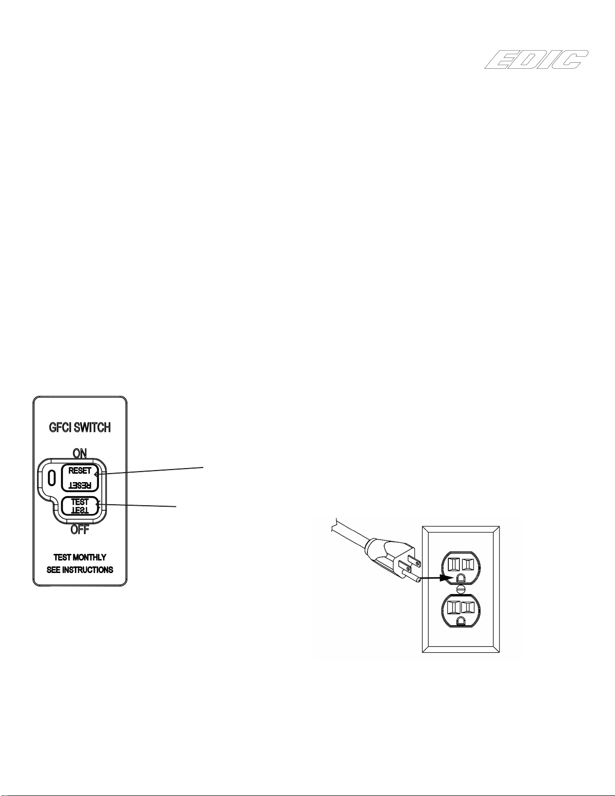
is appliance is designed for use on a 120-volt circuit.
e grounding plug provided looks like the plug illustrat-
ed in Figure 1. Replace the power cord if the grounding
pin is damaged or broken.
Extension cords connected to this machine should be
12 gauge, three-wire cords with three-prong plugs and
outlets. DO NOT use extension cords more than 25 feet
(7.6 m) long.
Figure 1
GFCI MAINTENANCE:
Although the GFCI function works on its own, it is nec-
essary to test for proper function of your GFCI periodi-
cally.
To do this:
1. Plug your equipment to an appropriate wall plug
2. Press the “TEST” button on the GFCI panel
3. Turn on the switches for “PUMP” and “MOTOR”
(located on the switch panel on the handle).
If your motors turn on, then the GFCI is NOT working
properly- do not use the equipment until this function
has been repaired. Take the machine to an authorized
repair location.
If neither motor powers on aer pressing the “TEST”
button then the GFCI is working properly.
Press the “RESET” button on the GFCI and the CR2 will
be fully functional again.
WARNING: Do not remove the grounding pin
from your power cord. Doing so will prevent
the GFCI from performing properly and can
allow dangerous operating conditions to go un-
detected. Replace power cords without ground-
ing pins immediately.
5
RESET
BUTTON
TEST
BUTTON

MAINTENANCE:
is CR2 has been engineered and built to require mini-
mum maintenance. But like any machine, it does require
some care to keep it in optimum working condition.
Careful attention to these maintenance instructions will
give you maximum operating performance and life ex-
pectancy of the machine.
CAUTION: Disconnect the power cord from the outlet
before doing any clean up or maintenance on the ma-
chine
1. Keep the machine clean. Do not allow dust to accu-
mulate on external surfaces or near any moving parts.
2. Aer every job, wipe down the surface of the ma-
chine with a clean damp cloth.
3. Inspect cord for damage. Do not use machine with a
damaged cord.
PERIODIC MAINTENANCE
• Use only chemicals safe for extractors
• Adhere to the appropriate mix ratios for all chemicals
• Do not add chemical to the solution tank- use the
chemical feed system or prespray
• For optimal performance, it is suggested that the
operator ush the system aer every job or at the end
of the day.
• Pump seals and valves may need to be replaced at the
1000 hour mark if a loss in pressure is noted
• e pressure regulator may require servicing should a
pressure drop be noted
Daily:
• Flush chemical lines with water by placing clean wa-
ter in the soulution tank and using the pump to spray.
• Check and clean vacuum lter
6
Weekly :
• Check and clean solution lter
• Check for obstructions in vacuum pathways
• Quarterly:
• Check pump, plumbing and ttings for leaks
• Check power cords and hoses for tears
CORD STORAGE:
While not in use, storage can be accomplished by wind-
ing cord around accessory racks. Cord should be
completely unwound during operation.
CORD SAFETY
• Do not leave appliance when plugged in. Unplug
from outlet when not in use and before servicing
• Do not use with damaged cord or plug. If appliance is
not working as it should, has been dropped, damaged,
le outdoors, or dropped into water, return to service
center for inspection and repair.
• Do not pull or carry by cord, use cord as handle, close
a door on cord, or pull cord around sharp edges or
corners. Do not run this CR2 over cord. Keep cord
away from heated surfaces.
• Do not unplug by pulling cord. To unplug, grasp the
plug, not the cord.
• Do not handle plug or appliance with wet hands.
• is equipment should be stored indoors and not
exposed to rain.
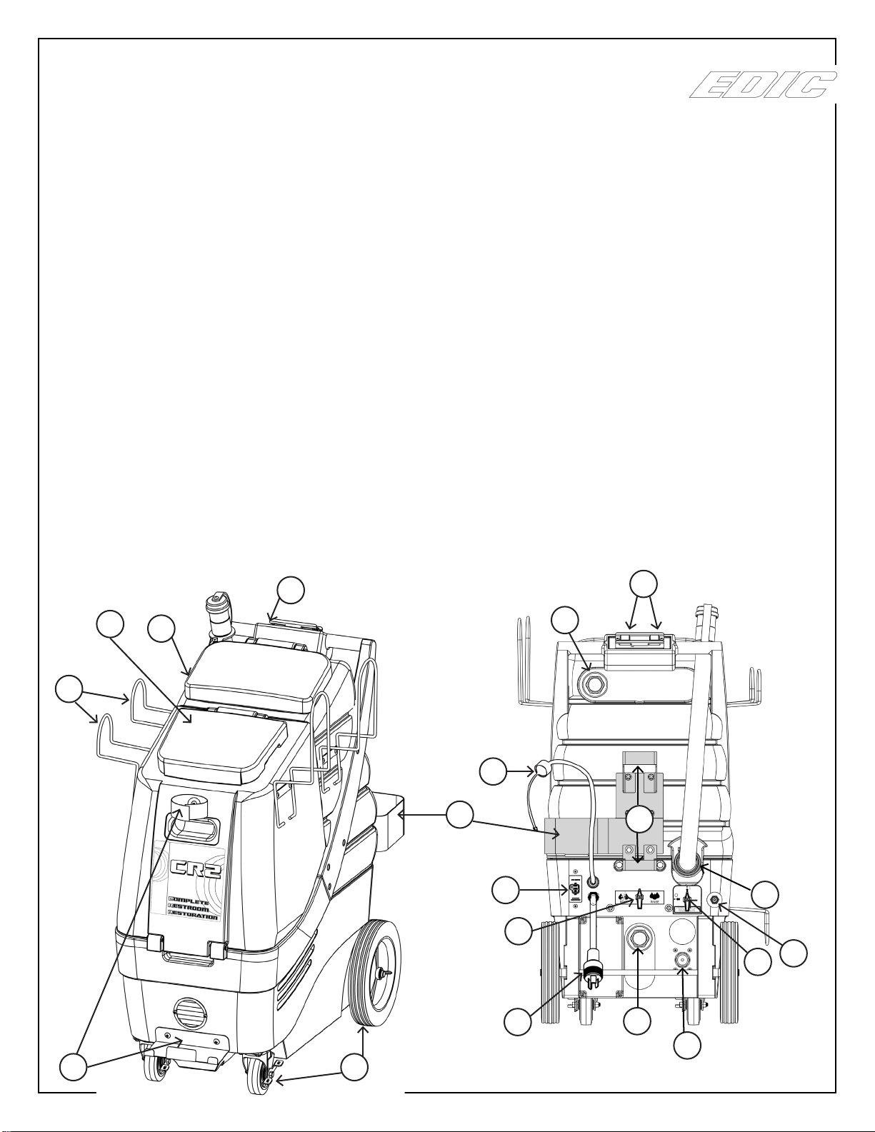
1. Handle- Used to maneuver and position the CR2
2. Recovery tank lid- Allows access to recovery tank
and creates a seal to ensure suction
3. Solution tank lid- Allows access to the solution tank
and prevents external contamination of solution tank
4. Accessory racks for hoses, cords, tools etc.- Two large
racks on one side and one three small racks on each
side of the machine. 5 total
5. Wand storage bracket and velcro strap- Allows the
operator to secure a wand attachment to the machine
for ease of transport
6. Non-marking front 4” locking casters and rear 10”
wheels
7. Recovery/vacuum hose inlet barb- connect your
recovery vacuum hose to this barb
8. Feed hose line for chemical with threaded bottle cap-
secures the feed hose line to the chemical bottle
9. Bottle holder for chemical feed system- Holds up to a
one gallon chemical bottle
10. GFCI breaker- Interrupts and disables the electrical
system if a ground leak is detected.
11. Chemical dispensing valve- Select between
“SOAP”and “RINSE” by turning to le or right as
marked
12. Power cord
13. Exhaust port hose barb- Used to connect to hose
with blower attachment.
14. Pressure regulator- Decrease pressure by turning
counter-clockwise or increase pressure by turning
clockwise
15. Priming/pressure relief valve- Prime system in the
event of air lock. Relieves pressure in the event of
pressure lock
16. Solution line Q.D.- Pressurized connection for solu-
tion line
17. Recovery tank dump hose
18. Heater mounting brackets- for accessory heater
19. Switch box- one switch marked “PUMP” and one
switch marked “VACUUM”. Switches light up when
powered on.
3 2
1
4
8
65
9
10
11
12 13
14
15 16
17
19
7
7
18

8
1. Part# 334ACH-2
2 piece wand and reversible brush/squeegee head
assembly. For scrubbing on one side and picking
up water on the other. Connects to hose #4 on this
page.
2. Part# K13686
“Gulper” tool Used to extract large volumes of water.
Connects to hose #4 on this page.
3. Part# 00604-50HPA
50FT high pressure solution line. Connects to quick
disconnect on CR2 (#16 on page 4)
4. Part #J14062A
45 FT Vacuum Hose. Connects to vacuum hose
inlet barb on CR2 (#7 on page 4)
5. Part #J14039A
45 Blow hose. Connects to Exhaust port on CR2
(#13 on page 4)
6. Part #9000AC-1
High Pressure gun. Connects to hose #3 on this
page.
7. Hand Squeegee
Used to remove excess liquid from smooth vertical
surfaces.
8. Part # J13975
Faucet Adapter. Presses on to most standard faucets
to easily ll the CR2 without using buckets.
*NOT SHOWN- ACCESSORY MESH BAG
1
2
3
4
5
6
7
8
8

9
Assembling the accessory racks:
e CR2 is shipped with the accessory racks and hard-
ware in the solution tank. When you receive your CR2,
it is necessary to secure the racks to the body. e only
tool required to complete the assembly is a Phillips head
screwdriver.
e CR2 comes equipped with pre-installed threaded
inserts in the body. e two larger racks and accessory
bag are installed on the le side of the machine (when
holding the handle). e three smaller racks are installed
on the right side (when holding the hanlde).
SOLUTION HOSE/POWER CORD RACK (3x)
D13698-3
10-32 x 1/2" TRUSS HEAD SCREW (10x)
VACUUM HOSE RACK (2x)
D13697-3
ACCESSORY RACK ASSEMBLY
ACCESSORY BAG
14591
ACCESSORY BAG
RETAINER D14577
ZF14568 REV 01 1/22/2018
Opening the machine:
is unit can be opened by simply removing two bolts
located on the back of the machine. e unit will open
forward by liing up on the handle. If you need to open
the unit further, you may release the vacuum hose going
from the base of the vacuum plate to the bottom of the
recovery tank by loosening the hose clamp at the base of
the recovery tank. 2 BOLTS
Installing metering tips for the Chemical feed
system:
Remove the semi-clear hose from the bottle cap (#8 on
page 7). Metering tips have a threaded pattern that is
matched to the bottle cap.
Select the appropriate metering tip, using the chart below,
and thread it clockwise into the threaded tube on the
bottle cap. Turn counter-clockwise to remove.
Metering tip color guide:
TIP COLOR RATIO OZ/GAL ML/L
TAN 128:1 1 7.8
PINK 64:1 2 15.6
LIGHT
BLUE
43:1 3 23.4
RED 32:1 4 31.2
GREEN 26:1 5 39.1
YELLOW 13:1 10 78.2
PURPLE 6.5:1 20 156.4
NO TIP 5:1 25 203

10
Hard surface Cleaning with Chemical feed
system:
e chemical feed system is designed to deliver accurate
chemical dilution for touchless surface cleaning.
1. Fill the solution tank of your CR2 with sucient wa-
ter for the task at hand.
2. Connect solution hose and accessory pressure gun.
3. Select the appropriate tip and install on the cap of the
chemical feed (#8 on page 7).
4. Place a bottle into bottle holder (#9 on page 7).
5. Take the feed tube attached to the cap (#8 on page 7)
and place it inside the bottle.
6. Take the cap from #8 on page 7 and thread it onto the
bottle of chemical to secure it in place.
7. Turn the chemical dispensing valve (#11 on page 7)
to the le toward the word “SOAP”.
8. Chemical will draw Accurately only in the “LOW”
pressure setting of your pressure gun. To activate the
“LOW” pressure, pop the collar of the gun out.
9. In “LOW” pressure, apply chemical to the walls and
xtures starting from the lowest point to the highest.
10. Spray the oor as you make your way out of the
room.
11. Allow the chemical to dwell according to the chemi-
cal manufacturers recommendations.
12. You may use the brush on your squeegee/brush wand
to agitate particularly soiled areas.
13. When you are ready to rinse away the chemical, sim-
ply turn the chemical dispensing valve (#11 on page
7) to the word “RINSE”.
14. Set your pressure gun to the desired pressure and
angle of spray by adjusting the collar. Rinse surfaces
starting from the top down.
15. See “Recovering liquid” for nal steps.
Recovering liquid from hard surfaces:
e CR2 is equipped with two dedicated tools for liquid
recovery: e squeegee/brush wand and the Gulper tool.
1. Connect recovery vacuum hose to the recovery inlet
barb (#7 on page 7).
2. Place the vacuum switch (see #18 on page 7) into the
“ON” position.
3. Using either the squeegee/brush wand or the Gulper
tool, to extract the liquid from the surface. (see page
8).
4. Monitor the levels in the recovery tank and empty
as necessary. Use defoamer to ensure your vacuum
motor does not take in foam/uid.
Using the blower feature:
To use, this feature connect the Blower hose (#5 on page
8) to #13 on page 7 and turn on the vacuum motor.
Convenient for:
• Blowing uid o countertops and walls onto the
oor
• Drying faucets and other xtures
• Blowing o dust
NOTE: Do not leave the blower hose on during nor-
mal extraction as it will restrict suction.
Installing an accessory heater:
If a 600HR Heat “n” Run heater system has been pur-
chased for the CR2, use the following illustration to
familiarize yourself with the heater.
1
2
4
5
3
6

1. Power switch- Lights up when switched to power
“ON”
2. “INLET” hose connect to male Q.D. (#16 on page 4)
3. Lamp will turn on anytime the heat element is
activated. Lamp will turn o any time max temp is
reached.
4. Male twist lock Pigtail- connects to 50 cord
5. “OUTLET” male Q.D.- Connect to your 35 solution
line
6. Handle
How to prepare an accessory heater for carpet
cleaning or upholstery:
1. Mount the Heater by lining up the two “legs” to the
two mounting brackets on the rear of the machine.
(#18 on page 7).
2. Connect your heater’s “INLET” hose (#2 on page 10)
to #16 on page 7.
3. Connect your 35 solution hose (#3 on page 8) to
the heater’s “OUTLET” Q.D. (#5 on page 10).
4. Connect your wand or upholstery tool to your 35
solution hose and 35 Vacuum hose.
5. Connect the power cord for the machine and the
power cord for the heater into two separate plugs on
two separate circuits. You may use a 988CS circuit
locater if available to locate two separate circuits.
6. Fill the solution tank of your CR2 with water.
7. Place the pump switch into the “ON” position.
8. Make sure Chemical Dispensing Valve is in the
“RINSE” position.
9. If necessary, allow pump to prime for 10-30 seconds
by turning the priming/pressure relief valve (#15 on
page 4) 45 degrees to the le to the “O” open posi-
tion.
10. Allow pump to prime
11. Close the priming valve.
12. Turn pump on and spray out of your wand or uphol-
stery tool until you have an uninterrupted stream.
13. Turn heater on and allow up to 3 minutes for the unit
to heat up.
14. e heater is ready for use once the green lamp (#3
on page 6) shuts o the rst time. Once you start
cleaning carpet, the green lamp will turn on and o
throughout your job as the thermostats regulate the
temperature.
15. Prespray as necessary.
16. Turn on the vacuum motor.
17. Spray on the backstroke and do a dry stroke when
pushing forward.
18. Overlap your previous path slightly when you pull
back.
19. Monitor the levels in the recovery tank and empty
as necessary. Use defoamer to ensure your vacuum
motor does not take in uid
DO NOT ALLOW HEATER TO BE RUN DRY.
DO NOT ALLOW HEATER TO FREEZE.
Cleaning carpet or upholstery without a
heater:
e CR2 can be used as a cold water extractor.
If you do not have an accessory heater, then perform the
steps below.
1. Prespray the area of carpet to be cleaned
2. Connect your solution line
3. Connect your recovery vacuum hose
4. Connect your wand or upholstery tool to the solu-
tion and vacuum hoses
5. Fill the solution tank of your CR2 with water
6. Make sure Chemical Dispensing Valve is in the
“RINSE” position
7. Place the pump switch into the “ON” position
8. If necessary, allow pump to prime for 10-30 seconds
by turning the priming/pressure relief valve (#15 on
page 4) 45 degrees to the le to the “O” open posi-
tion.
9. Allow pump to prime
10. Close the Priming valve
11. Turn on the vacuum motor
12. Spray on the backstroke and do a dry stroke when
pushing forward.
13. Overlap your previous path slightly when you pull
back
14. Monitor the levels in the recovery tank and empty
as necessary. Use defoamer to ensure your vacuum
motor does not take in uid
NOTE: e CR2 Chemical system does not apply chem-
ical in carpet mode. You may use traditional in-tank or
prespray methods.
11

12
45 1
57
53
8
34
15
41
9
33
40
46
55
51
52
28
25
16
35
48
6
2
26
24
5
56
54
30
22
4
7
32
47
59
11
18
60
19
12
23
36
49
43
24
2
12
27 20
30
12
42
21
29
20
27
37
58
38
14
17
10
39
50
44
31
13
2700RC
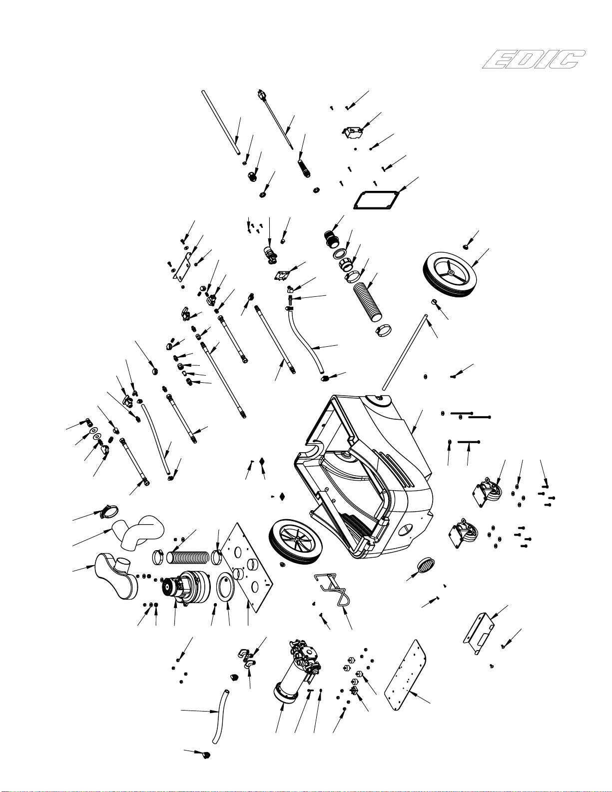
UPPER
1/24/2018
30
61
62

13
2700RC
UPPER
1/24/2018
ITEM NO.
PART NUMBER
DESCRIPTION
QTY.
1
10989-2A
BALL FLOAT 1
2
A00052
90 DEGREE ELBOW, .25" MP X .25" FP
4
3
A00060
BARB, .375" X .25" MPT, BRASS
1
4
A00124
LOCKNUT, .25NPT, BRASS
2
5
A00139
BARB, .25 X .25MP, BRASS
1
6
A13881
CHECK VALVE
1
7
A90004
BARB, .5 X .25MP, BRASS
1
8
B010314
WIRE HARNESS
1
9
B02211-1
ROCKER SWITCH
2
10
C00233
FLAT WASHER, USS, SAE, .25" ID
2
11
C00234
WASHER, FENDER, .25" ID, SS
1
12
C00238
1/4" ID SEALING WASHER
7
13
C00262
HEX NUT, 5/16-18, ZP
1
14
C00273
1/4-20 NYLON-INSERT LOCKNUT
2
15
C00295-1
#10 X 3/4" SHEET METAL SCREW, SS
2
16
C00313
1/4-20 X .75" HEX BOLT
4
17
C00313-1
HEX SCREW, 1/4-20 X 1/2, SS
2
18
C00316
SCREW, 1/4-20 X 3/4, PH, SS
1
19
C02251
JAM NUT, 1/4-20, SS
1
20
C02282
HEX BOLT, 1/4-20 X 1 1/2"
4
21
C02294
SCREW, 1/4-20 X 1 1/4, SS
6
22
C11144
SCREW, 1/4-20 X 2" SS
2
23
C11167
1/4-20 X 3/4" SCREW, SS
2
24
C11244
WASHER, 9/16" ID X 1.5" OD
3
25
C11540
WASHER, 5/16"
2
26
C12021
WASHER, FLAT, 9/16 ID, SS
1
27
C12039
FENDER WASHER, 1/4" ID, 1" OD
4
28
C12110
HEX BOLT, 3/8-16 X 1 3/4
2
29
C13361
SCREW, 1/4-20 X 1 1/2, TRUSS, SS
2
30
C14017
SCREW, 10-32 X 1/2", TRUSS
8
31
C14067
HEX SCREW, 5/16-18 X 1 1/4", SS
1
32
D00373
FILTER, INLET
2
33
D010284
SWITCHPLATE 1
34
D03421
COVER, SWITCHPLATE, 2 SWITCH
1
35
D13683
CHEMICAL BOTTLE HOLDER
1
36
D13697-3
HOSE RACK
2
37
D13698-3
RACK, SOLUTION HOSE/POWER CORD
2
38
D13711
HEATER BRACKET, UPPER
1
39
D13714
HEATER BRACKET, LOWER
1
40
E010453
GASKET, SWITCH BRACKET
1
41
E03433
GASKET, SWITCH BRACKET
1
42
E11128
DRAIN VALVE GASKET
2
43
E11836
GASKET, RECOVERY TANK, LID
1
44
E14058
SHRINK TUBING, 2.5" ID X 2.0" L
1
45
F11785-1
RECOVERY LID, GRANITE GREY
1
46
F11786-1
HANDLE, GRANITE BLUE
1
47
F11787-1-RC
SOLUTION TANK, GRANITE GREY
1
48
F11788-1
RECOVERY TANK, GRANITE GREY
1
49
F11791-1
SOLUTION LID, GRANITE GREY
1

14
2700RC
UPPER
1/24/2018
ITEM NO.
PART NUMBER
DESCRIPTION
QTY.
50
J00650
SCREW CLAMP #24 1.25 INCH
1
51
K00665-1
1.5" HOSE ADAPTER
2
52
K00666
1-1/2" 90 DEGREE ELBOW
1
53
K00672
PVC PIPE, 1.5" SCH40, 1.3125'
1
54
K00672-1
PVC PIPE, 1 1/2" X 2.25", SCH40
1
55
K00741
ADAPTER, MALE, 1 1/2", SCH40
1
56
K11185
90 DEGREE ELBOW, SCH40, MPT, SF
1
57
K11965
RETURN BEND, 1 1/2"
1
58
K13724
DRAIN HOSE ASSEMBLY
1
59
S11179
NON-SKID TAPE
1
60
S13706-A
STRAP, WAND, VELCRO
1
61
14591
ACCESSORY BAG
1
62
D14577
ACCESSORY BAG RETAINER BRACKET
1
15
2
17
58
20
78 80
4
13
42
12
65
14
9
11
8
10
15
71
21
23
32
34
6
50
69
18 81
39 72
29
27
26
83
28
55
67
45
66
84
16
40
70
38
60
51
5
49
7
3
75
41
30
77
63
35
59
61
33
82
57
48
25
68
43
44
64
19
79
22
36
47
24
1
31 73
76
62
30
32
30
34
39
77
74
37
52
32
2700RC
BASE
1/24/2018
46
53
73
70
13
4
56
54

16
2700RC
BASE
1/24/2018
ITEM NO.
PART NUMBER
DESCRIPTION
QTY.
1
--
HOSE ASSEMBLY
2
J00580
HIGH PRESSURE/TEMP HOSE .25" ID X 10" L
1
J00660
SWAGE FITTING, .25" FP
2
2
--
HOSE ASSEMBLY, .25" MP X .25" FP, 10" L
1
J00580
HIGH PRESSURE/TEMP HOSE .25" ID X 10" L
1
J00659
SWAGE FITTING, .25" MP
1
J00660
SWAGE FITTING, .25" FP
1
3
--
HOSE ASSEMBLY, .25" MP X .25" MP, 35" L
1
J00580
HIGH PRESSURE/TEMP HOSE .25" X 35"
1
J12932
CRIMP, .25" X .25" MPT, SWIVEL
2
4
A00052
90 DEGREE ELBOW, .25" MP X .25" FP
2
5
A00053
45 DEGREE ELBOW, .25" MP X .25" FP
1
6
A00055
NIPPLE, .125", CLOSE, BRASS
3
7
A00060
BARB, .375" X .25" MPT, BRASS
1
8
A00073
90 DEGREE ELBOW, BRASS
2
9
A00094C
BODY, CHECK VALVE, .25" M
1
10 A00094E
CHECK VALVE
1
11
A00097A
CAP, INLINE FILTER
1
12
A00104
QD, .25" M X .25" FP, BRASS
1
13
A00114B
HEX NIPPLE, .25" MP X .125" MP
4
14
A00134
90 DEGREE ELBOW, .25" BARB X .125" MPT
1
15
A00135
TEE, .125" FP X .125" FP X .125" MP
1
16
A00155
PLUG, MALE, .25"
1
17
A00161
TEE, .25" FP X .25" FP X .25" FP
1
18
A00168-18
BUSHING, .25" M X .125" F
1
19
A12917
ELBOW, .25" F X .375" M, NPT
2
20
A12960
NIPPLE, HEX, .25" X .25", BRASS
2
21
A12964
COUPLER, .25", BRASS
1
22
A13430
BARB, ELBOW, .375" MP X .5" BARB
1
23
A13688
BALL VALVE, 3-WAY, .125"
1
24
B00192
TIE HOLDER, W/ ADHESIVE
2
25
B02229
BRIDGE RECTIFIER, 25A
1
26
B11606
STRAIN RELIEF, PIGTAIL
1
27
B11821
STRAIN RELIEF
1
28
B11832
STRAIN RELIEF NUT
2
29
B13695
POWERCORD, 14GA, 50FT
1
30
C00233
FLAT WASHER, USS, SAE, .25" ID
18
31
C00261
HEX NUT, 1/4-20
3
32
C00273
1/4-20 NYLON-INSERT LOCKNUT
22
33
C00293
#8-32 X 0.5" PAN HEAD SCREW
2
34
C00313
1/4-20 X .75" HEX BOLT
3
35
C00314-1
HEX BOLT 1/4-20 X 1"
8
36
C02237
SCREW, #8 X .5" SMS, FH
2
37
C02242
SCREW, 1/4-20 X 1/2", TRUSS
2
38
C02305
CAP NUT, 1/2" PUSH-ON
2
39
C10737
#8-32 X .625" TRUSS HEAD SCREW, SS
6
40
C11165
SCREW, #8 X 1", PH, SMS
4
41
C11189
HEX BOLT, 1/4-20 X 4.5"
3
42
C11244
WASHER, 9/16" ID X 1.5" OD
2
43
C11955
WASHER, #10
1
44
C13026
SCREW, 10-32 X 1" HEX
1
45
C13120
#8-32 HEX NUT W/ LOCK WASHER
2
46
C14017
SCREW, 10-32 X 1/2", TRUSS
2
47
D11134-1
PLATE, VACUUM BASE
1
48
D11835
PLATE, PUMP
1
49
D13188
SHAFT, WHEEL, 18" X 0.625"
1
50
D13347
BRACKET
1
51
D13620
PLATE, REGULATOR
1
52
D13684
BRACKET, WAND
1

17
2700RC
BASE
1/24/2018
ITEM NO.
PART NUMBER
DESCRIPTION
QTY.
53
D13698-3
RACK, SOLUTION HOSE/POWER CORD
1
54
E00449
GROMMET
3
55
E11128
DRAIN VALVE GASKET
1
56
E11169
GASKET, VACUUM MOTOR
1
57
E13867
SANDWICH MOUNT, NEOPRENE
4
58
F11178-1
INTERCOOLER, SINGLE PORT
1
59
F11789-1-RC
CR2 BASE, GRANITE BLUE
1
60
F11790-1
HEATER PORT, COVER PLATE
1
61
F13820
LOUVER, 3", BLACK
1
62
G02517-1
MOTOR, VACUUM
1
63
G03518-L
CASTER, LOCKING, 4"
2
64
G11767
WHEEL, 10" X 1.75"
2
65
G13380
VALVE, PRESSURE RELIEF
1
66
G13634
REGULATOR, 300-500PSI
1
67
G13715
GFCI
1
68
G13869
PUMP
1
69
G14021
CHEMICAL INJECTOR
1
70
J00618
2" ID HOSE
2
71
J00632-1
PULSE HOSE, 32"
1
72
J00635
CLAMP, TUBE, .5" ID
1
73
J00639
2" ID HOSE CLAMP
4
74
J00651
HOSE CLAMP, .25" TO .625"
2
75
J11154
SOLUTION HOSE, 100PSI, WIRE, .375" ID X 5' L
1
76
J11154-1
SOL. HOSE .25" ID X 4.9'
1
77
J11508
SCREW CLAMP, #6
4
78
J11863 HOSE, INTERCOOLER
1
79
J11933
HOSE, POLYWIRE, PVC, .5" ID
1
80
J13152
CLAMP, HOSE, DOUBLE GRIP
1
81
J14016
TUBING, CLEAR, .25" ID, .5" OD, 5FT
1
82
K00662-50
SPACER, .5" X .5"
2
83
K00665-1
1.5" HOSE ADAPTER
1
84
K13843
ADAPTER, 1.5" PVC, SCH40
1

18
NOTES

19
LIMITED WARRANTY POLICY
To register your product warranty, visit our website at: www.edic-usa.com/warranty-registration/
LIFETIME on rotationally molded polyethylene tanks
2 YEARS on pump and vacuum motor and service labor involved
5 YEARS on service labor, and all other parts not covered by the Lifetime terms
EDIC REPLACEMENT PARTS LIMITED WARRANTY PLAN All parts sold as replacement parts for out-of-warranty EDIC prod-
ucts have the following Limited Warranty, with no warranty on labor: 30 DAYS
Your product is warranted to be free of defects in material and workmanship for the period set forth above, aer the date of delivery to
the retail purchaser, when operated in normal service and used in accordance with the operating and maintenance instructions in the
Owner’s Manual. is warranty is limited to and provides at no cost to the retail purchaser repair or replacement of parts determined to be
defective, at EDIC’s option, and labor, if provided for above, to replace or repair the parts (“service labor”) according to EDIC’s Standard
Rates, during the warranty period set forth above. is warranty excludes transportation charges unless authorized in writing by EDIC.
No warranty returns for refund or credit will be permitted. In the event of a defect, these are your exclusive remedies. Warranty claims
must be made in writing to EDIC prior to returning the product and no products will be accepted for repair or replacement without prior
authorization by EDIC. Use of parts not approved by EDIC in EDIC products will void this warranty. Warranty repair or replacement shall
not extend the original warranty period of the product, and replacement parts used for in-warranty repairs will only be warranted for the
remainder of the original warranty and not from their installation date. Any parts or product replaced under this Limited Warranty will
become the property of EDIC.
EXCEPTIONS AND EXCLUSIONS FROM THE WARRANTY. is Limited Warranty only covers product issues caused by defects
in material or workmanship during normal service. It does not cover product issues from any other cause, including but not limited to (a)
transportation damages; (b) alteration by unauthorized persons; (c) unauthorized use, unreasonable use, misuse, or abuse (including the
use of incompatible or corrosive chemicals or overloading of capacity); (d) failure caused by lack of proper maintenance and cleaning; (e)
normal wear on items such as cords, belts, hoses, switches, bumpers, gaskets, seals, carbon brushes, squeegees, harnesses, valves, cams, ex-
traction brushes, bearings, handle grips, lters and nishes; (f) acts of God; or (g) modication of or any part of the product. is Limited
Warranty does not cover EDIC products sold AS IS and WITH ALL FAULTS. is Limited Warranty is valid only in the United States and
Canada.
We suggest that you complete and return the enclosed product registration card promptly to facilitate verication of the date of the origi-
nal purchase. However, return of the product registration card does not eliminate the need for the retail purchaser to maintain the original
proof of the purchase in order to obtain the warranty benets. In the event that you do not have proof of purchase date, the purchase date
for purposes of this warranty will be the date of manufacture.
For specic information on how to obtain warranty services for your product, please write to: EDIC/Warranty Department 1753 Blake
Ave. Los Angeles, CA 90031
THERE ARE NO WARRANTIES WHICH EXTEND BEYOND THE DESCRIPTION ON THE FACE OF THIS STATEMENT. THERE IS
NO IMPLIED WARRANTY OF MERCHANTABILITY OR FITNESS FOR ANY USE ON THESE GOODS.
NO IMPLIED WARRANTY, INCLUDING ANY IMPLIED WARRANTY OF MERCHANTABILITY OR FITNESS FOR A PARTIC-
ULAR PURPOSE, APPLIES TO THE PRODUCT AFTER THE APPLICABLE PERIOD OF THE EXPRESS LIMITED WARRANTY
STATED ABOVE, AND NO OTHER EXPRESS WARRANTY, EXCEPT AS MENTIONED ABOVE, GIVEN BY ANY PERSON OR EN-
TITY WITH RESPECT TO THE PRODUCT SHALL BIND EDIC. EDIC SHALL NOT BE LIABLE FOR ANY FORM OF ACTION FOR
ANY DAMAGES, WHETHER DIRECT, SPECIAL, INCIDENTAL, CONSEQUENTIAL, OR INDIRECT, TO PROPERTY OR PERSON,
INCLUDING BUT NOT LIMITED TO, DAMAGE OR LOSS OF INCOME, LOSS OF PRODUCTION, OR LOSS OF PROFITS DUE TO
MALFUNCTIONING OF ANY PRODUCT, REGARDLESS OF THE LEGAL THEORY ON WHICH THE CLAIM IS BASED. IN NO
EVENT SHALL RECOVERY OF ANY KIND AGAINST EDIC BE GREATER IN AMOUNT THAN THE PURCHASE PRICE OF THE
PRODUCT SOLD BY EDIC, AND CAUSING
THE ALLEGED DAMAGE. WITHOUT LIMITING THE FOREGOING, YOU ASSUME ALL THE RISK AND LIABILITY FOR LOSS,
DAMAGE OR INJURY TO YOU AND YOUR PROPERTY AND TO OTHERS AND THEIR PROPERTY ARISING OUT OF USE OR
MISUSE OF, OR INABILITY TO USE, THE PRODUCT NOT CAUSED DIRECTLY BY NEGLIGENCE OF EDIC. THIS LIMITED
WARRANTY STATES YOUR EXCLUSIVE REMEDY.
Some states do not allow the exclusion or limitation of incidental or consequential damages, or allow limitations on how long an implied
warranty lasts, so the above limitations or exclusions may not apply to you. is Limited Warranty gives you specic legal rights and you
may have other rights which vary from state to state (or province).
Table of contents
Other Edic Ultrasonic Jewelry Cleaner manuals


